Transonic buff et control research with two types of shock control bump based on RAE2822 airfoil
2017-11-17YunTIANShiqiGAOPeiqingLIUJinjunWANG
Yun TIAN,Shiqi GAO,Peiqing LIU,Jinjun WANG
aNational Lab for Aeronautics and Astronautics,Beihang University,Beijing 100191,China
bSchool of Aeronautic Science and Engineering,Beihang University,Beijing 100191,China
Transonic buff et control research with two types of shock control bump based on RAE2822 airfoil
Yun TIANa,*,Shiqi GAOb,Peiqing LIUb,Jinjun WANGb
aNational Lab for Aeronautics and Astronautics,Beihang University,Beijing 100191,China
bSchool of Aeronautic Science and Engineering,Beihang University,Beijing 100191,China
Current research shows that the traditional shock control bump(SCB)can weaken the intensity of shock and better the transonic buffet performance.The author finds that when SCB is placed downstream of the shock,it can decrease the adverse pressure gradient.This may prevent the shock foot separation bubble to merge with the trailing edge separation and finally improve the buffet performance.Based on RAE2822 airfoil,two types of SCB are designed according to the two differentmechanisms.ByusingReynolds-averaged Navier-Stokes(RANS)andunsteady Reynolds-averaged Navier-Stokes(URANS)methods to analyze the properties of RAE2822 airfoil with and without SCB,the results show that the downstream SCB can better the buffet performance under a wide range offreestream Mach number and the steady aerodynamics characteristic is similar to that of RAE2822 airfoil.The traditional SCB can only weaken the intensity of the shock under the design condition.Under the off-design conditions,the SCB does not do much to or even worsen the buffet performance.Indeed,the use of backward bump can flatten the leeward side of the airfoil,and this is similar to the mechanism that supercritical airfoil can weaken the recompression of shock wave.
1.Introduction
In transonic flow conditions,the shock wave boundary layer interaction(SWBLI)and the flow separations on the upper wing surfaces of civil aircraft induce flow instabilities,‘buffet’,which may greatly affect its aerodynamic performance.Buffet tends to occur when the aircraft’s Mach number or angle of attack increases.Structure fatigue and flight accidents may be caused by the related ongoing oscillating loads in transonic flight.As a result,the flight envelope of aircraft can be significantly constrained.1
In terms of buffet control methods,the re are a huge amount of literatures on the control of the SWBLI.2–9The control methods can be divided into three main categories.The first category is aimed at energizing the boundary layer upstream of the shock,making it more resistant to the adversepressure gradient and consequently less likely to separate downstream of the shock.Mechanical vortex generator(VG),10–16,fluidic vortex generator(FVG)and synthe tic jet fall in this category.Previous studies done at ONERA17have shown that mechanical VG is able to delay the buffet onset at higher angles of attack.However,even though it has shown its efficiency for buffet onset delay,mechanical VG has the drawback of increasing drag under normal cruising conditions.This is the reason why FVG,which can be turned off,is also investigated.Moreover,mechanical VG can also be used in a closed-loop strategy to optimize the flow control and consequently to reduce auxiliary equipment for actuation,which is an important constraint for aircraft manufacturers.The second category is aimed at changing the trailing edge pressure of airfoil,and this can increase buffet onset lift coefficient.Trailing edge deflector(TED)and trailing-edgeflap fall in this category.18,19By increasing the camber,both TED and trailing-edgeflap decrease the buffet onset angle of attack,and this will be harmful while the airplane encounters gust.In addition,closed-loop TED needs complicated control law
design and actuation system.In the third category,the objective is to weaken the shock by splitting it to have a bifurcated λ shock structure.Several studies over the last decade have examined passive control devices to bring about the modified shock pattern:a cavity covered with a perforated plate20or a slotted cavity,21grooves and streamwise slots22,23underneath the shock foot.A promising method to lower the total pressure loss through the shock system is the shock control bump(SCB).In order to affect flow separation after shock wave,SCB must be in the proper position with proper size,which is difficult to achieve in complex flight conditions.5,24More recent studies were performed with 3D SCBs,which have a limited spanwise extent,to enhance the off-design performance.25–27

Table 1 Details of three different mesh sizes.
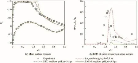
Fig.1 Comparison of different turbulence models.

Fig.2 Comparison of different mesh sizes.
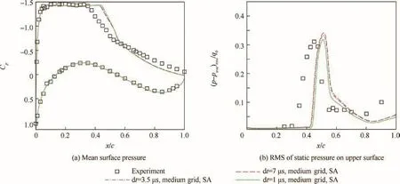
Fig.3 Comparison of different physical time steps.
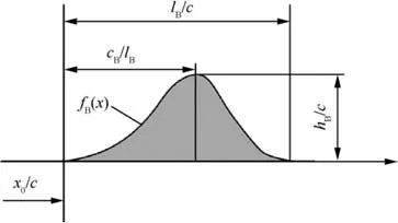
Fig.4 Definition of bump geometry and basic Hicks-Henne shape functions.

Fig.5 SCB shape comparison with RAE2822 airfoil.
In this study,we designed two different SCBs based on RAE2822 airfoil.Reynolds averaged Navier-Stokes(RANS)and unsteady Reynolds averaged Navier-Stokes(URANS)methods were used to investigate the performance of different airfoils.The results show that while the bump is mounted at a proper position,it can weaken the strength of the shock and eliminate the shock foot separation;while the bump is mounted slightly rearwards,it cannot weaken the shock wave but can decrease the adverse pressure gradient and delay the shock foot separation bubble merged with the rear separation.The mechanisms of two different bumps,based on controlling the intensity of shock and relieving adverse pressure gradient respectively,are furthe r explored.
2.CFD validation under buffet condition
The transonic buffet flow is so highly unsteady and nonlinear,making the corresponding study on flow stability difficult andcomplicated.28Some years ago,it was impossible to calculate such unsteady phenomenon and all buffeting studies were based on wind tunnel tests and flight tests.Nowadays,steady computations can predict the onset of the two-dimensional buffet with a low CPU cost,but the y are not able to determine the unsteady forces of the phenomenon and its mechanisms.At present,unsteady calculations of the buffet phenomenon on an airfoil can easily be performed with a model based on RANS equations with efficient numerical methods.29–32

Table 2 Parameters of two different SCB airfoils.

Fig.6 Mean and unsteady characteristics of different airfoils at Ma∞ =0.69,α=6°(where Cp*stands for critical pressure coefficient).

Fig.7 Mean and unsteady characteristics of different airfoils at Ma∞ =0.71,α =5.5°.

Fig.8 Mean and unsteady characteristics of different airfoils at Ma∞ =0.73,α =4.5°.

Fig.9 Mean and unsteady characteristics of different airfoils at Ma∞ =0.74,α =4°.

Fig.10 Mean and unsteady characteristics of different airfoils at Ma∞ =0.75,α=3.5°.

Fig.11 Mean and unsteady characteristics of different airfoils around Ma∞ =0.76,α =3°.
Flow conditions are the experimental ones in the ONERA S3Ch wind tunnel where investigations on the OAT15A airfoil were carried out.33OAT15A is a supercritical airfoil with a thickness-to-chord ratio of 12.3%,a chord length of 230 mm and a thick trailing edge of 0.5%of the chord length.Flow conditions were the following:the test upstream Mach number Ma∞=0.73,the stagnation conditionspst=6×10⁵Pa,Tst=300 K and Reynolds number based on the chord length Rec=3×10⁶.Transition was fixed near the leading edge at x/c=7%on both sides of the airfoil with a carborundum technique.The dimensions of the test chamber were 0.78 × 0.78 m2.Various angles of attack α were measured from 2.5°to 3.91°by a proper adjustment of the adaptive walls,the profile being fixed.

Fig.12 Iso-Mach contours and streamlines of different airfoils at Ma∞ =0.69,α =6°.

Fig.13 Iso-Mach contours and streamlines of different airfoils at Ma∞ =0.76,α =3.5°.
The convectivefluxes have been discretized using a third-order total variation diminishing(TVD)version of the Roe upwind scheme with Van Leer flux limiters applying the monotone upstream-centred schemes for conservation laws(MUSCL)extrapolation.Time integration has been performed implicitly by employing a second-order backward scheme in the context of the dual time-stepping approach.
In order to verify that different turbulence models and mesh convergence in space and time are capable of simulating the flow structure with separated areas over the upper surface,unsteady computations with different turbulence models have been performed at the angle of attack α =3.5°.First,three turbulence models have been assessed to model the buffet phenomenon.Thefirst turbulence model is the one transport equation Spalart-Allmaras(SA)turbulence model integrated up to walls with damping functions.The second one uses the two transport equations of the k-ω Menter model with a shear stress transport(SST)corrector.The last one is the explicit algebraic stress model(EASM)Gatski-Speziable in eddyviscosity.A medium C-H type mesh was selected(the detailed information is listed in Table 1)and the physical time step dt=3.5 μs was adopted(dt≈ 1 × 10⁻⁴c/U,where U stands for freestream velocity).
To compare with the experimental results,the averaged pressure coefficients Cpof different turbulence models are presented in Fig.1(a).It can be seen that the SA and SST models predict the shock location slightly downstream and the EASM was more seriously,but all of the turbulence models failed to predict the trailing edge pressure coefficient.From the root mean square(RMS)of the fluctuations of static pressure on the upper surface shown in Fig.1(b),it is observed that SA model shows the best agreement with the experimental data among all turbulence models,where p,paveand q0stand for static pressure,mean static pressure and freestream dynamic pressure.Hence,SA model is selected as the turbulence model in later investigation.
Secondly,the effect of mesh convergence in space was analyzed on three levels of mesh,and the details of the mesh are listed in Table 1.SA model was selected as the turbulence model and the physical time step of 3.5 μs was adopted.
The pressure distribution for the different types of gird coincides well with each other.What’s more,the medium grid and the fine grid are in good agreement with experimental results,which are plotted in Fig.2.However,the coarse grid fails to catch the peak of RMS of the statistical pressure fluctuations.
Thirdly,the effect of physical time steps was assessed.Fig.3 illustrates that the physical time steps have little effect on mean surface pressure and RMS of the statistical pressure fluctuations on the upper surface.Finally,we selected SA turbulence model,medium grid and dt=3.5 μs to the subsequent study.
3.SCB design based on RAE2822 airfoil
Main parameters of SCB34are determined as start point of the bump x0,bump length lB(for airfoil dimensionless chord length c=1),crest location cB/lBand bump heighthB.
Hicks-Henne shape functions were used to represent bump shape.The shape functions are defined as


Fig.14 Aerodynamic performance of different airfoils at Ma∞=0.69.

Fig.15 Aerodynamic performance of different airfoils at Ma∞=0.71.

Fig.16 Aerodynamic performance of different airfoils at Ma∞=0.73.

which is illustrated in Fig.4,where xBis the chordwise coordinate of the bump,andB
Based on the pressure distribution of RAE2822 airfoil at freestream Mach number from 0.69 to 0.76,we designed two types of SCB:one was placed forward and the other backward.The detailed parameters are shown in Table 2,and Fig.5 presents the profile of the se airfoils.
4.Buffet performance of RAE2822 airfoil and SCB airfoils
4.1.Performance of different airfoils under buffet conditions

Fig.17 Aerodynamic performance of different airfoils at Ma∞=0.75.

Fig.18 Pressure coefficient distribution of different airfoils at Ma∞=0.71.

Fig.19 Buffet boundary of different airfoils.
The mean pressure Cpdistributions,skin friction coefficient Cfand the RMS of static pressurefluctuations(p-pave)rms/q0(upper surface)of different airfoils,at Ma∞=0.69–0.76 around buffet onset angle,are illustrated in Figs.6–11.From the mean pressure distributions,it is obvious that the efficiency of shock reduction on the Forward SCB airfoil becomes weaker or detrimental as Ma∞increases.However,as the shock propagates rearwards with the increment of Ma∞,the Backward SCB airfoil starts to obviously weaken the intensity of the shock(at Ma∞=0.76).From Figs.6 –11,it can befound that the Forward SCB airfoil can eliminate the separation bubble at the foot of the shock at Ma∞=0.69 and Ma∞=0.71 but change nothing about the separation properties at Ma∞=0.73–0.76.On the contrary,the Backward SCB airfoil delays the separation bubbles at shock foot merged with the trailing edge separation at Ma∞=0.69–0.74 and eliminates the separation bubbles at Ma∞=0.75–0.76.Comparing the RMS of static pressure on the upper surface between different airfoils,we can see that the Forward SCB airfoil alleviates the fluctuations of pressure effectively near the shock at Ma∞=0.69–0.71,while it does not improve or even worsens the pressurefluctuation at Ma∞=0.73–0.76.Also,it is noted that the Backward SCB airfoil can decrease the fluctuations of pressure on the upper surface at different freestream Mach numbers.
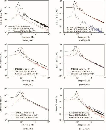
Fig.20 Lift coefficient PSD of different airfoils at different Mach numbers.
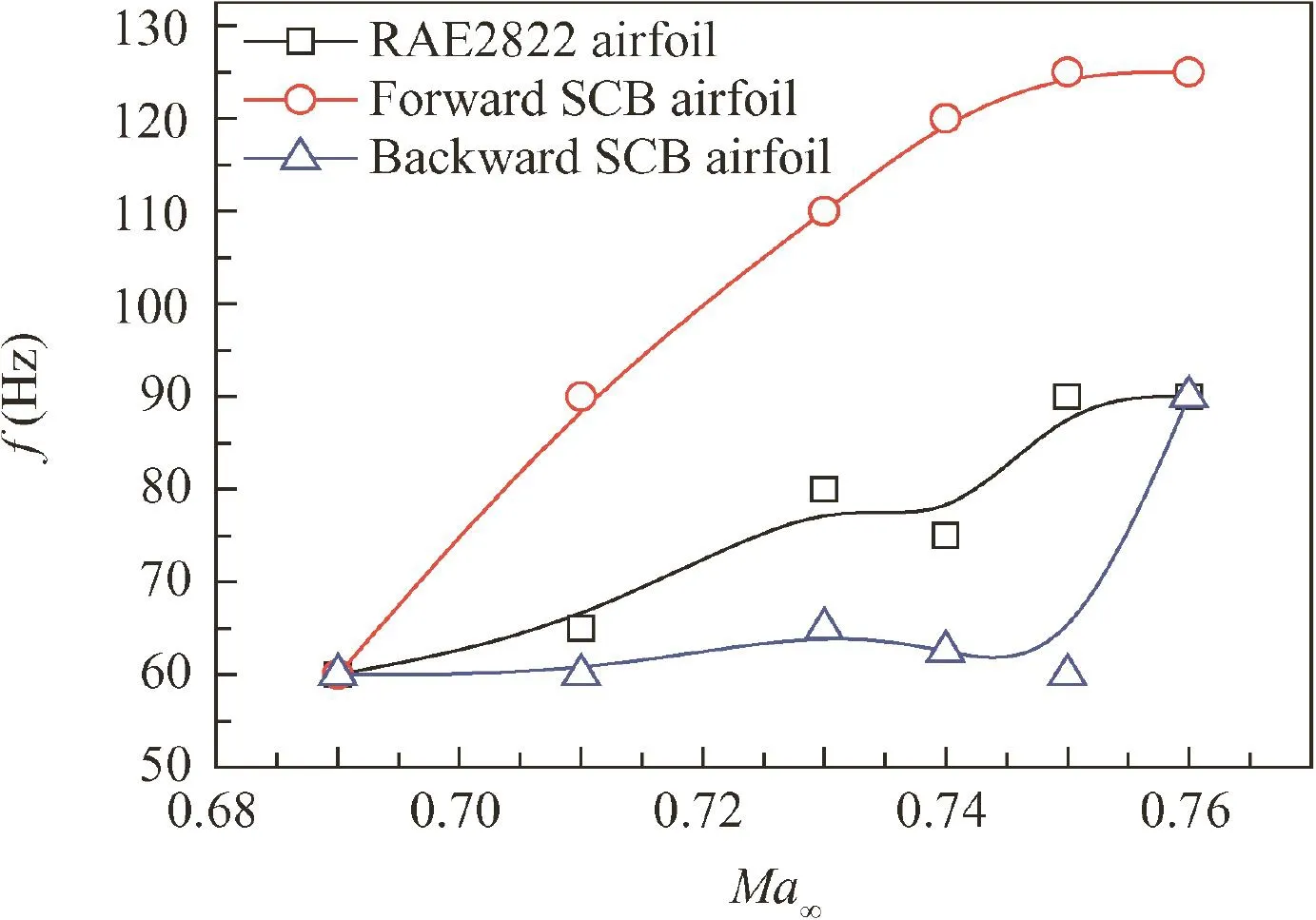
Fig.21 Basic frequency characteristic of different airfoils.
Fig.12 illustrates the mean Mach number contours and streamlines around different airfoils at the shock foot.It is obvious that the local Mach number reaches 1.43 ahead of the shock on RAE2822 airfoil,the re exists an obvious separation bubble at the shock foot,and the bubble has been merged with the rear separation which can be seen in Fig.6(b).The Forward SCB airfoil can reduce the shock-upstream Mach number from 1.41 to less than 1.27 according to isentropic compression,while the Backward SCB airfoil changes nothing to the shock strength,but it can suppress the separation bubble spreading rearwards.Fig.13 demonstrates that the rearward position of the shock(around 50%chord)induces a large separated flow on the basic airfoil because the adverse pressure gradient is behind the shock.Though the bump on the Forward SCB airfoil decreases the Mach number ahead of the shock on the upper surface,it provokes a lager rear separation because the bump augments the adverse pressure gradient behind the shock.The Backward SCB airfoil is less able to reduce the Mach number in front of the shock,but it can reduce the adverse pressure gradient behind the shock to eliminate the separation.
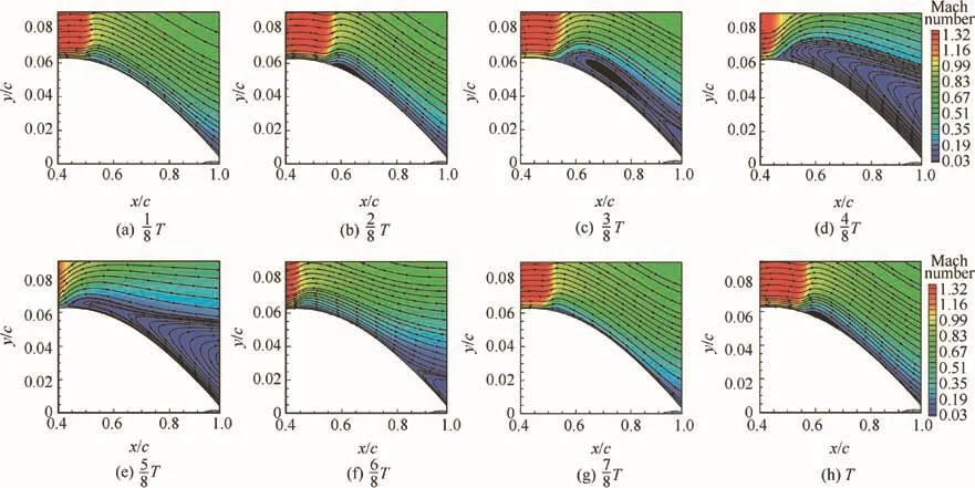
Fig.22 Mach contours and streamlines of RAE2822 airfoil in one buffet cycle(T)at Ma∞ =0.74,α=4.5°.
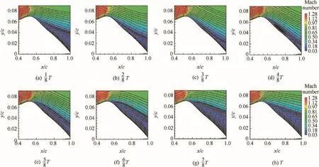
Fig.23 Mach contours and streamlines of Forward SCB airfoil in one buffet cycle(T)at Ma∞ =0.74,α =4.5°.
In summary,the Forward SCB airfoil can attenuate the pressure fluctuations,reduce the intensity of the shock and eliminate the separation bubble on the design point.But when the location of shock offsets the bump,the secondary shock will occur and the bump may augment the adverse pressure gradient behind the shock,which is mainly responsible for enlarging the separation bubble at shock foot merged with the trailing edge separation and amplifying the amplitude of the pressure fluctuations on the upper surface.When the shock lies relatively upwards,the Backward SCB airfoil,mounted slightly rearwards compared with the Forward SCB airfoil,can obviously weaken the adverse pressure gradient behind the shock and suppress the separation bubble at shock foot merged with the trailing edge separation.However,when the shock expands rearward,the Backward SCB airfoil will reduce the intensity of the shock and eliminate the separated bubble at the foot of the shock.In this situation,the role of Backward SCB airfoil has changed to that of Forward SCB airfoil.
4.2.General performance of different airfoils
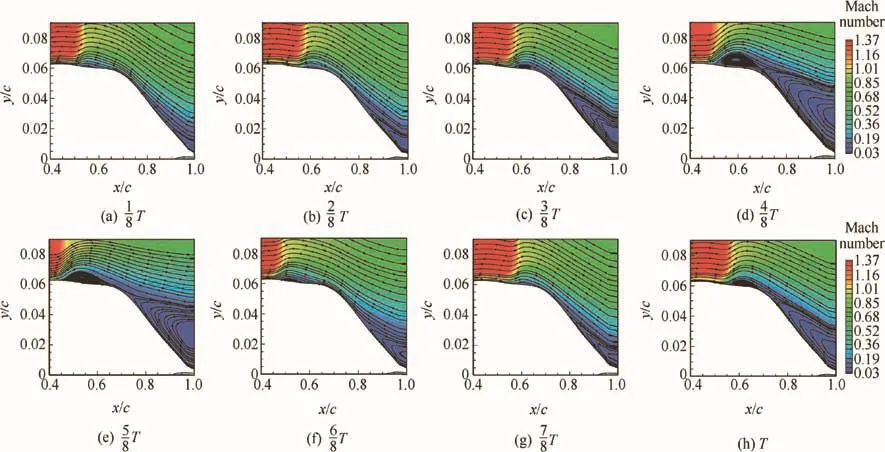
Fig.24 Mach contours and streamlines of Backward SCB airfoil in one buffet cycle(T)at Ma∞ =0.74,α =4.5°.
Based on RANS and URANS methods,further studies on the aerodynamic characteristics of different airfoils are performed by varying freestream Mach number and angle of attack.The results can be seen from Figs.14–17.Figs.14(a),15(a),16(a),17(a)illustrate that the tendency of lift coefficient for Backward SCB airfoil and RAE2822 airfoil is similar,while that for Forward SCB airfoil is totally different.It is obvious that the lift coefficient CLcurve of Forward SCB airfoil is much lower than that of the RAE2822 airfoil at low incidence.As the angle of attack increases,the lift coefficient experiences nonlinear increment and the maximum lift coefficient is slightly larger than others.Also it is noted that as freestream Mach number increases progressively,the stalling incidence of Forward SCB airfoil is gradually larger than that of Backward SCB airfoil and RAE2822 airfoil.
Figs.14(b),15(b),16(b),17(b)illustrate that the drag coefficient CDof Forward SCB airfoil is obviously higher than those obtained from Backward SCB airfoil and RAE2822 airfoil at low incidence,and the n becomes lower with the increasing angle of attack.This trend is more obvious with increase of the freestream Mach number.On the other hand,the drag coefficients of Backward SCB airfoil and RAE2822 airfoil are corresponding with each other at the same Mach number and incidence.Fig.14(c),15(c),16(c),17(c)indicate that the nose down pitch moment coefficient Cmzof Backward SCB airfoil is greater than that of RAE2822 airfoil and decreases by increasing the angle ofincidence,and for Forward SCB airfoil,the re exists a typical flat-plate before the stall angle.
In order to investigate the detailed property of the aerodynamic performance,the pressure distributions at Ma∞=0.71 and α =3°,4°,6°are picked up,which can be shown in Fig.18.There exist double shock waves produced by Forward SCB airfoil(Fig.18(a)),and notably the second one is so strong that it induces the trailing edge separation and weakens the leading edge suction,resulting in the decrement of lift coefficient and increment of drag coefficient.The Forward SCB airfoil,compared with the Backward SCB airfoiland RAE2822 airfoil,can moderate the shock wave which produces more lift and reduces the wave drag at α =4°and 6°,as shown in Fig.18(b)and(c).Instead,the variation ofincident has small effect on the Backward SCB airfoil.
The reverse move of shock wave position is determined as the criterion of buffet onset by using RANS method.Buffet boundary on different airfoils at Ma∞ranging from 0.69 to 0.76 is compared in Fig.19.It is obvious that the buffet onset angle and lift coefficient of the Forward SCB airfoil are higher at low subsonic Mach number,while the opposite is truefor a furthe r increasing Mach number.The Backward SCB airfoil can expand the buffet boundary at different Mach numbers.In conclusion,the Backward SCB airfoil has a wide range of buffet boundary arising from the weakness of adverse pressure gradient.
4.3.Buffet frequency characteristic of different airfoils
The lift coefficient power spectral density(PSD)of different airfoils at different freestream Mach numbers is compared in Fig.20.Different airfoils at the same Mach number perform different frequency and amplitude characteristics.The tendency of buffet amplitude is corresponding to the RMS of the static pressure on the upper surface.The main frequency f of lift coefficient PSD is determined as the criterion of buffet period.Fig.21 illustrates the basic frequency characteristics of different airfoils varying with Mach number.The increment level of Forward SCB airfoil is higher than that obtained from the basic airfoil.But the frequency of Backward SCB airfoil stays almost constant when Ma∞is lower than 0.75,and the n ascends dramatically to match the basic airfoil trends with furthe r increase of Mach number.
Taking the buffetpropertiesofdifferentairfoilsat Ma∞=0.74 as an example,the periodic flow behind the shock on the RAE2822 airfoil and the Backward SCB airfoil experiences intermittent separation and reattachment,while a fully separated flow occurs behind the shock on the Forward SCB airfoil shown in Figs.22–24.
It is uncertain that the mechanisms of buffet where the flow is essentially attached or partially separated.We take the buffet period,the time required for pressure wave traveling from the mean shock position to the trailing edge plus time required for disturbance traveling from the trailing edge to the mean shock position given by Lee35,36,Roos37,Crouch et al.38,as our criterion.Firstly,we set nine monitors on the upper surface of different airfoils at x/c=0.5,0.55,0.6,0.65,0.7,0.75,0.8,0.85,0.9 along the chord in order to detect the crosscorrelation of the unsteady pressure.The reference point is located at x/c=0.9 and R(x/c,0.9,t)is treated as the crosscorrelation coefficient along the chord varying with time at x/c=0.9.
From Fig.25(a),it can be seen that the pressure wave of RAE2822 airfoil moves quite slowly towards the trailing edge at x/c=0.7–0.9 but more rapidly at x/c=0.5–0.7.It can also be verified from Fig.16 that the separation flow appears all the time in the periodic cycle at x/c≈ 0.5–0.7 in contrast to the cyclicunsteady separation and reattachmentalternating between the range of x/c from 0.7 to 0.9.
Fig.25(b)illustrates that the pressure wave propagates rapidly rearwards at x/c=0.55–0.9 in contrast to the situation that it slows down where x/c ranges from 0.5 to 0.55.It can also be verified from the separated region behind the shock shown in Fig.17,which shows that the re is a steady separation at x/c=0.55–0.9 in the periodic cycle,and the position of the shock wave,where the re is also the maximum curvature of the SCB,is almost unchanged without obvious separation.
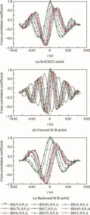
Fig.25 Cross-correlation functions of unsteady pressure at Ma∞ =0.74,α =4.5°.
From Fig.25(c),it can be seen that during the period of an oscillation cycle,the pressure wave propagates rearwards at x/c=0.7–0.9 along the chord and the n starts to moveforwards at x/c=0.6–0.7,and at x/c=0.55–0.6,it moves back towards the trailing edge and the n reverses upward at x/c=0.5–0.55.Fig.25 shows that the re is a steady rear separation at x/c=0.7–0.9 in the periodic cycle.The trailing edge separation is less able to move beyond the SCB due to the effect of surface curvature of the bump resulting in a relatively steady reattached flow.At x/c=0.55–0.6,the separation bubble is approaching to a steady state and the shock is oscillating at x/c=0.5–0.55.
The local mean Mach number Malocdistributions of three different airfoils are compared in Fig.26 at Ma∞=0.74,α =4.5°.The difference between the mean shock positions is distinguished.The shock position of the Forward SCB airfoil is at x/c=0.55 compared with that of RAE2822 airfoil lying at x/c=0.5.Combining with Fig.25(b),we can conclude that the timefor pressure wave traveling from the mean shock position to the trailing edge is shorter than that of RAE2822 airfoil.Concerning that the pressure wave spreads reversely against the shock wave on the surface of Backward SCB airfoil,it is difficult to predict the consuming time ofits downstream motion to the trailing edge.At least it is certain that the pressure wave traveling on the Backward SCB airfoil must take more time than that traveling on the RAE2822 airfoil.However,different airfoils share the same local Mach number ahead of the shock,which indicates that the sound wave on the surface of different airfoils spends time equally when it propagates from the trailing edge to the mean shock position.
In conclusion,the difference of buffet frequency between different airfoils is mainly because of the different time consumption from the shock position to the trailing edge.Comparing the flow field and the cross-correlation functions of unsteady pressure on upper surface,we can see that the re exists a fully separation behind the shock wave on the Forward SCB airfoil on upper surface and the speed of pressure wave is faster than that of other airfoils.However,the re exists a reattachment area between the shock foot separation bubble and trailing edge separation on Backward SCB airfoil,and the reattachment area retards the propagation of pressure wavefrom shock wave position to airfoil trailing edge.The unsteady flow on RAE2822 airfoil alternates between ‘shock foot separation bubble plus trailing edge separation” and ‘shock foot separation merged with trailing edge separation”periodically.In this case,the pressure wave speed of RAE2822 airfoil is between those of Forward SCB airfoil and Backward SCB airfoil.

Fig.26 Local mean Mach number distribution at Ma∞=0.74,α =4.5°.

Fig.27 Mach contours and streamlines of RAE2822 airfoil in one buffet cycle(T)at Ma∞ =0.69,α =6°.
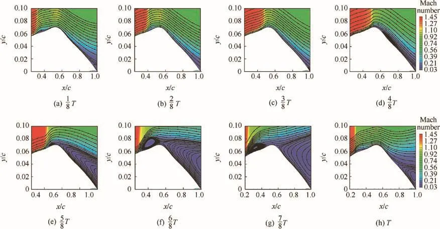
Fig.28 Mach contours and streamlines of Forward SCB airfoil in one buffet cycle(T)at Ma∞ =0.69,α =6.5°.
In order to validate the conclusion we proposed above,the periodic flow on different airfoils around Ma∞=0.69,α =6°,6.5° andMa∞=0.76, α =3°,3.5° isanalyzed.From Figs.27–29,we can see that the re exists a reattachment area between the shock foot separation bubble and trailing edge separation on all three airfoils in most of a buffet cycle.In this situation,all three airfoils fall into the same category as the Backward SCB airfoil at Ma∞=0.74,α=4.5°.And finally,the buffet frequencies of all three airfoils are almost the same and at a low value.
From Fig.30,we can see that the re exist ‘shock foot separation bubble plus trailing edge separation” and ‘shock foot separation merged with trailing edge separation”periodically,and this is similar to that of the RAE2822 airfoil at Ma∞=0.74,α =4.5°.Fig.31 illustrates that the re exists a full separation behind the shock on Forward SCB airfoil in most of a buffet cycle,and this is similar to that of the Forward SCB airfoil at Ma∞=0.74, α=4.5°.From Fig.32,we can see that the re exists a trailing edge separation that did not reach up to the shock wave position,and the attached flow between the shock foot separation and trailing edge separation retards the propagation of pressure wave.When the trailing edge separation has reached up to about x/c=0.7 in most of a buffet cycle,the buffet frequency increases dramatically compared with the case at Ma∞=0.74,α =4.5°,which can be verified from Fig.33.
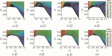
Fig.29 Mach contours and streamlines of Backward SCB airfoil in one buffet cycle(T)at Ma∞ =0.69,α =6.5°.
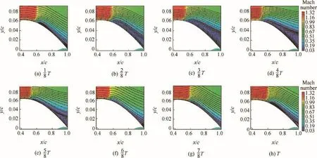
Fig.30 Mach contours and streamlines of RAE2822 airfoil in one buffet cycle(T)at Ma∞ =0.76,α =3.5°.
5.Conclusions
Current research shows that the SCB can diminish the intensity of shock wave and better the transonic buffet properties.The author found that SCB can also decrease downstream adverse pressure gradient to improve the characteristics of buffet.Based on the different mechanisms,two types of SCB con figurations installed on the RAE2822 airfoil were investigated.The first one,named Forward SCB airfoil,is mounted relatively forwards,which can reduce the intensity of shock wave at varying Mach numbers from 0.69 to 0.71 near the buffet onset conditions.The other one,named Backward SCB airfoil,is located rearward having an efficiency to alleviate the adverse pressure gradient behind the shock wave at different freestream Mach numbers.Then the URANS and RANS methods are utilized to carry out a close examination of the transonic buffet properties of different SCB airfoil configurations.
The results illustrate that the Forward SCB airfoil can improve the characteristics of buffet at varying Ma∞from 0.69 to 0.71,while it does little work to or even worsen the buffet performance where Ma∞ranges from 0.73 to 0.76.The Forward SCB airfoil can eliminate the separation bubble at shock foot as well as significantly reduce the shock intensity at the design point.However,under the off-design condition,the secondary shock wave occurs to further strengthe n the main shock or intensify the adverse pressure gradient.In contrast,the Backward SCB airfoil has better buffet performance in a wide range of freestream conditions,and the bump can weaken the downstream adverse pressure gradient as well as suppress the separation bubble at shock foot merged with the trailing edge separation.

Fig.31 Mach contours and streamlines of Forward SCB airfoil in one buffet cycle(T)at Ma∞ =0.76,α =3°.

Fig.32 Mach contours and streamlines of Backward SCB airfoil in one buffet cycle(T)at Ma∞ =0.76,α =3.5°.
Later on,the aerodynamic characteristics of different airfoils with varying freestream Mach number and angle of attack are furthe r explored by using RANS methods.The results obtained from comparing RAE2822 airfoil with two kinds of SCB airfoils show that the lift coefficient of Forward SCB airfoil drops at low incidence angle while the drag coefficient increases obviously.With the furthe r increase ofincidence angle,the lift coefficient of Forward SCB airfoil appears nonlinearly upwards and the re exists a slight increase of the maximum lift coefficient and stall angle.Apart from that,the properties of Backward SCB airfoil are similar with those of RAE2822 airfoil.
Finally,the buffet frequencies of different airfoils are investigated and the results show that the buffet frequency of Forward SCB airfoil,which is far above RAE2822 airfoil,ascends quite rapidly with the increase of Mach number.Instead,the frequency of Backward SCB airfoil remains relatively stationary and slightly less than that of RAE2822 airfoil.The speed of pressure wave traveling from the shock position towards the trailing edge is not the same for different airfoils,which makes the reason.Comparing the flow field and the cross-correlation functions of unsteady pressure on upper surface,we can see that when the re exists a full separation behind the shock wave,the speed of pressure wave is faster;when the re exists a reattachment area between the shock foot separation bubble and trailing edge separation,the reattachment area retards the propagation of pressure wavefrom shock wave position to airfoil trailing edge;when the re exist‘shock foot separation bubble plus trailing edge separation” and ‘shock foot separation merged with trailing edge separation”which alternate periodically,the pressure wave speed is between those of ‘shock foot separation bubble plus trailing edge separation”and ‘shock foot separation merged with trailing edge separation”;when the re exists a trailing edge separation that did not reach up to the shock wave position,the pressure wave speed is determined by the length of trailing edge separation and the length between shock wave position and trailing edge separation.

Fig.33 Cross-correlation functions of unsteady pressure on Backward SCB airfoil at Ma∞ =0.76,α =3.5°.
1.Zhang WW,Gao CQ,Ye ZY.Research advances of wing/airfoil transonic buffet.Acta Aeron Astron Sin 2015;36(4):1056–75,Chinese.
2.Thiede P,Krogmann P,Stanewsky E.Active and passive shock/boundary layer interaction control on supercritical airfoils Report No.:AGARD-CP-365.Paris:AGARD;1984.
3.Raghunathan S,Mabey DG.Passive shock-wave/boundary-layer control on a wall-mounted model.AIAA J 1987;25(2):275–8.
4.McCormick DC.Shock/boundary-layer interaction control with vortex generators and passive cavity.AIAA J 1993;31(1):91–6.
5.Birkemeyer J,Rosemann H,Stanewsky E.Shock control on a swept wing.Aerosp Sci Technol 2000;4(3):147–56.
6.Caruana D,Mignosi A,Correge M,Le Pourhiet A.Buffeting active control in transonic flowProceedings of the 21st applied aerodynamics conference.Reston:AIAA;2003.
7.Smith A,Babinsky H,Fulker JL,Ashill PR.Shock wave/boundary-layer interaction control using streamwise slots in transonic flows.J Aircraft 2004;41(3):540–6.
8.Molton P,Dandois J,Lepage A,Brunet V,Bur R.Control of buffet phenomenon on a transonic swept wing.AIAA J 2013;51(4):761–72.
9.Titchener N,Babinsky H.Shock wave/boundary-layer interaction control using a combination of vortex generators and bleed.AIAA J 2013;51(5):1221–33.
10.Lin JC,Selby GV,Howard FG.Exploratory study of vortexgenerating devices for turbulent flow separation controlProceedings of the 29th aerospace sciences meeting.Reston:AIAA;1991.
11.Mounts JS,Barber TJ.Numerical analysis of shock-induced separation alleviation using vortex generators Proceedings of the 30th aerospace sciences meeting and exhibit.Reston:AIAA;1992.
12.McCormick DC.Shock/boundary layer interaction control with vortex generators and passive cavity.AIAA J 1993;31(1):91–6.
13.Godard G,Stanislas M.Control of a decelerating boundary layer.Part 1:Optimization of passive vortex generators.Aerosp Sci Technol 2006;10(3):181–91.
14.Holden HA,Babinsky H.Effect of microvortex generators on separated normal shock/boundary layer interactions.Journal of Aircraft 2007;44(1):170–4.
15.Bur R,Coponet D,Carpels Y.Separation control by vortex generator devices in a transonic channel flow.Shock Waves 2009;19(6):521–30.
16.Rybalko M,Babinsky H,Loth E.Vortex generators for a normal shock/boundary layer interaction with a downstream diffuser.J Propul Power 2012;28(1):71–82.
17.Caruana D,Mignosi A,Robitaille C,Correge M.Separated flow and buffeting control.Flow Turbul Combust 2003;71(1):221–45.
18.Lee BHK.Effects of trailing-edgeflap on buffet characteristics of a supercritical airfoil.J Aircraft 1992;29(1):93–100.
19.Caruana D,Mignosi A,Corre`ge M,Le Pourhiet A.Buffeting active control in transonic flow Proceedings of the 21st applied aerodynamics conference.Reston:AIAA;2003.
20.Bur R,Corbel B,DÉlery J.Study of passive control in a transonic shock wave/boundary-layer interaction. AIAA J 1998;36(3):394–400.
21.Zhou W,Zhang ZK,Qu K.Numerical simulation of transonic airfoil buffet suppression with slotted cavity.Acta Aeron Astron Sin 2016;37(2):451–60[Chinese].
22.Smith AN,Babinsky H,Fulker JL,Ashill PR.Normal shock wave-turbulent boundary-layer interactions in the presence of streamwise slots and grooves.Aeron J 2002;106(1063):493–500.
23.Holden HA,Babinsky H.Separated shock-boundary-layer interaction controlusing streamwise slots.J Aircraft2005;42(1):166–71.
24.Wong WS,Qin N,Sellars N,Holden H,Babinsky H.A combined experimental and numerical study offlow structures over threedimensional shock control bumps.Aerosp Sci Technol 2008;12(6):436–47.
25.Ogawa H,Babinsky H,Pa¨tzold M,Lutz T.Shock-wave/boundary-layer interaction control using three-dimensional bumps for transonic wings.AIAA J 2008;46(6):1442–52.
26.Colliss SP,Babinsky H,Bruce PJK,Nu¨bler K,Lutz T.An experimental investigation of three-dimensional shock control bumps applied to transonic airfoils Proceedings of the 50th aerospace sciences meeting including the new horizons forum and aerospace exposition.Reston:AIAA;2012.
27.Eastwood JP,Jarrett JP.Toward designing with three-dimensional bumps for lift/drag improvement and buffet alleviation.AIAA J 2012;50(12):2882–98.
28.Quan J,Zhang W,Gao C.Characteristic analysis of lock-in for an elastically suspended airfoil in transonic buffet flow.Chinese J Aeronaut 2016;29(1):129–43.
29.Brunet V.Computational study of buffet phenomenon with unsteady RANS equationsProceedings of the 21st applied aerodynamics conference.Reston:AIAA;2003.
30.Xiao Q,Tsai HM.A numerical study of transonic buffet on a supercritical airfoil.AIAA J 2006;44(3):620–8.
31.Deck S.Numerical simulation of transonic buffet over a supercritical airfoil.AIAA J 2005;43(7):1556–66.
32.Garnier E,Deck S.Large-eddy simulation of transonic buffet over a supercritical airfoil.In:Deville M,LeˆTH,Sagaut P,editors.Turbulence and interactions.Proceedings of the TI 2009 conference.Berlin(Heidelberg):Springer;2010.p.135–41.
33.Brunet V,Deck S,Molton P,Thiery M.A complete experimental and numerical study of the buffet phenomenon over the OAT15A Airfoil40e`me Colloque AÉrodynamique AppliquÉe.Paris:ONERA;2005.p.1–9.
34.Sobieczky H.Parametric airfoils and wings.Notes Numer Fluid Mech 1998;68:71–88.
35.Lee BHK.Oscillatory shock motion caused by transonic shock boundary-layer interaction.AIAA J 1990;28(5):942–4.
36.Lee BHK.Self-sustained shock oscillations on airfoils at transonic speeds.Prog Aerosp Sci 2001;37(2):147–96.
37.Roos FW.Some features of the unsteady pressure field in transonic airfoil buffeting.J Aircraft 1980;17(11):781–8.
38.Crouch JD,Garbaruk A,Magidov D,Travin A.Origin of transonic buffet on aerofoils.J Fluid Mech 2009;628(1):357–69.
30 October 2016;revised 16 December 2016;accepted 24 January 2017 Available online 23 August 2017
Aerodynamics;
Buffet control;
RAE2822 airfoil;
Shock control bump;
Transonic
*Corresponding author.
E-mail address:aircraft@buaa.edu.cn(Y.TIAN).
Peer review under responsibility of Editorial Committee of CJA.
Production and hosting by Elsevier
http://dx.doi.org/10.1016/j.cja.2017.07.011
1000-9361©2017 Production and hosting by Elsevier Ltd.on behalf of Chinese Society of Aeronautics and Astronautics.This is an open access article under the CC BY-NC-ND license(http://creativecommons.org/licenses/by-nc-nd/4.0/).
©2017 Production and hosting by Elsevier Ltd.on behalf of Chinese Society of Aeronautics and Astronautics.This is an open access article under the CC BY-NC-ND license(http://creativecommons.org/licenses/by-nc-nd/4.0/).
杂志排行
CHINESE JOURNAL OF AERONAUTICS的其它文章
- Effect of an end plate on surface pressure distributions of two swept wings
- Determination of a suitable set of loss models for centrifugal compressor performance prediction
- Blade bowing eff ects on radial equilibrium ofinlet flow in axial compressor cascades
- A model offlow separation controlled by dielectric barrier discharge
- Research on parafoil stability using a rapid estimate model
- Tomography system for measurement of gas properties in combustion flow field
