Micro Structure of Injection Molding Machine Mold Clamping Mechanism: Design and Motion Simulation
2017-10-10ZhimingJinYajunZhangXinliangWangJacobWilliamsZhenLiuZhongyuanHuangLaurenFalknerGangZhouLiqunDongJianZhuangandZheWang
Zhiming Jin, Yajun Zhang, Xinliang Wang, Jacob Williams, Zhen Liu, Zhongyuan Huang, D’Lauren Falkner, Gang Zhou, Liqun Dong, Jian Zhuang, and Zhe Wang
MicroStructureofInjectionMoldingMachineMoldClampingMechanism:DesignandMotionSimulation
Zhiming Jin, Yajun Zhang, Xinliang Wang, Jacob Williams, Zhen Liu, Zhongyuan Huang, D’Lauren Falkner, Gang Zhou, Liqun Dong, Jian Zhuang*, and Zhe Wang*
With the advent of intelligence, more and more machines and devices involve the creation of complex structures. In the intelligent manufacturing industries, moldings including injection molding, blow molding, compression molding and others play critical roles in manufacturing the highly precise parts required for building intelligent machines (such as computers, cell phones, robots, etc.). The performance of the clamping mechanism directly affects the quality of the microstructure of injection products.The design of injection molding mold clamping mechanism is based on the microstructure characteristics of the trip of toggle lever mechanism ratio, speed ratio, and force amplification ratio. These are used to study the main performance parameters, such as analysis, as well as for the establishment of the physical model of the clamping mechanism. The model is based on the microstructure of injection of hyperbolic elbow clamping mechanism kinematics simulation.Simulation results and the theoretical calculation contrast analysis shows that the maximum dynamic template speed is 215.34 mm/s.The dynamic templates and crosshead speed ratio is 2.15, therefore the design of injection molding mold clamping mechanism for microstructure provides favorable technical support. The method described here is important to build complicated molds required to build highly precise parts to build intelligent machineries.
microstructure injection molding; mold clamping mechanism;dynamics simulation;intelligent molding; intelligent devices
1 Introduction
In recent years, microstructure injection molding machines have been applied in optics, microfluidic devices, tiny medical instruments, MEMS, etc.[1-4]. Micro injection molding products are usually with the scale of mg unit, micron level of size, and its processing surface microstructure is micron grade. Compared with the traditional injection molding machine, the microstructure measuring injection volume and injection molding machines must operate more accurately, therefore more accurate clamping performance is required[5-7]. The microstructure of injection molding machine clamping mechanism mainly adopts that of hyperbolic elbow clamping mechanisms. Although hyperbolic elbow structure has large clamping force, stress, high efficiency, etc., it has articulated easy wear, the clamping force is not stable, the impact process is big, and the overall size is larger[8, 9].Such intelligent system analysis and novel molds development can afford to offer advantages in new clap design, new injection design, new advanced control, integrated robotics and precise process control.
In order to tackle the hyperbolic maximum elbow clamping mechanism defect, researchers conducted extensive research. Gao[10], of the five point double toggle clamping mechanism motion characteristics and force analysis, established a mathematical model with the target function theory, the maximum force amplifying ratio and minimum overall axial size, and the parameters for design and motion simulation. Study and analysis on the Zhang[11]of the toggle mechanism and influence of speed bit faster than the relevant parameters, a comprehensive analysis of the international market on the part of toggle clamping mechanism than the speed of the data, puts forward the design optimization of toggle mechanism of speed ratio curve and performance measures and methods. Under the condition of ignoring inertia force, Lin and Kuo etc.[12]proposed a method to estimate the crosshead response to thrust formula of clamping force. Zhong[13]built the toggle mechanism model, carried out the movement simulation, and verified the reliability and feasibility of the toggle mechanism, all of which will be designed and applied to the actual development to meet the performance requirements. Shao[14]has incorporated hybrid drive theory into the clamping mechanism design, design a servo motor and the conventional motor for hybrid drive mode locking mechanism, which enabled the kinematics simulation and optimization design. Existing research efforts have improved the performance of the locking mechanism to a certain extent, however, the rationality of the structure and stability of the locking mechanism still needs further optimization and improvement.
Based upon several aforementioned representative ingenious systems, the ultimate goal is to introduce effective techniques for the fabrication of microstructures with high precision at efficient cost. This mission also relies on the sophisticated computational approaches for mechanisms design under rationalizing the process of mechanical system. Such rationalization in complex mechanical motions can be synthesized by various building blocks. In addition, new materials, such as carbon materials[15], polymer[16-18], nanomaterials and nanocomposites[19-23], play more and more important role in our lives, so it is significant to develop injection molding machines with better performance and could be applied in new materials. In order to realize the intelligent machining and processing, the fundamental understanding of laws of mechanics/physics take on greater significance in the molds development process. Key mechanical components such as toggle level, toggle mold mechanism, locking and clamping, etc., can indeed affect system reliability and promote higher processing performance. Novel molds manufacturing can offer advantages to next generation machining process, with much higher reliability, performance and sustainable operation.
In this paper, the performance analysis of mold clamping mechanism of injection molding machine based on the microstructure, stress, travel focus on double toggle clamping mechanism, speed ratio, and ratio of force amplifying ratio of main performance parameters are calculated and analyzed. Moreover, microstructure injection molding machine clamping mechanism schematic design and theoretical analysis are presented.
2 Design and Theoretical Analysis of Clamping Mechanism for Micro-Structure Injection Molding Machine
2.1Togglelevermechanismdesignandcalculation
The performance of the locking mechanism will be directly related to the quality of the product. In order for the design of a qualified mold clamping mechanism to meet the requirement of specific[15], the clamping mechanism needs a clamping force to act on an accurate and precise template location. The main performance index of 500 kN locking mechanism of the clamping force, mold closing stroke 250 mm, maximum modulus and thickness of 250 mm.
Fig.1 shows a five hinged double toggle mechanism diagram, where the dotted line represents the toggle mechanism clamping starting position, and the solid line shows the clamping position.

Fig.1 Toggle lever mechanism.
According to the toggle mechanism schematic drawing point configuration diagram of the elbow bar mechanism in Fig.1, the solid line and dotted line graphs of the corresponding bars create equal constraint, the dotted line clamping position of rodL1andL2adds collinear constraint, rodL6has a vertical constraint, and rodL2and the dynamic template connecting terminal have a horizontal line applying collinear constraint. The microstructure of injection molding machine design requires a clamping force of 500 kN, a mold closing stroke of 250 mm, a maximum modulus and thickness of 250 mm, as well as the design parameters of the elbow bar mechanism shown in Table 1.
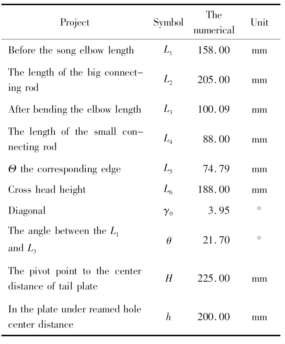
Table 1 Toggle lever mechanism geometry size.
2.2 The analysis of toggle mold mechanism
As shown in Fig.1, the solid line represents the toggle mold mechanism in place of the bars and movable plate location. At the time the toggle rodL1and DalianL2are collinear, the dynamic template reaches the limit position. The dotted line is the position of toggle mechanism at any one time.S0is the cross head displacement, andSTis the displacement of the movable template. According to the length and positon of the geometry, the relationship between the cross head travel and move mold board stroke is:
S0=L3[cos(θ+γ0)-cos(α+θ+γ0)]-
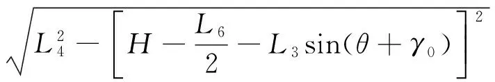
(1)
The move mold board stroke and cross head travel ratio is:
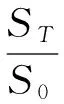
(2)
To move the template displacementSTis equal to the move mold board strokeSmax=250 mm, uses MATLAB software to the parameters into the equation, the mold in place when the crank angle maximumαmax=104.74 degrees, mold in place when the crankshaft angleαis 0. Cross head travelS0216.38mm, travel value is about 1.15 longer than the maximum, meet the stroke than experience value range (1.05~1.25).
In order to move, the template displacement,STmust be equal to the mold board stroke,Smax=250 mm. MATLAB software was used to substitute the parameters into the equation. When the mold is in its first position, the maximum crank angle,αmax=104.74 degrees. When the mold is in its second position, the crankshaft angle is 0 degrees. Cross head travelS0216.38 mm, travel value is about 1.15 longer than the maximum, meet the stroke than experience value range (1.05~1.25).
2.3Togglelevermechanismspeedthantheanalysisandcalculation
Fig.2 shows a toggle mechanism motion to arbitrary position diagram.V0is the cross head speed, andVmis the moving platen speed. According to the instantaneous center method, the instantaneous center of the velocity of the small connecting rod forL4isF, and the former toggleL1instantaneous center of velocity isA. Dalian rodL2instantaneous center of velocity for theGspot, by the instantaneous center method and geometric relations, is as follows:

(3)

(4)

(5)

(6)
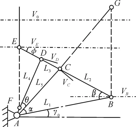
Fig.2Togglelevermechanismvelocityanalysisdiagram.
Theβangle and angle by the triangular relationship:
(7)

(8)
The parameters into the above formula was: in the mold begins, faster thanMvfor the maximum, about 4.49, in the mold closing end faster thanMv0. So in the mold closing process, dynamic template motion law accords with slow-Fast-slow requirements.
Substituting the parameters into the above formula results in faster thanMvfor the maximum (about 4.49) as the mold begins, and faster thanMv(0) at the mold closing end. Therefore, in the mold closing process, dynamic template motion law accords with slow-fast-slow requirements.
2.4Theamplificationratioanalysisofelbowbarmechanismofforcecalculation
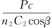
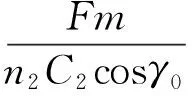
As shown in Fig.3,F0is the cross head screw thrust, andFcis the system deformation force, and is equal to the cross head thrust through the toggle mechanism amplified clamping force,Fm. The toggle mechanism sketch map is split into three parts. Fig.3 (a) is a cross head force decomposition map, Fig.3 (b) is the dynamic template force decomposition map, and Fig.3 (c) is the curved toggle force decomposition map, based on the static equilibrium relationship and geometric relations shown below.
F0=2F4×cosφ
(9)
L1sin(α+γ0+β)=L3sin(α+θ+γ0+φ)
(10)
F4×h4=F2×h2
(11)
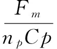
Fm=Fc=2F2×cosβ
(12)
By the above formula:

(13)

Fig.3 Toggle force diagram.
After substituting the parameters into the above formula, it is clear that the force amplifying ratio increases with decreasing crankshaft angle. When the crankshaft angleαis 3 DEG, the amplification ratio of force is 20.37. When the mold is in place, the crank angle α is 0 degrees, the force amplifying ratio is infinity, rodsL1andL2are collinear, and the toggle mechanism is in a self-locking state. So in the mold closing fast in place, the cross head only needs a small force to complete the mold closing action, and in the opening at the beginning, the cross head also only needs a small force to complete the opening action.
2.5Theanalysissystemofdeformationforcecalculation
In the process of mold closing in, gradually driving in the toggle mechanism template close to the front plate, when parting from the surface mold template and moving on to the front panel of the junction, the elbow angleαvalue reaches the critical angleαvalue of 0.As shown in Fig.4, the pull rodLpis elongated by ΔLp, ΔLktoggle is compressed, the clamping mechanism is elongated overall by ΔL, and the front plate and tail plate deflection aref1fq, respectively. The first computing to design combined deformation mode force when rod. And then determine the clamping mechanism is started when the deformation position, namely elbow angleαvalue reaches the critical angleα0the main parameter values. Finally get the formula for calculating the deformation force.

Fig.4Schematicdiagramofmouldclampingmechanismofdeformation.
By the tensile elastic deformation formula:

(14)

(15)
(16)
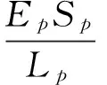
This leads to parameters ofFm=500 kN,Np=1 548.64 mm,Sp=2 463.01 mm2,Ep=2.1×10⁵N/mm2,Np=4 and ΔLp=0.38 mm.
2.6Calculationofthecriticalangleα=0system
The critical angleα0is a very important parameter of the toggle mechanism. The size of the clamping force is proportional to the size of the critical angle, and the clamping force size will affect the quality of products. Clamping force is small and the critical angle produces a smallerclamping force, so that the mold cannot lock due to overflow material, or the product causes flash. At smaller critical angles, the mechanism is unable to lock, affecting the performance of the mold clamping mechanism.
Through the deformation system in providing 500 kN clamping force under the circumstances to calculate bending the elbow angleαreaches a critical angleα0when the rod position. As shown in Fig.4, the elbowL1,L2does not consider the compressive deformation, and the tensile deformation of rod system is equal to the tensile deformation, i.e., ΔLand ΔLp.
As shown in Fig.5, when considering the toggle mechanism of compressive deformation,L1,L2in the role of toggle system pressure under the shortened ΔL1and ΔL2, the system will reduce the amount of stretch ΔL, ΔLk, which can produce deformation of the rod for ΔLp= ΔL-ΔLk. Therefore, in order to ensure the clamping force generated by the system for the 500 kN, by the calculation of =0.38 mm have ΔLp, ΔL= ΔLp+ΔLk=0.38+ΔLk. In Fig.5,α0,β0,β, andγ0are considered toggle compressive deformation values.α0a,β0a,βaandγ0atoggle compressive deformation values were not considered. From Fig.2 to Fig.12, it can be obtained thatαo<αoa,βo=βoa,β<βa,γ>γoa.
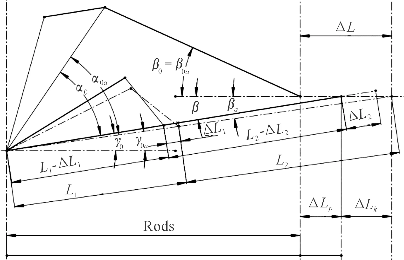
Fig.5Togglemechanismconsideringdeformationofcompressiondeformation.
(1) The deformation rodL1,L2along the long direction of the rod:
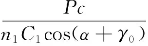
When the system starts to deform, toggleL1,L2stress as shown in Fig.6,Pcis the system of deformation force, by the compression deformation of ΔL1and ΔL1. According to Fig.6,L1,L2along the rod length direction respectively:
(17)
(18)

(19)
The parametersγ0is unknown,γ0for clamping in place when theL1andL2collinearL1,L2, and horizontal Angle,γ0can be calculated by the following formula.
From Fig.6, you can see that when clamping in place,Pc=Fm=500 kN,α=0,β,γ= 0,L1,L2, and the compression deformation of ΔL1, ΔL2, are respectively:

(20)
(21)
Among them

(22)
E1=2.09×10⁵N/mm2,E2=1.62×105N/mm2,S1=2 080 mm2,S2=5 257.08 mm2,n1=4,n2=2.
For each parameter, equations (2-21), (2-22), (2-23) were implemented in MATLAB, yielding the following solutions: ΔL1=0.034 mm, ΔL2=0.06 mm,γ0=3.95, and the compression deformation lengthL1′=158-0.034=157.96 mm mold in place before the elbow and the large rod,L2′=205-0.06= 204.94 mm.
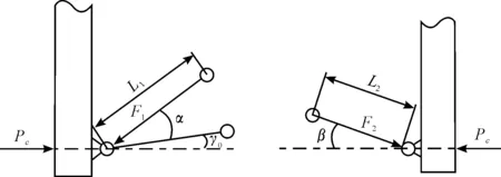
Fig.6 L1, L2 to toggle force diagram.
(2)The determination of the critical Angleα0
By Fig.2 to Fig.12 triangle available:
(L1′+L2′)cosγ0-[L1cos(α0+γ0)+L2cosβ0]=ΔLP
(23)
(24)
To the known parameters, by formula (15), (23), (24):α0=3.32 calculation.
3 Locking Mechanism of ADAMS Modeling
The establishment of the toggle mechanism is based upon a simplified model in ADAMS software. According to the closing position of each toggle mechanism is in place before die, bending the elbowL1and toggle the intersection ofL3A for the origin, the calculated coordinates of each rod endpoint are shown in Table 2.
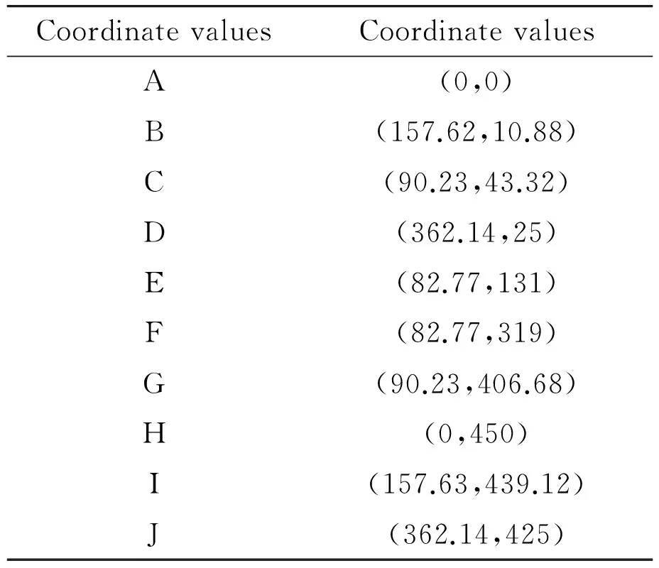
Table 2 Toggle lever mechanism endpoint coordinates.
According to the structure of the toggle mechanism, geometry connected with each marker establishes the toggle mechanism. The geometry is relatively independent due to the need to establish the constraint relationship motion pair in order to establish various geometric bodies. According to the elbow movement form, add a rotating pair in each connectingrod hinge, with a total of 10. In the connecting rod crosshead of the representative 1 add them side relative to the ground. With respect to the moving platen toggle 2, add the mobile side relative to the ground. Get mechanism of toggle mold in place when the modelas shown in Fig.7. Fig.7 represents toggle, Dalian 2 rod, 3 said the template, 4 said the small connecting rod,cross head of 5 represents.
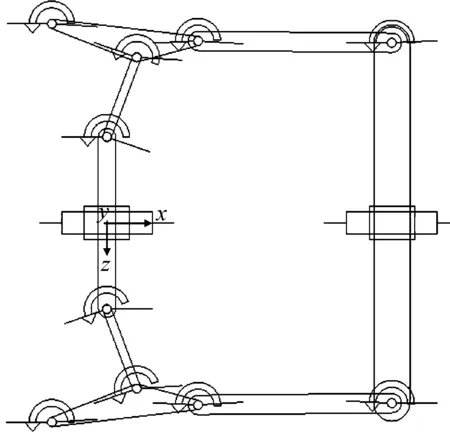
Fig.7ADAMSsimulationmodelofelbowbarmechanism.
3.1Theclampingmechanismkinematicssimulation
Applying linear clamping motion in the cross head, speed is set to 100 mm/s, the simulation time is set to 2.5 s, and the simulation step number is set to 2500.The calculation of dynamic template displacement, cross head displacement, and dynamic template velocity curves are shown in Fig.8. The curves of 1 and 2 respectively are the dynamic template and crosshead displacement simulation curve, and curve 3 is the dynamic template speed simulation curve.
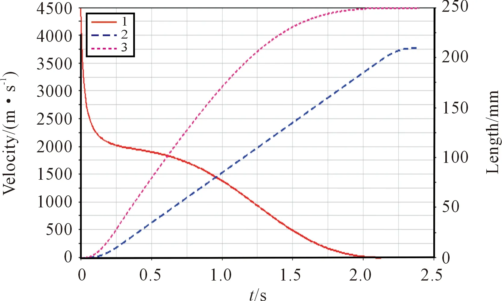
Fig.8Dynamictemplateandcrossheadsimulationcurve(1).
We can see from Fig.8 that the moving platen displacement is 250 mm, cross head displacement is 213 mm, the trip is about 1.17, with those of theoretical calculation, meet the requirements. When the time for more than 1.2 s, the movable template gradually approaching the clamping position, the movable template speed gradually become smaller and eventually reduced to 0. But due to the applied in the cross head speed is constant, so the speed curve of initial value is not 0, not completely in line with the actual change template speed. In the actual movement, the cross head speed at the beginning and the end stages of the process experience acceleration and deceleration. In order to simulate the actual motion process, as shown in Fig.9, the 0 s to 0.3 s cross head speed was accelerated from 0 to 100 mm/s, the 0.3 s to 2.1 s cross head followed uniform motion with a velocity of 100 mm/s, and from 2.1 s to 2.4 s, the cross head speed decelerated from 100 mm/s down to 0.
The simulation results shown in Fig.10 show that in the beginning stages, dynamic template speed increases to the maximum value, and maintains high speed movement.
When the mold is about to end, the movable template velocity decreases to the final 0. The dynamic changes of velocity template with slow-Fast-slow speed requirements, which causes the change and displacement curve to be smooth with no mutation, helps to reduce the dynamic template impact vibration phenomenon. The dynamic template maximum speed is 215.34 mm/s, and the rotating speed of the template and the cross head is 2.15.
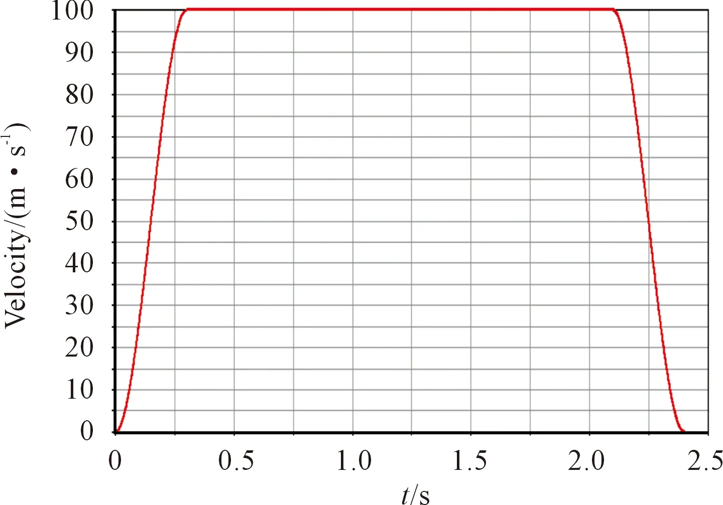
Fig.9 Cross head application acceleration curve.
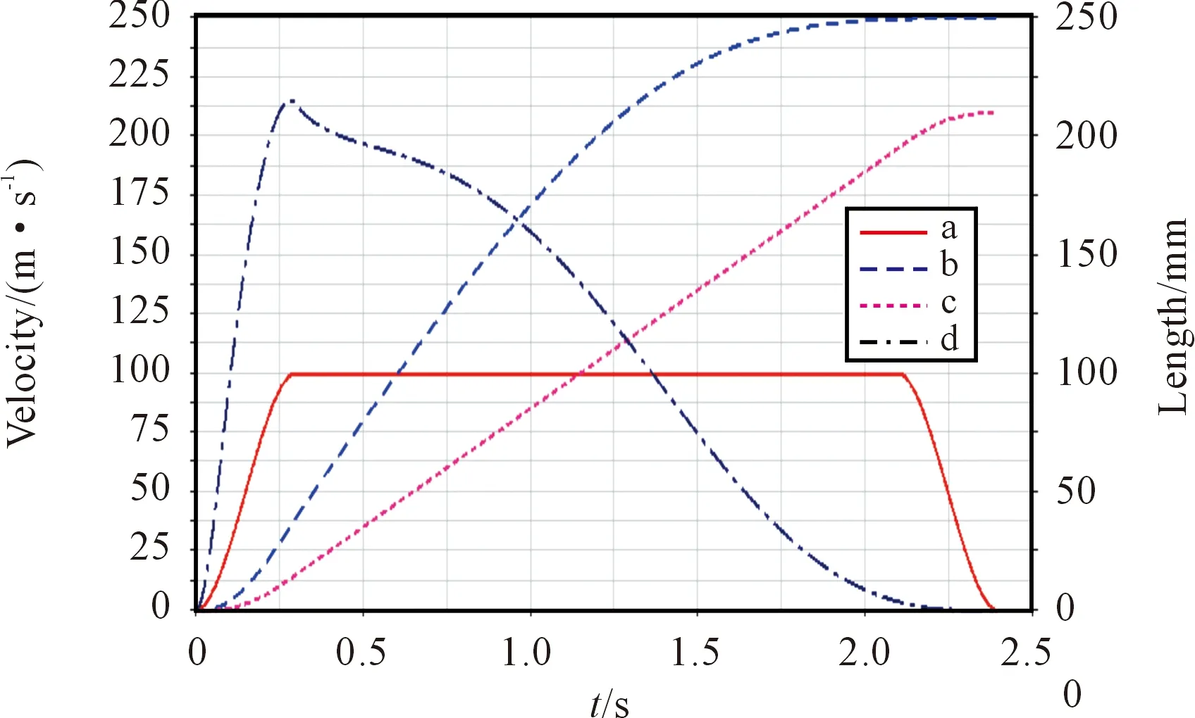
Fig.10Dynamictemplateandcrossheadsimulationcurve(2).
3.2Theclampingmechanismdynamicssimulation
When the dynamic template in the mold parting surface junction, namely elbow angleα, reaches the critical angleα0, clamping institutions begin to produce elastic deformation. Since the clamping force is equal to the magnitude of the deformation force of the pull rod clamping mechanism produced by the deformation of many factors, the decision to produce clamping force after moving template displacement by the toggle deformation, mold deformation etc. The simulation of mold clamping force, therefore, can use a spring to simulate the calculation of clamping force. A spring of elastic stiffness is equal to the system’s total stiffnessK, spring deformation ΔLis equal to the system, the type:
ΔL=ΔLp+ΔLk
(25)

(26)
This showed thatK=1.068×10⁶N/mm and ΔL=0.47 mm. At the start deformation in the mold clamping mechanism, the dynamic template displacement is equal to the system of deformation. The spring starting position for clamping in place when the moving distance template 0.47 mm position, the position for the elbow angleαvalue reaches the critical angleα0, clamping mechanism is started when in the deformation position, as shown in Fig.11.
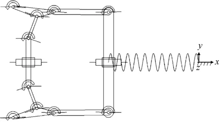
Fig.11 Clamping mechanism dynamics simulation model.
In crosshead applied acceleration is 10 mm/s by uniform motion, the simulation results shown in Fig.12. When the crank angle value is less than the critical angleα0, the locking mechanism begins deformation mold clamping force. As the elbow angle becomes smaller, the movable template gradually approaches the clamping position, and the clamping force becomes larger. When the mold is complete, i.e., elbow angleαis equal to 0, the mold closing force reaches the maximum value 500 kN, which agrees with the theoretical calculation and design objectives.
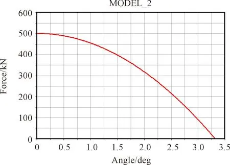
Fig.12 Clamping force simulation curve.
4 Conclusion
Mathematical model of clamping mechanism is established to obtain the micro structure of injection molding machine stroke ratio of 1.15, faster than the 4.49, force magnification ratio in crankshaft angle alpha is 3 DEG to 20.37. From the analysis of deformation of locking mechanism, the diagonal and the critical angle alpha 0 gamma 0 calculation equations were used to calculate the exact value: diagonal gamma 0 is 3.95 degrees, the critical angle alpha 0 to 3.32 degrees. We obtained through dynamics simulation analysis, dynamic template displacement is 250 mm, the cross head displacement is 213 mm. Through modifying cross head speed function, dynamic template maximum speed is 215.34 mm/s, the moving speed of the template and the cross head is 2.15. Finally, by setting spring, which represents the locking mechanism for dynamic simulation of elastic, the clamping mechanism of the deformation curve of mold clamping force, to the maximum value of 500 kN, which is consistent with the values and the design target and theoretical calculation. Mold is a traditional subject but remaining advanced engineering challenges, governed by various mechanics/physics rules. Mathematical model design solutions have been conducted and applied for the development of injection molds, allowing for intelligent parts manufacturing used in robots, automates and other machineries. Also with precise model design, the molds can serve well with the multi-possibilities to achieve intelligent manufacturing. Such system analysis, modeling and integration can ultimately serve the goal of develop next generation intelligence machining such as intelligent sensing[24-29]and offer advanced mold design system to fulfill the complexity of various industrial needs such as aircrafts, automotives, maritime parts, etc..
Acknowledgment
This publication was made possible by funding from the National Science Foundation (HRD 1700429) and NIMHD-RCMI grant number 5G12MD007595 from the National Institute of Minority Health, Health Disparities and the NIGMS-BUILD grant number 8UL1GM118967.
[1]M.Packianather, F.Chan, C.Griffiths, S.Dimov, and D.T.Pham, Optimisation of Micro Injection Moulding Process through Design of Experiments,ProcediaCIRP, vol.12,pp.300-305, 2013.
[2]Z.Y.Liu, N.H.Loh, S.B.Tor, K.A.Khor, Y.Murakushi, and R.Maeda, Binder system for micropowder injection molding,MaterialsLetters, vol.48, no.1,pp.31-38, 2001.
[3]S.Engleder, Time-optimal motion planning and control of an electrohydraulically actuated toggle mechanism,Mechatronics,vol.17,no.8,pp.448-456, 2007.
[4]B.Sha, S.Dimov, C.Griffiths, and M.S.Packianather,Investigation of micro-injection moulding: factors affecting the replication quality,JournalofMaterialsProcessingTechnology,vol.183,no.2,pp.284-296, 2007.
[5]G.Wang, H.Chen, and F.Li, Researchon potimization design of double-toggle clamping unit for injection molding machine,EngineeringPlasticsApplication, vol.39,no.5,pp.87-90, 2011.
[6]M.S.Huang, T.Y.Lin, and R.F.Fung, Key design parameters and optimal design of a five-point double-toggle clamping mechanism,AppliedMathematicalModelling, vol.35,no.9, pp.4304-4320, 2011.
[7]D.Q.Gao and Z.G.Guo,SimMechanics based on the injection molding machine and the optimization of design simulation,MachineryDesign&Manufacture, no.4, pp.82-84, 2009.
[8]Y.G.Zhang, Researches on speed-transmission ratio of double-toggle clamping mechanism,BeverageIndustry,vol.12,no.9,pp.34-41, 2009.
[9]W.Y.Lin and K.M.Hsiao, Investigation of the friction effect at pin joints for the five-point double-toggle clamping mechanisms of injection molding machines,InternationalJournalofMechanicalSciences,vol.45,no.11,pp.1913-1927, 2003.
[10] S.P.Zhong, Research on Kinematics Simulation of the Double-toggle Clamping Mechanism for Injection Molding Machine,EquipmentManufacturingTechnology, no.3,pp.6-7,10, 2010.
[11] Z.N.Shao, A.N.Ying, P.C.Xie, Y.M.Ding , and W.M.Yang, Design and Optimization Analysis for Hybrid-drive Clamping Unit of All-electric Injection Moulding Machine Based on ADAMS Software,ChinaPlasticsIndustry,vol.38,no.8,pp.47-49,53,2010.
[12] W.Zheng,SimulationAnalysisandExperimentResearchofProcessinMicroInjectionMolding.Dalian University of Technology, 2006.
[13] U.M.Attia, S.Marson, and J.R.Alcock, Micro-injection moulding of polymer microfluidic devices,MicrofluidicsandNanofluidics, vol.7,no.1,pp.1-28, 2009.
[14] V.Piotter, A.Guber, and M.Heckele, A Gerlach Micro injection moulding of medical device component,BusinessBriefing,London:MedicalDeviceManufacturing&Technology, 2002, pp.63-66.
[15] A.Ameli, Y.Kazemi, S.Wang, C.Park, and P.Pötschke,Process-microstructure-electrical conductivity relationships in injection-molded polypropylene/carbon nanotube nanocomposite foams,CompositesPartA:AppliedScienceandManufacturing, vol.96, pp.28-36, 2017.
[16] B.Kumar, M.Doddamani, S.E.Zeltmann, N.Gupta, M.Ramesh, and S.Ramakrishna, Processing of cenosphere/HDPE syntactic foams using an industrial scale polymer injection molding machine,Materials&Design, vol.92, pp.414-423, 2016.
[17] S.M.Aqeel, Z.Huang, J.Walton, C.Baker, D.Falkner, Z.Liu,and Z.Wang, Polyvinylidene fluoride (PVDF)/polyacrylonitrile (PAN)/carbon nanotube nanocomposites for energy storage and conversion,AdvancedCompositesandHybridMaterials, DOI: 10.1007/s42114-017-0002-5, 2017.
[18] H.Wei, H.Gu, J.Guo, X.Yan, J.Liu, D.Cao, X.Wang, S.Wei, and Z.Guo, Significantly Enhanced Energy Density of Magnetite/Polypyrrole Nanocomposite Capacitors at High Rates by Low Magnetic Fields,AdvancedCompositesandHybridMaterials, DOI: 10.1007/s42114-017-0003-4, 2017.
[19] F.Kroschwald, J.Nagel, A.Janke, F.Simon, C.Zimmerer, G.Heinrich, and B.Voit,Gold nanoparticle layers from multi-step adsorption immobilised on a polymer surface during injection molding,JournalofAppliedPolymerScience, vol.133,pp.1-8,2016.
[20] M.G.Battisti, W.Friesenbichler, I.Duretek, and P.Guttmann,Correlation between Rheotens measurements and reinforcement of polymer nanocomposites in the injection molding compounder,JournalofPhysics:ConferenceSeries, vol.602,no.1,pp.1-8,2015.
[21] W.Zhang, X.He, C.Li, X.Zhang, C.Lu X.Zhang, and Y.Deng, High performance poly (vinyl alcohol)/cellulose nanocrystals nanocomposites manufactured by injection molding,Cellulose, vol.21,pp.485-494,2014.
[22] Y.Ma, L.Lyu, Y.Guo, Y.Fu, Q.Shao, T.Wu, S.Guo, K.Sun, X.Guo, E.K.Wujcik, and Z.Guo, Porous lignin based poly (acrylic acid)/organo-montmorillonite nanocomposites: Swelling behaviors and rapid removal of Pb (II) ions,Polymer, vol.128,pp.12-23, 2017.
[23] Z.Liu, Z.Huang, F.Cheng, Z.Guo, G.Wang, X.Chen, and Z.Wang, Efficient Dual-Site Carbon Monoxide Electro-Catalysts via Interfacial Nano-Engineering,ScientificReports, vol.6,pp.1-11, 2016.
[24] C.Alippi, A unique timely moment for embedding intelligence in applications,CAAITrans.Intellig.Technol., vol.1, no.1,pp.1-3,2016.
[25] H.Jin, Q.Chen, Z.Chen, Y.Hu, and J.Zhang, Multi-Leap Motion sensor based demonstration for robotic refine tabletop object manipulation task,CAAITrans.Intellig.Technol, vol.1,no.1,pp.104-113, 2016.
[26] K.Sun, P.Xie, Z.Wang, T.Su, Q.Shao, J.Ryu, X.Zhang, J.Guo, A.Shankar, J.Li, R.Fan, D.Cao, and Z.Guo, Flexible polydimethylsiloxane/multi-walled carbon nanotubes membranous metacomposites with negative permittivity,Polymer, vol.125, pp.50-57, 2017.
[27] X.Zhang, H.Gao, M.Guo, G.Li, Y.Liu, and D.Li, A study on key technologies of unmanned driving,CAAITrans.Intellig.Technol,vol.1, no.1, pp.4-13, 2016.
[28] S.Padhy and S.Panda, A hybrid stochastic fractal search and pattern search technique based cascade PI-PD controller for automatic generation control of multi-source power systems in presence of plug in electric vehicles,CAAITrans.Intellig.Technol,vol.2, no.1,pp.12-25, 2017.
[29] X.Guan, G.Zheng, K.Dai, C.Liu, X.Yan, C.Shen, and Z.Guo, Carbon Nanotubes-Adsorbed Electrospun PA66 Nanofiber Bundles with Improved Conductivity and Robust Flexibility,ACSAppl.Mater.Interf., vol.8, no.22, pp.14150-14159, 2016.
•Zhiming Jin,Yajun Zhang, Liqun Dong,and Jian Zhuang are with College of Mechanical and Electrical Engineering, Beijing University of Chemical Technology, Beijing 100029, China. E-mail: zhuangjian@mail.buct.edu.cn
•Xinliang Wang and Gang Zhou are with Ningbo L.K. Technology Co. Ltd, Ningbo 315806, China.
•Jacob Williams and Zhen Liu are with Department of Physics and Engineering, Frostburg State University, Frostburg, MD 21532, USA.
•Jacob Williams is with Department of Mechanical Engineering, University of Maryland, College Park, MD 20742, USA.
•Zhongyuan Huang, D’Lauren Falkner,and Zhe Wang are with Chemistry Department, Xavier University of Louisiana, New Orleans, LA 70125, USA. E-mail: zwang@xula.edu.
•Zhongyuan Huang is with College of Chemistry and Chemical Engineering, Xinyang Normal University, Xinyang 464000, China.
*To whom correspondence should be addressed. Manuscript
2017-08-10; accepted:2017-09-15
杂志排行

CAAI Transactions on Intelligence Technology的其它文章
- Interactions Between Agents:the Key of Multi Task Reinforcement Learning Improvement for Dynamic Environments
- Technology and Application of Intelligent Driving Based on Visual Perception
- Technology of Intelligent Driving Radar Perception Based on Driving Brain
- Enriching Basic Features via Multilayer Bag-of-words Binding for Chinese Question Classification
- The Fuzzification of Attribute Information Granules and Its Formal Reasoning Model
- Retinal Image Segmentation Using Double-Scale Nonlinear Thresholding on Vessel Support Regions