一种应用于城区低风速环境下的小型风力发电并网逆变系统
2017-09-15张纪杰
张纪杰
(国网山东省电力公司淄博供电公司,山东 淄博 255032)
一种应用于城区低风速环境下的小型风力发电并网逆变系统
张纪杰
(国网山东省电力公司淄博供电公司,山东 淄博 255032)
目前,制约商用小型风力发电系统发展的最大弊端是其转换效率低,风力发电输出大多被系统自身所消耗、风能有效利用率低。为充分利用在城区环境中低风速环境下的风能,有针对性地设计了一款并网逆变器,并在拓扑结构与控制策略上都做了改进性设计,以提高系统对低风速风能的利用效率。该系统在并网同时必须要考虑变换硬件电路对于风能的利用率,系统的前级部分采用BOOST型硬件电路进行分段式调节,以实现低风速下风能的最大功率输出;后级电路部分采用改进型的逆变结构,以配合BOOST电路完成整体设计功能的实现。经实验结果分析,设计的系统运行性能优越,在低风速下能向电网输送高质量电能。本系统相较于传统商用小型风力发电并网逆变器在工作性能上有了大幅提升,对于小型风力发电系统的推广,清洁能源的有效利用具有重要的研究意义和现实意义。
风力发电;城区低风速环境;并网逆变;风能利用率
0 Introductions
Wind energy as an important source of clean energy,its development and utilization has attracted a lot of attentions.At present,the commercial operation mode has been used in the small wind power grid in verter system[1].However,the low efficiency,unsatisfactory performance under low wind speed limited the application of the traditional commercialmode[2].Thewind power is largely consumed by the inverter itself under low wind speed[3].To improve the performance of the small wind power generation under low wind speed and increase the energy utilization,a new inverter is proposed in this paper.
The two-stage circuit with isolation transformer topology was adopted in this paper.The fluctuant DC from the rectifier was filtered by the LC circuit to stable DC by the former main circuit[4].The topology of aftermain circuitwas designed as a single-phase,full bridge invertercircuit[5].The output AC voltage of the inverter can be transformed to match the required voltage for connecting to the grid by the isolationtransformer.The advantage of this design is that the DC link voltage which determines the output voltage can be smaller so that the utilization of the wind energy under low wind speed is increased[6].The purpose of improving the utilization rate of wind power can be realized.
1 The Main Circuit Topology of S inglephase Grid Inverter
The overall system configuration is as shown in Fig.1.The connection of the sub-systems including the turbine and generator module,discharging protection,rectifier,boost converter,single-phase full-bridge inverter and the isolation transformer are clearly shown.
The three-phase AC from wind turbineswas converted to DC by the passive rectifier.The DC-to-DC conversion is introduced in order to control the voltage of the capacitor connected to the passive rectifier so that the circuit achieved energy maximum power point tracking(MPPT).The DC was changed to AC by the single-phase full-bridge inverter.An L type filter is used to eliminate the high order harmonics caused by the switching in the output power.
The low input DC voltage Udcwas boosted to the higher output side of the Ubusby the boost conversion circuit.At present,the traditional commercial grid inverter output side is non-isolated grid structure[7-10].In the conventional inverter topology;the inverter output voltage is 220 V which requires the DC bus voltage to be higher than 400 V.To ensure the current flow to be continuous,the booster duty ratio is designed to vary within the range from 0.2 to 0.9.Therefore DC input voltagemust be greater than 40 V.The starting voltage of the traditional commercial grid inverter is usually 50~70 V.So the traditional commercial grid inverter can't use the low wind speed of wind.The turnsratio was designed as 1∶2 in this system.The output voltage can be reduced to 110 V while the bus voltage can be reduced to 300 V.Thus the starting voltage of the low voltage DC side can be reduced to 30 V.In order to balance the energy consumption of the inverter with the efficiency of the power output,the starting voltage was designed as 40 V.Therefore,this system can make better use of the energy with low wind speed.
2 The MPPT Control Algorithm
It is difficult to promote the use of the smallwind power generation system in most urban areas for the low wind speed.The problem can be solved in this paper.When the wind speed is low which is not usable by the conventional system,the Udccan be improved to make the inverter working normally.The MPPT control algorithm is adopted to ensure the efficiency of the system under higher wind speed.So this system is adaptive to a large range of thewind speed.

Fig.1 Topology of the smallw ind power system
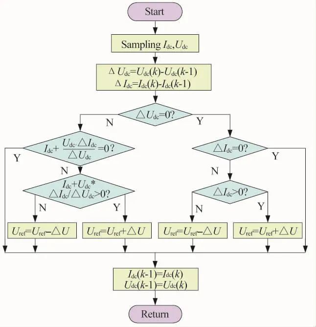
The MPPT can be carried out by any of the following two algorithms:the disturbance observation method and the conductance incrementalmethod.The conductance incrementmethod takes sample of the input voltage and output current as the control feedback.The control signal can be altered by comparing the conductance increment and instantaneous conductanceof the input voltage.The biggest advantage of this method is that the output voltage can follow the change of the input voltage smoothly.It is suitable for the small wind power applications applied in the rapidly changing atmospheric conditions.The conductance incrementalmethod is chosen for carrying out the MPPT in the system proposed.The MPPT control flow chart is showed in Fig.2.

Fig.2 Control flow chartof MPPT
3 The Control Method of the Grid-connected Inverter
3.1 The output current control of the grid-connected inverter
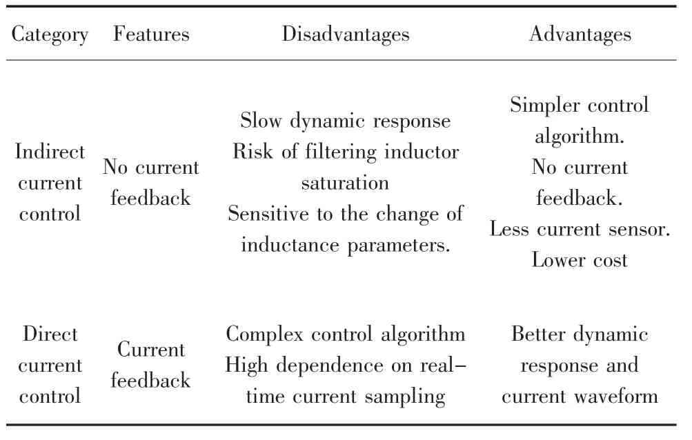
The output current control can be categorized into indirect current control and direct current control differed by if there is current feedback.The characteristics of these two of controlmode were showed in table 1.The direct current control was adopted in this system design.

Table 1 Classification and characteristics of current control technology
The double closed loop control is used in this system.The double closed loop control includes an outer voltage control loop and inner current control loop.The outer voltage control loop serves the purpose of stabilizing the DC bus voltage by generating the reference current so that the input and output power of the DC bus can be balanced.The inner current control loops in charge of adjusting AC side voltage command signals by comparing the real-time current samples and the current reference value.The PWM signals are generated following the voltage command signals to control the switching action of the power electronic devices.The control of the amplitude and phase of the current injected into the grid can be achieved.The controller block diagram is as shown in Fig.3.

Fig.3 Controlblock diagram of the double closed-loop
The design of the inner current control loop is essential to determine the overall control performance.The difference between the current reference I*Land actual current ILis compared with the triangular carri-er wave as the modulation wave.The output SPWM control signal ismagnified through the gate drive circuit to drive power switch tube.At last,the sinusoidal current with the same frequency of the power grid is produced after filtering.
3.2 The control principle of the sine wave instruction current
The phase-lockingmechanism is required to keep the current reference having the same frequency and phase angle to the grid voltage.It is designed in this paper aided by software design tool.The triangular wave comparison control method was adopted in this paper for the generation of SPWM waveform.The comparison of software implementation method for SPWM was as shown in table 2.

Table 2 Com parison of software im plementation method for SPWM
The synchronousmodulation was adopted in this paper according to the requirements of the system control performance.Unipolar sampling method and bipolarmodulation were adopted in this paper.
4 Control Flow Chart and Experimental Results
4.1 Control flow chart
As the real-time control requirements for the system is strict,the system software is divided into main program and interrupt service subroutine to distribute the computational burden evenly so that the program efficiency is improved.The routine with less real-time requirement is placed in the main program loop while the routine requiring smaller step size is placed in the interrupt service subroutine.So the real-time performance and efficiency of the grid-connected control is ensured.
Themain program works as an infinite loop.The initialization of the special register and the external event manager register is the primary function of the main program.The main program can detect system state periodically.The interrupt service routine mainly includes T1 cycle interrupt subroutine,T1 underflow interrupt subroutine and the capture of interrupt subroutine.The flow charts of the main program and the interrupt service subroutine are as shown in Fig.4.
4.2 R esults of system experiment
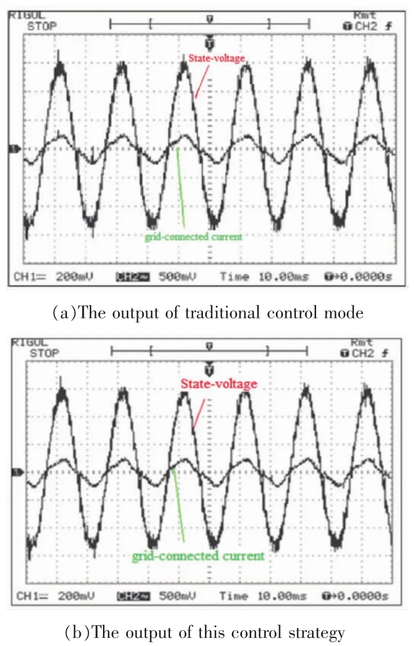
The experimental test has been carried out to verify the performance of the proposed system operating under low wind speed.The outputwaveform for the above two kinds of inverter is showed in Fig.5.
It is clear that the current injected into the grid as shown in Fig.5(a) is ata desired value.This current is achieved when the DC side voltage is 70 V which is a standard minimum voltage level for conventional small wind power generation to operate.The current waveforms shown in Fig.5(a) and Fig.5(b) are identical.However,the DC side voltage for the two cases is different.The currentwave form shown in Fig.5(b) is achieved when the DC side voltage is only 50 V.As the DC side voltage is directly linked to the wind speed in such a system topology,operating under lower DC side voltage means capable of utilizing smaller winds.The conventional small scale wind power generation will be automatically disabled when the wind is not able to sustain the DC voltage above 50 V.In contrast,the system designed presented in this paper can make full use of the wind power under low speed.The ability to utilize the wind power under low speed improves the performance of the small wind power grid-connected inverter.The design objective is full-filled.However,the low order harmonics wasunable to avoid in a current waveform when the DC voltage has not been sampled in the current control section.It can be improved in the follow-up research.

Fig.4 Flow charts ofmain program and interrupt service subroutine

Fig.5 Analysis and comparison for the output result
5 Conclusions
A small wind power single-phase grid-connected inverter which is committed to make better use of the wind power under low speed and applied in urban areas is designed in this paper.The topology and control strategy have been improved.The experimental study has been carried out via a prototype.From the experimental results,the conclusion can be obtained that the inverter designed presented in this paper can make better use of the wind power under low speed.The test performancemeets the design requirements.
References
[1]XU Po,ZHANG Xing,ZHANG Chongwei,et al.The small wind grid inverter control system design based on the BOOST converter[J].ActaEnergiae Solaris Sinica,2007,28(3):274-279.
[2]WEN Chunxue,SUN Fengfang,LIZhengxi.The research of single-phase grid inverter control strategy for the small and medi um-sized wind power generation system[J].Renewable Energy Resources,2011,29(5):36-40.
[3]ZMOOD D N,HOLMESD G.Stationary frame current regulation of PWM inverters with zero steady-state error[J].IEEE Transactions on Power Electronics,2003,18(3):814-822.
[4]ZHAOQinglin,GUO Xiaoqiang,WUWeiyang.The research of the single phase inverter grid control technology [J].Preceeding of the CSEE,2007,27(16):61-64.
[5]CHEN Jidong,SHI Chongyang,ZHOU Leyi.Single-phase sine wave active grid inverter[J].Electronic Design Engineering ,2011,19(13):187-192.
[6]CHENYM,HUNGSC,CHENGCS,et al.Multiinput inverter for grid-connected hybrid PV /wind power system [C]∥APEC 2005,20th Annual IEEE,2005,2: 850-856.
[7]MAYoujie,CHENGDeshu,CHEN Lan,etal.The analysis and research of PV grid inverter[J].Electric Drive,2009,39(4):25-26.
[8]CHENG Junzhao,WU Xike,LI Pengsen,et al.The two levels of photovoltaic grid-connected inverter system with Boost[J].High Voltage Engineering,2009,35(8):2 048-2 052.
[9]MILOSEVIC Mirjana,ALLMELING Jost,ANDERSSON Goran.Interaction between hysteresis controlled inverters used in distribut ed generation systems[C]∥IEEE Power Engineering Society General Meeting,Denver,Colorado,USA,2004.
[10]LIU Fengjun.Environmental protection energy-saving H bridge&SPWM inverter DC power supply[M].Beijing:Electronic Industry Press,2010.
Accepted date:2017-04-29
ZHANG Jijie(1986),male,master.His research direction is the grid-connectedmanagement of new energy.
The Small W ind Power Grid-Connected Inverter System Applied to Urban Areas w ith Low W ind Speed
ZHANG Jijie
(State Grid Zibo Power Supply Company,Zibo 255032,China)
At present,the efficiency of small commercial wind power grid inverter is low.The output of this type of wind power generation is largely consumed by itself.In order to make full use of the wind energy contained in the low speed wind in the urban areas,we propose some improvements on the topology and control strategy of the smallwind power generation to solve the problem of low efficiency.The sectional adjustment is adopted in the control of BOOST circuit to improve the efficiency of the energy conversion.An improved topology is adopted in the inverter stage to cooperate with the BOOST circuit and full-fill the design objectives.After experimental verification,the performance of the grid-connected inverter device used in low wind speed is proved to be superior and the quality of the energy is excellent.This research has great significance to promote wind power generation system and make full use of renewable clean energy.
wind power generation;urban areaswith low wind speed;grid-connected inverter;the utilization ofwind power
TM614
:A
:1007-9904(2017)08-0013-06
