A real-time 5/3 lifting wavelet HD-video de-noising system based on FPGA①
2017-06-27HuangQiaojie黄巧洁LiuJiancheng
Huang Qiaojie (黄巧洁), Liu Jiancheng
(Department of Mechanics and Electricity, Guangdong Agriculture Industry Business Polytechnic, Guangzhou 510507, P.R.China)
A real-time 5/3 lifting wavelet HD-video de-noising system based on FPGA①
Huang Qiaojie (黄巧洁)②, Liu Jiancheng
(Department of Mechanics and Electricity, Guangdong Agriculture Industry Business Polytechnic, Guangzhou 510507, P.R.China)
In accordance with the application requirements of high definition (HD) video surveillance systems, a real-time 5/3 lifting wavelet HD-video de-noising system is proposed with frame rate conversion (FRC) based on a field-programmable gate array (FPGA), which uses a 3-level pipeline paralleled 5/3 lifting wavelet transformation and reconstruction structure, as well as a fast BayesShrink adaptive threshold filtering module. The proposed system demonstrates de-noising performance, while also balancing system resources and achieving real-time processing. The experiments show that the proposed system’s maximum operating frequency (through logic synthesis and layout using Quartus 13.1 software) can reach 178MHz, based on the Altera Company’s Stratix III EP3SE80 series FPGA. The proposed system can also satisfy real-time de-noising requirements of 1920×1080 at 60fps HD-video sources, while also significantly improving the peak signal to noise rate of the de-noising images. Compared with similar systems, the system has the advantages of high operating frequency, and the ability to support multiple source formats for real-time processing.
video surveillance, threshold filtering, discrete wavelet transformation (DWT), field-programmable gate array (FPGA), de-noising
0 Introduction
The performance of sampling devices, signal transmission channels, and other factors may cause noise to be added to video images in video surveillance systems. The addition of noise degrades the display quality of the images and affects subsequent analytical processing. As such, the ability to remove noise in real-time is critical to enhancing video quality. With the continuous developments of high definition (HD) signal processing technology, quantities of video data, as well as types of video sources, are increasing. Different signal sources vary in their video formats, which lead to different output resolutions from decoder chips and different pixel clock frequencies. Therefore, video surveillance systems require real-time processing with frame rate conversion for multiple signal source formats.
Presently, there are 3 types of hardware platforms for implementing real-time video de-noising: (1) application specific integrated circuit (ASIC) platforms, (2) digital signal processor (DSP) platforms, and (3) field-programmable gate array (FPGA) platforms. The ASIC platform has a high operating frequency and strong real-time processing ability; however, it requires a longer design cycle and lacks flexibility in online programming. Due to the limitation of instruction execution of the DSP core processing structure and the main frequency, the DSP-based system is deficient in processing HD-video in real-time as it takes a long time to deal with large amounts of image data. The FPGA-based implementation can be programmed online, processed in parallel, and achieve real-time performance and low-power consumption, which is an improvement over both the DSP and ASIC systems[1]. As such, the FPGA systems have garnered more attention and research.
For instance, Katona, et al.[2]presented a real-time implementation of wavelet video de-noising by using 2 FPGA chips operated alternately in order to realize wavelet decomposition and reconstruction. By utilizing a ping-pong storage method and an operating mechanism based on FPGA, Ma[3]attained a processing result of 640×480 at 25fps. Ji, et al.[4]presented a real-time implementation of wavelet image processing using the Altera Stratix II series FPGA, which was able to process numerous image data in parallel, and achieve a processing effect of 320×240 at 50fps. Ning, et al.[5]implemented a dynamic random-access memory (RAM) structure inside an FPGA device for a 5/3 lifting wavelet, which was suitable for pre-processing, de-noising, and compression transmission for static images. Tang, et al.[6]presented an improved system using the Altera Stratix II FPGA based on paralleled row processing, which realized the 3-level 2-dimensional (2-D) 9/7 integer wavelet transformations for 1024×1024 at 100fps gray images under the operating clock frequency of 86.5MHz. Guo, et al.[7]presented a high performance and low memory discrete wavelet transformation (DWT) structure in JPEG2000, which was verified on a Xilinx FPGA platform. Its operating clock frequency reached 150MHz for 512×512 images and for wavelet decomposition. Wang, et al.[8]proposed a real-time system with 2-D lifting integer wavelet transformations using a very large scale integration (VLSI) structure based on row processing for satellite image encoding. The system was tested on a Xilinx FPGA platform and its highest operating frequency was above 115MHz. Finally, Wang, et al.[9]used a flipping structure and normalization steps in row and column DWT and rearranged data using a multiplexer in order to realize a 2-D 9/7 lifting wavelet VLSI structure in JPEG2000, with simulation frequency of up to 136MHz based on the FPGA.
The research for real-time video processing systems based on the FPGA platforms focuses on 2 areas: the first area is concerned with reducing hardware resource overhead in order to improve resource utilization efficiency. The second area is concerned with shortening the time delay of critical paths in order to improve the system’s operating speed. Liao, et al.[10]proposed a recursive algorithm which used the interdependencies between the wavelet coefficients by interleaving in order to calculate the higher level’s wavelet coefficients in the same data path in alternating clock cycles. The algorithm improved hardware utilization, but it caused high complexity in processing timing control, and more intermediate storage registers. Using the similarities between prediction and updating functions, Wu, et al.[11]merged the 2 steps together in order to increase operating frequency and reduce the consumption of the hardware resources. Shi, et al.[12]decomposed the serial operations of the lifting steps into many small steps, which shortened critical paths and lessened register consumption by using the correlation between the steps to re-arrange the calculation. Wu[13]proposed a 1-dimensional (1-D) multi-level pipeline architecture for a 9/7 lifting wavelet structure in order to shorten the time delay of critical paths; however, the method consumed too many registers. By using the abundant on-chip memories, ping-pong scheme, and serial pipeline, Chen, et al.[14]implemented a 5/3 lifting wavelet transformation which significantly reduced the number of registers in a 512×512 image. Todkar, et al.[15]proposed a pipelining and flipping structure with the overlapped strip based on scanning and calculation of the intermediate coefficients in order to shorten the time delay of critical paths.
In actual applications of video surveillance systems, consideration must be given to both delay of critical paths and hardware resources. In accordance with these requirements, a real-time 5/3 lifting wavelet HD-video de-noising system based on an FPGA is proposed which supports frame rate conversion (FRC), and realizes real-time de-noising for 1920×1080 at 60fps in HD-video for display.
1 System hardware framework
Altera Company’s Stratix III EP3SE80 series FPGA is based on 65nm processing technology, and is characterized by rich logic resources, the ability to support DDR2/DDR3 high-speed storage devices, high performance, and low-power consumption. Based on this FPGA hardware platform, this study proposes a real-time 5/3 lifting wavelet HD-video de-noising system with a frame rate conversion structure shown in Fig.1. The system contains the following components: a 3-level 5/3 lifting wavelet transformation, adaptive threshold filtering, a paralleled lifting wavelet reconstruction (also called wavelet inverse transformation), a frame buffer interface control module for frame rate conversion, and a memeory control module.
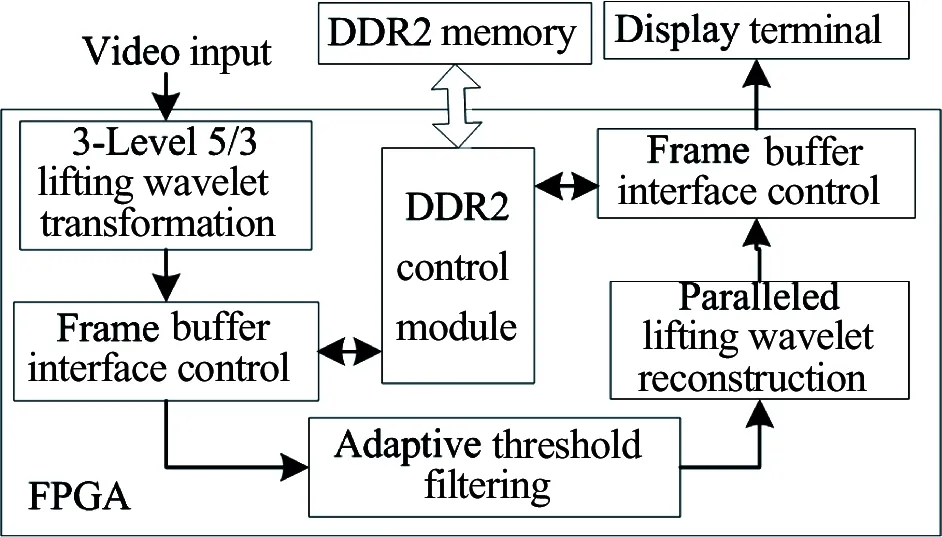
Fig.1 The block diagram of the proposed 5/3 lifting wavelet HD-video de-noising system
A 5/3 lifting wavelet transformation with a 3-level pipeline paralleled structure is selected to reduce serial computation and achieve real-time processing, and an adaptive threshold filtering is selected to remove noise. Generally, there are different signal source formats with different frame rates and pixel clock frequencies; however the display resolution of the display terminal remains fixed. Therefore, frame rate conversion is needed between the input and output terminals. When the output frame rate is lower than that of input, a corresponding number of frames need to be extracted between the input frames to achieve the required frame rate. Similarly, when the output frame rate is higher than the input frame rate, a corresponding number of frames need to be added to the input frames to achieve the required frame rate.
The implementation of frame rate conversion is shown in Fig.2 and contains the following parts:
(1) Synchronization processing for the input signals of HS_i (Horizontal Synchronous Signal), VS_i (Vertical Synchronous Signal), DE_i (Image Enable Signal), and PCLK_i (Pixel Clock Signal) to the corresponding output signals.
(2) A frame buffer part for input data. The frame buffer part needs to buffer at least 3 frames through the external DDR2 SDRAM memory.
(3) A logic control part for frame rate conversion. The logic control part buffers the reading and writing operations, and achieves frame rate conversion for output.
As mentioned above, the input and output signals may be asynchronous. The frame rate of the input signal can be greater than, equal to, or less than the frame rate of the output signal. Therefore, a frame buffer interface control module is designed in order to facilitate basic frame rate conversion processing. The reading and writing operation pointers’ control for frame rate conversion must meet the following rules: first, the faster frame pointer should wait for the slower frame pointer; second, the slower frame pointer needs to circulate freely; third, the current writing frame pointer is always the one previous to the current reading frame.
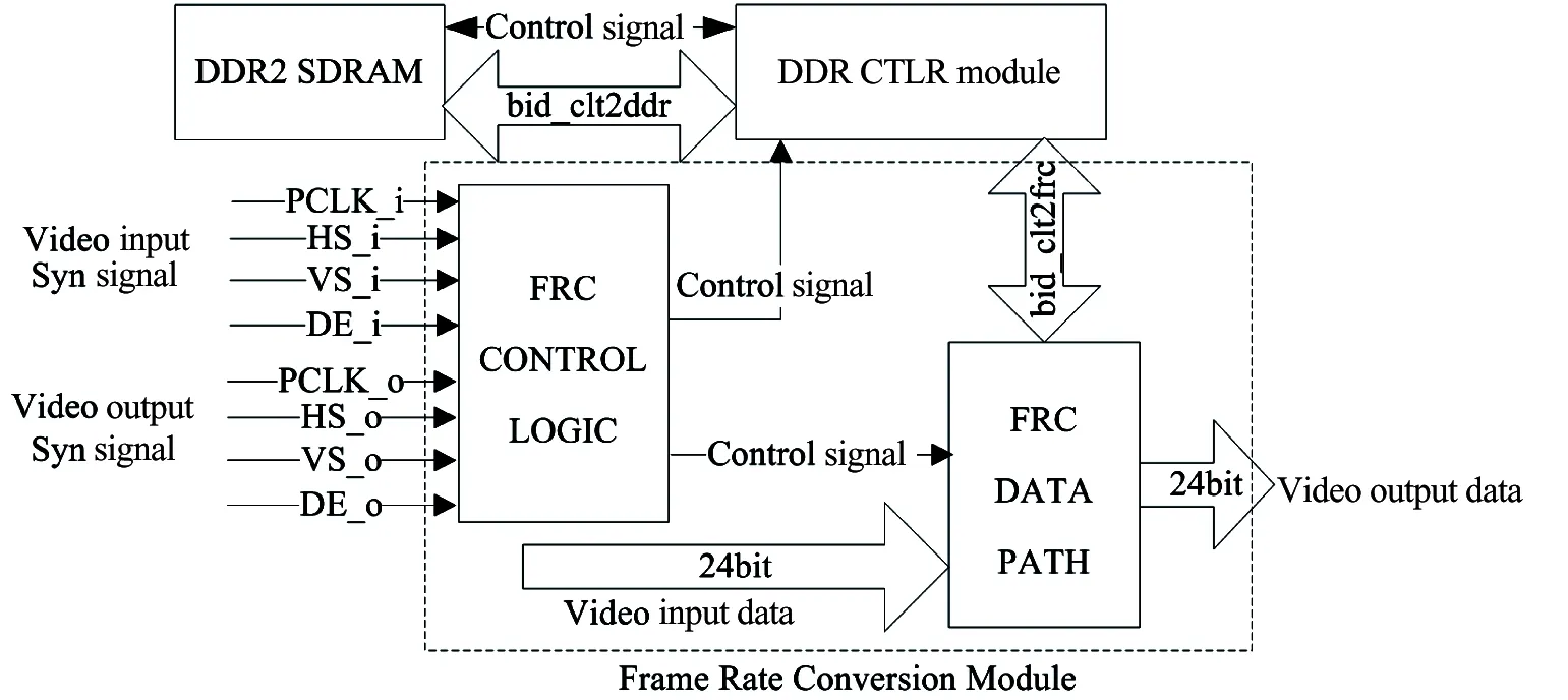
Fig.2 The module implementation for frame rate conversion
For a 1080p60 HD-video signal, the frame rate is 60fps, and each frame contains 1920×1080 pixels. The processing time for each pixel should be no more than 8ns. Considering the blanking region of the video images, actual processing time for each pixel should be no more than 6.7ns. Therefore, the minimum operating frequency for HD-video processing should be 148.5MHz.
In order to achieve real-time wavelet domain de-noising for HD-video of 1920×1080 24bits, at 60fps, 2 writing and 2 reading operations on DDR2 are needed. The required maximum throughput of DDR2 for HD-video of 1920×1080p60 is about 11.94Gbps. Assuming the access efficiency of 32-bit DDR2 is 80% and the clock frequency is 333MHz, the required bandwidth will be about 17.05Gbps, which is much larger than the required bandwidth of 11.94Gbps. Therefore, it meets the bandwidth requirement for real-time processing.
As such, the proposed system, which uses a DDR2 with a clock frequency of 333MHz, meets the clock frequency requirement for HD-video processing in real-time.
2 Implementations of key modules
2.1 Implementation of 1-D 5/3 lifting wavelet transformation
There are 2 kinds of wavelet transformations. The first one is the traditional wavelet transformation. The second one is the lifting wavelet transformation, where traditional wavelet transformation is based on the Fourier transformation, which utilizes very complex calculations. Importantly, the lifting wavelet transformation does not rely on the Fourier transformation; instead, it constructs the wavelet in the time domain and realizes integer to integer wavelet transformation. Moreover, the lifting wavelet transformation has the following advantages: high transformation speed; easy to be used in digital hardware circuits; and saving storage space for signal processing. Furthermore, the splitting structure before operating ensures that there are no redundant computations. Finally, wavelet reconstruction using the lifting wavelet transformation method can be obtained easily, which effectively reduces the power consumption of the entire system.
Generally, the lifting wavelet transformation is divided into 3 steps:
Step 1: Splitting. Divide the input sequencex(n)intoanoddsequencea(k)andanevensequenceb(k),whichcanbeexpressedby
a(k)=x(2n-1)
(1)
b(k)=x(2n)
(2)
Step2:Predicting.ConstructpredictionoperatorPandusepredictivevalueP(b(k))ofevensequenceb(k)topredicttheoddsequenceinordertoobtainhighfrequencyinformation,asshownby
c(k)=a(k)-P(b(k))
(3)
Step3:Updating.ConstructupdateoperatorUandupdatetheevensequencebyusingthepredictivehighfrequencyinformationtogetthelowfrequencyinformation,asshownbyEq.(4).
d(k)=b(k)+U(c(k))
(4)
ThespecificimplementationprocessfortheliftingwavelettransformationisshowninFig.3.

Fig.3 The lifting wavelet transformation process
The wavelet reconstruction is the inverse process of the lifting wavelet transformation. The process only needs to reverse the processing sequence, and change the operation sign of each step, as shown in Fig.4.
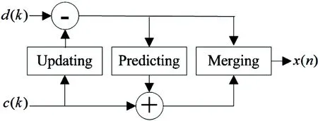
Fig.4 The lifting wavelet reconstruction process
In digital signal processing, the 5/3 integer lifting wavelet transformation is characterized by low computation. It is especially suitable for image compression and de-noising because the resources are limited but high processing speed is still required[16]. The equations for 5/3 integer lifting wavelet transformations are expressed as follows[17]:

(5)

(6)
Thesymbol⎣·」denotestheroundingoperation.x(2n+1)andx(2n)denotetheinputofoddandevensequences,respectively.y(2n+1)andy(2n)denotethehighandlowfrequencycoefficientsafterwaveletdecomposition.
Theformulasfor5/3liftingwaveletreconstructioncanbeexpressedas

(7)

(8)
Thedirectimplementationstructureofthe1-D5/3DWTispresentedinFig.5.
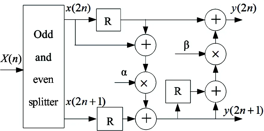
Fig.5 The block scheme of the 5/3 direct DWT: whereα=-1/2,β=1/4, and R denotes the register
After a thorough analysis of hardware implementations among direct structures, merged structures[11], and flipping structures, a folding and pipeline technique is adopted to best implement the 5/3 lifting wavelet transformation, as shown in Fig.6, where 1 and 0 in the selectors denote the odd and even inputs, respectively. In this structure, the predicting and updating steps use the folding and reuse method which uses 1 multiplexer, 2 adders, and 7 registers to implement the 5/3 lifting wavelet transformation. The processing time for critical paths can be assumed by the calculation time of the multiplexer (Tm) to protect the critical delay parameters and save registers. Therefore, a better hardware processing performance can be attained. Table 1 depicts comparisons of the hardware performance of various types of 1-D 5/3 DWT.

Fig.6 The folding and pipeline structure for 1-D 5/3 DWT

StructuretypeArithmeticresourcesMultiplicationAdditionNumberofregistersCriticalpathsControlcomplexityDirectstructure2417TmsimpleMergedstructure[11]1210TmcomplexFlippingstructure248TmcomplexStructureinRef.[12]249Tm+TanormalProposedstructure127Tmnormal
2.2 Implementation of 2-D 5/3 lifting wavelet transformation
The 2-D lifting wavelet transformation decomposes an image into 4 sub-bands: a low frequency sub-band (LL), a row high frequency sub-band (HL), a column high frequency sub-band (LH), and a high frequency sub-band (HH). As shown in Fig.7, the implementation of the 2-D wavelet transformation generally requires row transformation, column transformation, row buffer, and the corresponding control module. When a number of row input image data complete row transformation, the buffer data in the row buffer meet the requirement for column transformation based on pipeline processing. The column transformation begins when the data stream is fully established in order to obtain the wavelet coefficients of the LL, HL, LH, and HH sub-bands. In the processing structure detailed above, the required transformation processing can be completed in a very short time delay using several rows of data processing, which improves the ability for real-time data processing.

Fig.7 The implementation of 2-D wavelet transformation
In this study, a 3-level wavelet decomposition method is adopted based on the single level 2-D wavelet transformation mentioned above. This method utilizes a 3-level pipeline structure processing in parallel to guarantee completion of the 3-level wavelet transformation within a specific frame period to achieve real-time processing. The pipeline block scheme of the 3-level 5/3 2-D DWT is shown in Fig.8.

Fig.8 The pipeline block scheme of the 3-level 5/3 2-D DWT
2.3 Implementation of adaptive threshold filtering
The vast majority of signal energy is gathered from a small number of low frequency coefficients, while noise, textures, and edges are scattered on the high frequency coefficients in the wavelet domain of an image. Thus, it is reasonable to set an appropriate threshold in order to remove noise but maintain details effectively. The commonly used processing strategies for thresholds are hard thresholds, soft thresholds, and semi-soft thresholds[18]. The BayesShrink threshold method is an adaptive one combining with the image distribution characteristics of the wavelet domain[19]. Signal intensity is estimated by the average energy of the wavelet sub-band coefficients, after which the threshold is selected adaptively by energy comparison. This method has been widely used in image de-noising.
Fig.9 presents the de-noising results by spatial mean filtering and the wavelet BayesShrink threshold, respectively. The image with noise is obtained by adding Gaussian noise with a variance of σ=20 to the original image. From the values of peak signal to noise rate (PSNR) of the processed images, it can be concluded that the wavelet BayesShrink threshold de-noising method has a better performance than the spatial mean filtering method in noise removal and details and edge protection.

Fig.9 Comparisons of image de-noising results: (a) The collected image; (b) The noised image (PSNR= 22.1162dB); (c) Results by spatial mean filtering (PSNR=22.323dB); (d) Results by wavelet BayesShrink de-noising (PSNR= 27.8627dB)
Threshold computing and shrinkage are merged in the wavelet transformation and reconstruction processes, then the hardware implementation model is established which reduces memory bandwidth consumption and processing time compared to serial processing. It also effectively improves real-time performance, as shown in Fig.10.

Fig.10 The block scheme of computing the wavelet domain image de-noising threshold
The wavelet threshold de-noising module can be divided into 4 components: the noisy signal energy calculation, the noise variance estimation, the threshold calculation, and coefficient threshold processing. In order to attain quick hardware implementation, the noise variance constant 0.6745 can be transformed into X/0.6745=X·(1+2^(-1)-2^(-6)). By using a shift-and-add calculation such as “X+(X>>1)-(X>>6)”, the consumption resources can be reduced for division. In noise variance estimation, calculations of the median value of the HH sub-band coefficients are implemented via RAM structure. Based on the statistic method for RAM calculation with a storage depth of 256, absolute values of the HH coefficients (ranging from 0 to 255) are mapped linearly to the addresses of the configured memory. Each address stores the number of coefficients of the corresponding high frequency sub-band. The value of the address mapped to the high frequency is added to the coefficients in the HH sub-band when it is traversed. After data traversing, the data in RAM is added together in ascending order. When the accumulation value arrives at the median of the total number, the corresponding address is deemed the median value of the HH sub-band coefficient. This method avoids the complex sorting and comparison process, and the traversing statistic process can be completed in the coefficient storage step of wavelet decomposition. Moreover, it has the advantage of not adding extra time overhead, which makes it ideal for the high speed and real-time implementation of an FPGA device.
2.4 Real-time implementation of 5/3 lifting wavelet reconstruction
The direct level-by-level implementation method for wavelet reconstruction is simple to control and requires minimum resource consumption. However, the number of periods required for the entire 3-level reconstruction is N/16+N/4+N, where N denotes the total pixels of an image. The reconstruction periods increase as N becomes larger. For an image in a 1080P HD-video, N will be more than 2 million pixels, which is difficult for real-time processing. As such, an adaptive paralleled reconstruction structure is utilized for real-time processing, as shown in Fig.11. In order to ensure that the reconstruction is completed within a specified frame period, a pipeline operation is set up (which keeps the correct order for each level’s reconstruction). Furthermore, a reading and writing strategy for the DDR2 controller is established to prevent interruption from the reconstructed data source.

Fig.11 The block scheme of paralleled wavelet reconstruction
In order to meet the requirements described above, and in consideration of the reading and writing characteristics of the external DDR2, as well as the time sequence of the paralleled structures for wavelet domain reconstruction (shown in Fig.12), this study proposes a 3-level folding and paralleled wavelet reconstruction structure based on an FPGA. First, the third level wavelet reconstruction applies for reading wavelet data from the DDR2 SDRAM through the frame buffer control interface using Data Enable3 (which means the data signal is enabled, valid, and at a high level). Next, the second level reconstruction obtains the LL2 from the third level reconstruction and applies for reading data from DDR2 SDRAM through the frame buffer control interface using Data Enable2’ (which means the DDR2 interface cache applied to is enabled, valid, and at a high level). The first level reconstruction can be done in the same way. The proposed method reconstructs 1 frame within 1 frame period, which significantly shortens reconstruction delay compared to the implementation method for reconstruction proposed by Zhong.[20](which was based on a double-path paralleled multi-level structure that required 1.8125 frame periods to reconstruct one frame).
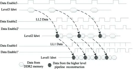
Fig.12 The time sequence of the 3-level paralleled wavelet reconstruction
3 Test results
The Altera Company’s Stratix III EP3SE80 series FPGA platform is chosen in order to test the effectiveness and real-time performance of the proposed de-noising system. In this experiment platform, the input video sources are used from DVI signals with 3 different formats: 1920×1080 at 60Hz, 1280×1024 at 60Hz, and 1024×768 at 60Hz. After acquisition and de-noising process, the 3 video signal outputs are 1920×1080 at 60Hz DVI signals for display.
Afterwards, Quartus 13.1 is used to compile and synthesize the design codes. The synthesis report is presented in Table 2. As shown in Table 2, the system meets the resource requirements, and the highest operating frequency reaches 178MHz (which is higher than the minimum frequency of 148.5MHz required for 1080p60 HD-video).

Table 2 System synthesis report
For actual video applications in video surveillance, the proposed system is able to stably output clear images, and realize dynamic real-time HD-video de-noising.
4 Conclusion
A hardware implementation for real-time HD-video de-noising based on an FPGA from the Altera Company’s Stratix III EP3SE80 series device is presented. The system utilizes a 5/3 lifting wavelet de-noising technique and supports frame rate conversion for HD-video, and a frame rate conversion structure, a 3-level paralleled and pipeline structure, a 1-D folding and pipeline structure, and adaptive threshold filtering. Moreover, the system maintains a balance between low resource consumption and high operational efficiency. The system synthesis results show that the operating frequency is able to reach 178MHz, which meets the minimum frequency requirement of 148.5MHz, allowing for real-time de-noising for 1080p60 HD-videos. Furthermore, the implementation system has been successfully applied to an agricultural surveillance system, and meets not only the needs of a variety of input signal sources but also better deals with noise caused by the front-end of the video surveillance.
[ 1] Shirvaikar M, Bushnaq T. A Comparison between DSP and FPGA platforms for real-time imaging applications. http://spie.org/: SPIE-IS&T, 2009, 7244:724406-1-724406-10
[ 2] Katona M, Pizurica A, Teslic N, et al. A real-time wavelet-domain video de-noising implementation in FPGA.EurasipJournalonEmbeddedSystems, 2006. 1-12
[ 3] Ma X Q. The study and design of real time image collection and de-noising system based on FPGA: [M.S dissertation]. Changchun: College of Communication Engineering, Jilin University, 2006. 26-41
[ 4] Ji Y S, Guo C Z, Fan L L, et al. Real time image processing method of wavelet based on FPGA.Laser&Infrared, 2009, 39(10): 1112-1114
[ 5] Ning Y H, Guo Y F, Ma T B, et al. Architecture design of 5/3 lifting wavelet in FPGA with dynamic RAMs and its applications.ChineseJournalofLiquidCrystalsandDisplays, 2013, 28(6): 927-932
[ 6] Tang Y, Cao J Z, Liu B, et al. FPGA design of wavelet transform in spatial aircraft image compression.ComputerScience, 2010, 37(9): 261-263
[ 7] Guo J, Wu C K, Li Y S, et al. High-performance and low-memory architecture of wavelet transform for JPEG2000.JournalofSouthChinaUniversityofTechnology(NaturalScienceEdition), 2009, 37(5): 38-42
[ 8] Wang K Y, Liu K, Guo J, et al. A line-based, real-time VLSI architecture for 2D lifting integer-to-integer wavelet transform.JournalofCircuitsandSystems, 2010, 15(2): 122-127 (In Chinese)
[ 9] Wang J X, Zhu E. A high-throughput VLSI design for JPEG2000 9 /7 discrete wavelet transform.JournalofSoutheastUniversity(EnglishEdition) , 2015, 31(1): 19-24
[10] Liao H Y. Efficient architectures for 1-D and 2-D lifting-based wavelet transform.IEEETransactionsonSignalProcessing, 2004, 52(5): 1315-1326
[11] Wu B F, Lin C F. A high-performance and memory-efficient pipeline architectures for the 5/3 and 9/7 discrete wavelet transform of JPEG2000 codec.IEEETransCircuitsSystVideoTechnology, 2005, 15(12): 1615-1628
[12] Shi G M, Liu W F, Zhang L, Li F. An efficient folded architecture for lifting-based discrete wavelet transform.IEEETransactionsonCircuitsandSystemsII:ExpressBriefs, 2009, 56(4): 290-294
[13] Wu Z G. Pipelined architecture for FPGA implementation of lifting-based DWT. In: Proceedings of the International Conference on Electric Information and Control Engineering, Wuhan, China, 2011. 1535-1538
[14] Chen Z L, Jin L X, Tao H J, et al. Optimization algorithm of 5/3 lifting wavelet based on FPGA.VideoEngineering, 2015, 39(11): 113-116
[15] Todkar S, Shastry P V S. Flipping based high performance pipelined VLSI architecture for 2-D discrete wavelet transform. In: Proceedings of the 2015 International Conference on Applied and Theoretical Computing and Communication Technology, Karnataka, India, 2015. 832-836
[16] Wen L H, Xie J, Wang G X. Design and implementation for 2-D IWT using parallel computing units.Microelectronics&Computer, 2013, 30(7): 47-50
[17] Daubechies I, Sweldens W. Factoring wavelet transforms into lifting steps.JournalofFourierAnalysis&Applications, 1998, 4(3): 247-269
[18] Chang S G, Yu B, Vetterli M. Adaptive wavelet thresholding for image de-noising and compression.IEEETransactionsonImageProcessing, 2000, 9(9): 1532-1546
[19] Moulin P, Liu J. Analysis of multi-resolution image de-noising schemes using generalized Gaussian and complexity Priors.IEEETransactionsInformationTheory, 1999, 45(3): 909-919
[20] Zhong Y D. A design of the core module of high-speed satellite image decoding system based on wavelet transform: [M.S degree dissertation]. Xi’an: School of Mechanic-Electronic Engineering, Xidian University, 2009. 23-27
10.3772/j.issn.1006-6748.2017.02.014
①Supported by the Spark Program of China (No. 2013GA780007) ,and Key Scientific Research Project of Guandong Agriculture Industry Business Polytechnic(No. xyzd1604).
②To whom correspondence should be addressed. E-mail: qjhuang@gdaib.edu.cn
on Apr. 22, 2016
ojie, born in 1981. She received her B.S. and M.S. degrees from South China University of Technology in 2005 and 2008 respectively. Her research interests include digital image processing and computer communications.
杂志排行
High Technology Letters的其它文章
- Mining potential social relationship with active learning in LBSN①
- Negation scope detection with a conditional random field model①
- A case study of 3D RTM-TTI algorithm on multicore and many-core platforms①
- Closed-form interference alignment with heterogeneous degrees of freedom①
- A transition method based on Bezier curve for trajectory planning in cartesian space①
- Semantic image annotation based on GMM and random walk model①
