Validation of CFD Simulation for Ship Roll Damping
2017-05-13BUShuxiaQIUGengyaoGUMinWUChengshengZENGKe
BU Shu-xia,QIU Geng-yao,GU Min,WU Cheng-sheng,ZENG Ke
(China Ship Scientific Research Center,Wuxi 214082,China)
Validation of CFD Simulation for Ship Roll Damping
BU Shu-xia,QIU Geng-yao,GU Min,WU Cheng-sheng,ZENG Ke
(China Ship Scientific Research Center,Wuxi 214082,China)
Ship roll damping is a key factor for predicting large amplitude roll motions,such as parametric roll and stability under dead ship condition.In this paper,the free roll motions of an international standard model ship 2792 for dead ship are simulated based on the unsteady RANS equation in calm water by two types of meshes,the sliding mesh and the overset mesh.The free roll decay curves of numerical simulations are compared with experimental results,and the roll damping coefficients are also compared with that in Ikeda’s simplified formula.The calculated free decay curves agree quite well with the free decay curves from the experiments,and the errors of roll damping coefficient calculated by CFD are smaller than that from Ikeda’s simplified formula,which validate that the unsteady RANS equation can be used to predict roll damping.
Roll damping;RANS;free rolling;overset mesh;sliding mesh
0 Introduction
The large roll motions such as parametric roll and dead ship stability are one of critical risks for the safety when the ship sails in the sea,and the roll damping is essential to accurately predict these large roll motions.However,the accurate prediction of ship roll damping is very difficult,except for high cost experiments.Therefore,a numerical method for the prediction of large roll damping with high accuracy is desirable.
In general,most of the calculation methods are based on the potential theory,and the most common method is Ikeda’s method[1-5].These formulas can be used quite well for the conventional ships,but the prediction results are sometimes conservative or underestimated for the unconventional ships[6-8].This is because the large roll damping is strongly nonlinear,which has relationships with fluid viscosity and flow characteristics,such as the flow separation and vortex shedding.So the empirical or semi-empirical formulas can not take the full consideration of different characteristics for different objects.Currently,the vulnerability criteria for parametric roll and dead ship stability are under development by International Maritime Organization(IMO)at second generation intact stability criteria,in which the roll damping coefficientswere proposed by using Ikeda’s simplified method.The calculated results of most traditional ships by Ikeda’s simplified method can fit experimental data quite well at the same order magnitude.However,if the size is outside the application range of Ikeda’s method,or for the large amplitude motions in some phenomena,the accuracy will be low,which limits the application scope of Ikeda’s method.
In addition to Ikeda’s simplified method,the Correspondence Group on Intact Stability regarding second generation intact stability criteria also proposed that the roll damping could be calculated by roll decay/forced roll test or CFD simulation[9].Although the model tests can predict the roll damping very well,but it is costly and time-consuming and most of experimental data are limited to a certain frequency range and particular geometry,which is impossible for the large-scale expansion of the application[10-11].
For the accurate calculation of roll damping,the influence of viscosity must be considered. The CFD numerical simulation can consider different objects and its characteristic,so it can be used to predict roll damping.Forced roll method and free roll decay method are two main methods for the calculation of the roll damping.
In our previous studies[12],the forced roll motions of one 2D ship section based on the methods of orthogonal design and variance analysis were carried out,in which different calculation parameters for the roll damping are analyzed,and the free motions of one 3D containership were also carried out.
The aim of this paper is to study the feasibility of CFD code for the prediction of the roll damping.The roll damping of one standard model 2792 which is an international standard model for dead ship stability is simulated based on the unsteady RANS equation in calm water by CFD code,and two methods for grid system are used during numerical simulations,one is sliding interface method and the other is dynamic overset grid method.
In the sliding mesh technique,two mesh zones are used,and they are contacted by a‘mesh interface.’The inner zone which is close to the bodies is moving with bodies,and the outer zone translates with bodies,which leads to the relative rotation between the outer zone and the inner zone.Overset meshes,also known as overlapping meshes,are used to discretize a computational domain with several different meshes that overlap each other in an arbitrary manner.Overset mesh has a background region enclosing the entire solution domain and one or more smaller regions containing the bodies within the domain.Both methods are most useful in problems dealing with moving bodies.
In this paper,the free decay curves as well as the roll damping coefficients calculated by both methods are compared with experimental results.Considering that the Ikeda’s simplified method is recommend for the evaluation of roll damping coefficients in the latest drafts for parametric roll at second generation intact stability[13],the results of roll damping coefficients are also compared with that from Ikeda’s simplified formula.
1 Ship geometry and experiment
The international standard model ship 2792 for dead ship stability with scale of 65.0 is adopted for the CFD computations.Main particulars of the standard model 2792 are given in Tab.1 and the body plans are shown in Fig.1.
Typical models used to study roll decay are usually with bilge keels which take account of the contribution of bilge keels to roll damping. However,for simplicity,models without bilge keels in calm water were used in this paper. The free roll decay experiments for the ship 2792 are carried out at the towing tank of Wuhan University of Technology,as shown in Fig.1. The roll decay curves were measured by a MEMS(Micro Electro-Mechanical System)-based gyroscope placed on the ship model,and the initial roll angles are 10°,20°and 25°,respectively.

Tab.1 Principal particulars of the 2792 model

Fig.1 The ship 2792(Left:lines;Right:ship model in free roll decay test)
2 Computation method
2.1 Mathematical model and numerical method
All computations are performed by solving unsteady RANS equation.RNG k-ε two-equation turbulence model is employed for the enclosure of the governing equations.The VOF method is adopted for the treatment of nonlinear free surface.The pressure-correction algorithm of SIMPLE type is used for the pressure-velocity coupling.Two methods are used during simulations,one method is the sliding mesh,and the other is the overset mesh.The enhanced wall function is adopted based on the previous studies[12].
In simulations,the modes of roll,sway and heave are free and other modes are constrained. The type of body mesh and hull geometry are shown in Fig.2,and the solution domains are shown in Fig.3 and Fig.4,respectively.The boundary of the computational domain is composed of inlet boundary,outlet boundary,wall boundary(hull surface),and outer boundary.

Fig.2 The hull meshes and geometry of the ship 2792

Fig.3 Computational domains and meshes in the method of sliding mesh
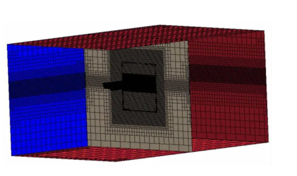
Fig.4 Computational domains and meshes in the method of overset mesh
2.2 Analysis methods
According to the latest drafts for the vulnerability criteria of parametric roll(Correspondence Group on Intact Stability,2015),if we introduce the equivalent linear damping coefficient B44φa(),the roll motion in calm water can be modelled as:

where Ixx+Jxxis virtual moment of inertia in roll,W is ship weight,GM is initial metacentric height.Then:

In Ikeda’s simplified formula,B44is normalized as follows:

where B is ship breadth,▽is ship displacement volume and ρ is water density.
In order to compare the results of roll damping coefficients between CFD and the Ikeda’s simplified method,the extinction curve should be expressed as the linear formula(4),which is the essential component of the roll damping.

where Δφ is decrement of roll decay curve and φmis mean swing angle of roll decay curve.
The linear fitting coefficient A can also be calculated as formula(5),for the conservation of energy.
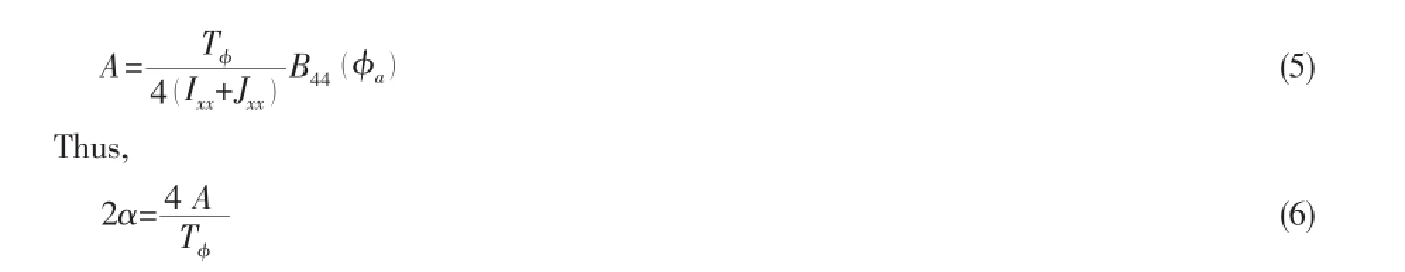
The results of 2α are compared for different methods,which can analyze the combined error of roll amplitude and roll period.The natural roll periods measured in model tests are used in the Ikeda’s simplified formula,taking into consideration that only the equivalent roll damping coefficient can be calculated by Ikeda’s simplified formula.
3 The calculation results and analysis
3.1 The grid analysis
A simple grid analysis is given out for the dynamic overset grid method.The profile of the computational domain is shown in Fig.5.This computational domain is separated into two main regions,background region and overset region,and each region is further divided into several small zones.The mesh in overlap region is refined to guarantee the data exchange between overset region and background region.The waterline plane region is also refined to capture the free surface.
Generally,the size for the background region and the overset region should be large enough to simulate actual situation.However, the size of the overset region should be as small as possible to reduce computation cost in the actual simulations.In this paper,two different widths of overset region are analyzed,one is 4B(S1)and another is 5B(S2).This is because the width is the main influential size when simulating free roll motion in calm water.The comparison results shown in Fig.6 show that the two curves are almost the same,which means that the width 4B is enough for the simulations.
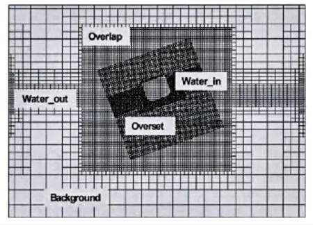
Fig.5 The profile of computational domain for the overset grid method
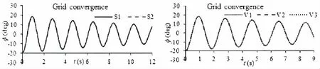
Fig.6 Comparison results(Left:different widths of overset region;Right:different base sizes)
Three cases for the grid convergence are also carried out to confirm the base size.In the first case shown as V1 in Fig.6,the base size for the background domain is equal to 0.08 m and the base size for the overset domain is equal to 0.04 m.In the second case shown as V2, the base size is decreased to 0.07 m for the background domain and 0.035 m for the overset domain.In the third case shown as V3,the base size is kept for the background domain and the base size for the overset domain is decreased to 0.03 m.The results show that the base size in the first case is small enough for the numerical simulations.
3.2 The results of standard model 2792
For the free roll decay motions of the ship model 2792,the initial roll angles 10°,20° and 25°are simulated respectively by two methods,as shown from Fig.7 to Fig.9,and the results of coefficient 2α are shown in Tab.2.
The curves show that the periods and amplitudes calculated by the overset gird method agree better with the experimental data than that by the sliding mesh method.The results of roll damping coefficient 2α show that the accuracy of CFD code is higher than Ikeda’s simplified formula.

Fig.7 Free decay curve for 2792-initial heel 10°(Left:overset mesh;Right:sliding mesh)

Fig.8 Free decay curve for 2792-initial heel 20°(Left:overset mesh;Right:sliding mesh)

Fig.9 Free decay curve for 2792-initial heel 25°(Left:overset mesh;Right:sliding mesh)
During simulations,we found that the heave motion simulated by the sliding mesh method fluctuated remarkably when compared the results with that simulated by the overset mesh method,although the roll amplitudes almost the same,as shown in Fig.10.This is mainly be-cause the interface data exchange for sliding mesh is not smoothness between static and motion regions.
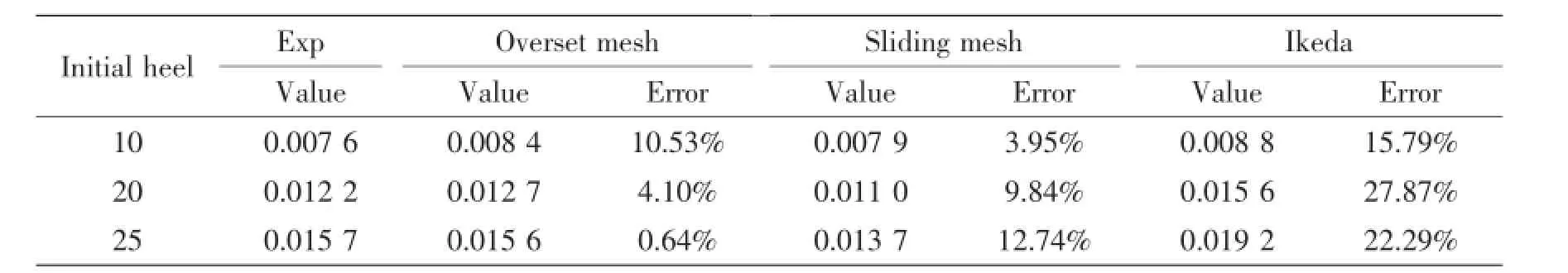
Tab.2 Results of 2α calculated by different methods for the ship 2792
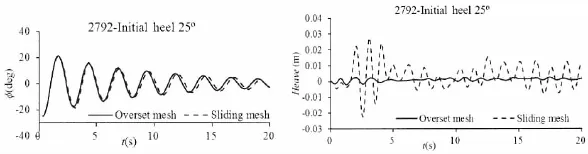
Fig.10 Comparisons of free roll decay curve and heave curve between overset mesh and sliding mesh
4 Conclusions
As the comparisons for the free rolling motions of one standard model among two methods of numerical simulations,Ikeda’s simplified method and experiments,the following remarks are noted:
(1)The free rolling based on unsteady RANS equations has the ability to predict the roll damping,at least for large roll amplitudes.
(2)For the method of dynamic overset grid,the natural roll periods agree quite well with experimental results,but the roll amplitudes are slightly larger than experimental results.For the method of sliding interface grid,both the natural roll period and the roll amplitude are slightly larger than experimental results.
(3)The roll damping coefficients calculated by CFD are better than that calculated by Ikeda’s simplified formula,which indicates that the free rolling based on unsteady RANS equation has the ability to predict the roll damping,at least for large roll amplitudes.
(4)Based on current studies,the following combination of calculation parameters is recommend when simulating free roll decay motion,unsteady RANS equations combined with RNG k-ε two-equation turbulent model to solve flow field,VOF method to capture free surface,sliding interface technique or dynamic overset mesh technique to compute bodies motions,enhanced wall function to treat near-wall boundary layer.
The bilge keels were not considered in our simulations.However,the bilge keel damping contributes a large portion to the total damping[14],so more works should be carried out in fu-ture to validate the feasibility of CFD for roll damping,and to improve the accuracy,especially for the unconventional ship with bilge keels.
Acknowledgements
The model tests for ship 2792 were conducted in Wuhan University of Technology,and the experimental data were provided by Prof.Mao Xiaofei from Wuhan University of Technology and Dr.Lu Jiang from China Ship Scientific Research Center.The research is supported by Ministry of Industry and Information Technology of China(No.[2016]26).The authors sincerely thank the above organization and individuals.
[1]Ikeda Y,Himeno Y,Tanaka N.On eddy making component of roll damping force on naked hull[J].Journal of the Society of Naval Architects of Japan,1977a,162:59-69.
[2]Ikeda Y,Komatsu K,Himeno Y,Tanaka N.On roll damping force of ship-effect of hull surface pressure created by bilge keels[J].Journal of the Society of Naval Architects of Japan,1977b,165:31-40.
[3]Ikeda Y,Himeno Y,Tanaka N.Components of roll damping of ship at forward speed[J].Journal of the Society of Naval Architects of Japan,1978,143:113-125.
[4]Ikeda Y,Katayama T.Roll damping prediction method for a high-speed planning craft[J].Proceedings of the 7th International Conference of Ships and Ocean Vehicles(STAB’2000),2000,2:532-541.
[5]Ikeda Y.Prediction methods of roll damping of ships and their application to determine optimum stabilization devices[J]. Marine Technology,2004,41(2):89-93.
[6]Japan.Interim verification and validation report on simplified roll damping[R].IMO SLF 54/INF 12,Annex 7,2011a.
[7]Japan.Additional validation data on simplified roll damping estimation for vulnerability criteria on parametric rolling[R]. IMO SLF 54/INF 12,Annex 11,2011b.
[8]Sweden.Evaluation of Ikeda’s simplified method for prediction of roll damping[R].IMO SLF 54/3/6,2011.
[9]United States&Japan.Draft guidelines of direct stability assessment procedures as a part of the second generation intact stability criteria[R].IMO SDC1/INF.8,Annex 27,2014.
[10]Bass D W,Haddara,M R.Non-linear models of ship roll damping[J].International Shipbuilding Progress,1988,35(401):5-24.
[11]Blok J J,Aalbers A B.Roll damping due to lift effects on high speed monohulls[C].FAST`91,1991,2:1331-1349.
[12]Gu Min,Lu Jiang,Bu Shuxia,Wu Chengsheng,QiuGengyao.Numerical simulation of the ship roll damping[C]//12th STAB,Glasgow UK,2015:341-348.
[13]ISCG(the Correspondence Group on Intact Stability).Draft explanatory notes on the vulnerability of ships to the parametric roll stability failure mode[R].IMOSDC3/INF.10,Annex 17,2015.
[14]Bassler C C,Reed A M.An analysis of the bilge keel roll damping component model[C]//10th STAB.St.Petersburg, Russia,2009:369-386.
摘要:船舶横摇阻尼是影响参数横摇和瘫船稳性等大幅横摇运动的关键参数。文中基于非定常RANS方程在静水中对模型2792进行了自由横摇衰减的数值模拟,该模型是船舶第二代完整稳性衡准制定中瘫船稳性研究的国际标准船模,数值模拟中采用了两种网格类型,一种是滑移网格,另一种重叠网格。计算结果表明,数值模拟的自由横摇衰减曲线和模型试验结果吻合良好,另外CFD计算的横摇阻尼与试验值的误差小于Ikeda’s经验公式计算的误差,证明非定常RANS方程可用于预报横摇阻尼。
船舶横摇阻尼的CFD数值模拟研究
卜淑霞,邱耿耀,顾民,吴乘胜,曾柯
(中国船舶科学研究中心,江苏无锡214082)
横摇阻尼;RANS;自由横摇衰减;重叠网格;滑移网格
U661.32+1
:A
卜淑霞(1989-),女,中国船舶科学研究中心博士研究生,工程师;
1007-7294(2017)03-0275-09
U661.32+1
:A
10.3969/j.issn.1007-7294.2017.03.003
邱耿耀(1985-),男,中国船舶科学研究中心高级工程师;
顾民(1962-),男,中国船舶科学研究中心研究员,博士生导师;
吴乘胜(1976-),男,中国船舶科学研究中心研究员;
曾柯(1989-),男,中国船舶科学研究中心助理工程师。
Received date:2016-12-29
Foundation item:Supported by Ministry of Industry and Information Technology of China(No.[2016]26)
Biography:BU Shu-xia(1989-),female,Ph.D.Candidate,E-mail:bushuxia702@126.com;
QIU Geng-yao(1985-),male,engineer;
Gu Min(1962-),male,researcher.
猜你喜欢
杂志排行

船舶力学的其它文章
- Numerical Study on the Nonlinear Characteristics of Longitudinal Motions and Wave Loads for SWATH Ship in Regular Head Waves
- Coupled Hydrodynamic and Aerodynamic Response Analysis of a Tension-Leg Platform Floating Wind Turbine
- Motion Behavior of a Semisubmersible in Freak Waves
- Numerical Investigation of the Side Wall Effects for Two Ship Models Advancing Parallel in Waves
- Three-Dimensional Problem of the Compressible Water-gas Mixture Impacting on Rigid Plates
- Three Dimensional Crack Path Prediction of Brittle Fracture in Weldment Under Fatigue Load