Multi-Gradient Routing Protocol for Wireless Sensor Networks
2017-05-09YingQiuShiningLiZhigangLiYuZhangZheYang
Ying Qiu, Shining Li, Zhigang Li, Yu Zhang, Zhe Yang
School of Computer, Northwestern Polytechnical University, Xi’an 710072, China
I. INTRODUCTION
In recent years, wireless sensor networks are applied to more and more fields with different needs, rather than simply gathering sensor data. In home or building automation fields,sensor nodes are often required to interact with Internet-based devices directly, such as controlling a light switch or get the readings of a specific smoke sensor. IPv6 sensor networks gracefully solve these interactive challenges by adopting light-weight IPv6 implements to sensor nodes[1]. Since IPv6 is proved suitable for low-power and resource-constrained devices[2][3], the ability of end-to-end IP networking releases the full power of the sensor networks, each node has at least one global IPv6 address that can be reached from anywhere that Internet is available.
It is a challenging work to support IPv6 in sensor networks with restricted computation ability and extreme small memory devices.First, the primary traffic pattern in IPv6 networks is the end-to-end traffic. Each node should have the ability to communicate with any other nodes in the network with as few hops as possible. Second, multiple sinks may exist on network edges to act as gateways to Internet, or redundant sinks to prevent single node failure. Each node should have the ability to effectively route packets to these sinks including data collection tasks. Third, wireless communication is an energy-expensive operation that dominates the lifetime of the battery-powered sensor networks. The routing protocol must take energy-efficiency into consideration. The former two challenges are quite different from traditional one-to-many and many-to-one traffic patterns that are heavily studied by sensor networks academy.
Some efforts are made in recent years to solve end-to-end packet routing in sensor networks. RPL[4] constructs a destination oriented DAG (Directed Acyclic Graph) to route upward and downward packets. LWB[5]utilizes Glossy[6] as the underlying flooding mechanism and turns a whole network to a logically shared bus to support any traffic, just like Ethernet does. ORPL[7] improves RPL with opportunistic routing to reduce end-toend delay and constructs an routing set with bloom filter to reduce end-to-end packet transmission hops.
In this paper, the authors present a multi-gradient routing protocol called MGRP for wireless sensor networks. MGRP uses a simple and efficient gradient constructor substitutes traditional link estimator, which is responsive to network dynamics.
In the paper, we present MGRP, a multiple-gradient routing protocol to tackle the challenges raised by IPv6-based sensor network. We make the following contributions:
1. We propose a fully distributed general-purpose routing protocol, which supports endto-end, one-to-many and many-to-one traffic, and more efficient than the state of the art routing protocol in end-to-end traffic.
2. We combine neighbor link estimation and routing information in MGRP which reduces packet exchange and memory size for the neighbor table while still remains robust to network dynamics and node failures.
3. We evaluate MGRP on real world testbeds,the result indicates that MGRP’s end-to-end delay is significantly lower than RPL with the same experimental settings.
II. RELATED WORKS
Routing in battery-powered wireless sensor networks is an active research topic in literature over the past years. CTP[8] presents a tree routing protocol that computes anycast routes to one or multiple sinks by adopting data-path validation and adaptive beacons. It builds a routing tree with the sink as the root and routes packets upwards the tree to the sink with best efforts. Since CTP only builds an upwards path to the sink, which is suitable for many-to-one data collection tasks, it can’t effectively deal with end-to-end scenarios.
RPL[4] is a distance-vector routing protocol for IPv6 sensor networks, defined under the specification proposed by IETF ROLL Working Group. Instead of building a full mesh, RPL constructs a Destination-Oriented Directed Acyclic Graph (DODAG) to forward packets both upwards and downwards to provide the end-to-end routing. Packets are first routed upwards to a common ancestor of the source and destination nodes, and then forwarded downwards to the destination. Each packet must be routed in this way, even there exists a shorter path. RPL’s routing strategy increases hop count and packet delay between source and destination nodes.
LWB[5] is a rather different routing protocol that supports diverse traffic patterns,including one-to-many, many-to-one and many-to-many traffic. LWB turns a multi-hop low-power wireless network into an infrastructure similar to a shared bus by mapping all traffic demands on fast network floods provided by Glossy[6]. All nodes in LWB are potential receivers of all data. LWB globally schedules every flood with a centralized scheduler. Floods with Glossy make LWB resilient to network dynamics, node failure and interference.
ORW[9] presents an opportunistic routing scheme for low-power-listening duty-cycled networks. A packet is forwarded to the first awoken node that successfully receives it and offers routing progress. ORW presents a new anycast routing metric called EDC to reflect the multi-path routing nature, which integrates duty-cycled nodes and relies on energy and delay as the key routing metrics.
ORPL[7] adds opportunistic routing to RPL, aiming for low-latency, reliable communication in duty-cycled networks, and focus on providing a low-power mesh that supports end-to-end traffic with arbitrary patterns.ORPL uses anycast over a low-power-listening MAC in order to support opportunistic routing. A packet is forwarded to the first awake neighbor node that satisfies routing requirements to reduce latency. ORPL uses routing set to make downwards forwarding decision. The routing set can be represented as a bloom filter to reduce memory requirements.OPRL has the same problem as RPL does,that packets should first be forwarded upwards then downwards, even there is a shorter path.MGRP solves this by constructing a full gradient vector, which always chooses the shortest path if exists.
MGRP’s design is inspired by prior works on gradient construction, link estimation and routing selection. MGRP uses a different link estimation strategy to reduce memory requirements and adopts similar routing scheme just as ORPL does, but MGRP will always choose the shortest path and improves latency in endto-end traffic.
III. MGRP DESIGN
This section presents MGRP, which utilizes gradient routing to handle multiple traffic patterns. We will describe MGRP’s building components in detail, including (1) Network assumptions; (2) Gradient construction, the dynamic process of gradient calculation on network initialization stage; (3) Routing packets with gradient vectors.
3.1 Network assumptions
MGRP has several assumptions on the target sensor networks, including assumptions on MAC layer and node ID. The MAC layer should support broadcast, unicast, anycast and low-power-listening. The most commonly used MAC protocols based on IEEE 802.15.4[10] support broadcast, unicast and low-power-listening. Anycast is required for opportunistic routing. It is supported by several MACs such as A-MAC[11] and Any-MAC[12].
MGRP has a special assumption on node ID. Suppose there are n nodes in the network,each node should have a unique ID numbered from 0 to n-1 without redundancy. This ensures gradient vector can be represented as an array start from index 0, which is convenient for implementation. If node ID is not numbered in that way, protocol implementer should add an extra mapping table to map actual node IDs to continuous numbers.
3.2 Gradient construction
Gradient is the routing metric of MGRP. In general, packets are forwarded downwards to nodes with lower gradient. In MGRP, each node maintains a gradient vector recording its gradients to other nodes in the network. For example, Figure 1 shows a 4-node network with the assumption that the difference of gradient of each pair is already known. Values in parentheses are the gradients to root nodes which are figured out by Bellman-Ford shortest-path algorithm. The right part of Figure 1 shows the calculated gradient vectors of each node, which stores the gradients to other nodes.
There are two special cases of the gradient value. One is the gradient to itself, which is always 0, represents the lowest position. It’s convenient for routing engine to stop finding the next hop and signaling an event of packet reception when gradient of zero is reached.The other special case is the undefined gradient, it is set to the maximum that the gradient vector element can represent, e.g., if we use 1 byte to represent the gradient, thus the undefined gradient is 255. It is required for the gradient construction algorithm presented in the following section to work properly.
Gradient vectors are exchanged between neighbor nodes. Each node periodically broadcast its gradient vector to the neighbors. Once neighbor’s gradient vector is received, the receiver will update its own gradient vector with the minimum gradient calculated. The progress of gradient propagation is illustrated in Figure 2.
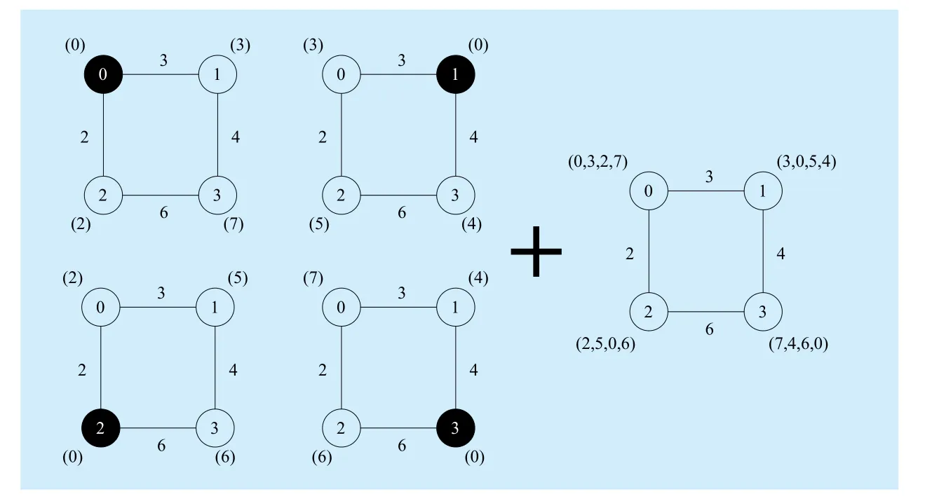
Fig. 1 An example illustrates gradient vectors for a 4-node network. Black nodes represent root nodes, values in parentheses are the gradients to root; values between two nodes are the differences of gradient of node pairs
At the very beginning, gradient to other nodes is an undefined gradient represented asin Figure 2. After the first round of routing information exchanging, gradient to the onehop neighbor is known. Gradients to all other nodes will be discovered in O(n) rounds,where n is the number of nodes in the network. The computation complexity is similar to distributed Bellman-ford algorithm, the cost values of nodes are updated in parallel.
The challenge of gradient construction is that the gradient between two nodes as Figure 2 shows can’t easily be figured out. It is not a constant since the wireless channels are usually interfered by environmental factors, such as WIFI or other noises. MGRP exploits a novel approach different from traditional link estimators such as ETX[8], 4Bitle[13], EDC[9],which is inspired by TCP’s Slow-start/AIMD algorithm[14]. MGRP integrates gradient construction into the process of routing information propagation. When receiving routing information, MGRP update gradient vector according to Eqn.1 base on the fact that node’s gradient to root is close to its neighbor’s.

GVr,irepresents receiver’s ith element in a gradient vector, which is the gradient to node i. GVt,iis the sender’s ith element in gradient vector. COST is the cost for one hop transmission. The choice of COST is closely related to the maximum hop limit and the max gradient as Eqn. 2 shows.

As an example, suppose gradient is represented with 1 byte, i.e. Gradientmaxis 255,COST is 32 per hop and Hopmaxis 7. In this case, target network won’t exceed 7 hops.MGRP user must decide the number of maximum network hops in advance to calculate the value of COST.
Since link quality is not a constant, MGRP maintains a periodic aging timer with interval T to push nodes with poor link quality to a higher gradient. Once the aging timer fires,each item in the gradient vector is increased by 1. Together with the gradient update strategy described in Eqn.1, this makes the gradient construction a dynamic continuous progress just like TCP’s congestion avoidance algorithm does. When the link quality to the neighbor is good, the node’s gradient will quickly converge to neighbor’s gradient. When the link is poor, node’s gradient will gradually increase to a reasonable value. The combination of these two processes results in dynamically maintained gradient vectors for the nodes.
Figure 3 shows an example of the new gradient update strategy. Each matrix is a collection of gradient vectors of the whole network at a specific round. After 11 rounds of routing information exchanging, the gradient matrix finally converges. Values in gradient matrix reflect the hop count to other nodes. Take round 11 as an example, the value of position (0, 3)is 68, means node 0 to node 3 has 2 hops. The time during for convergence is bounded by network diameter d, which is the number of maximum hops between two edge nodes.

Fig. 2 An Example of gradient construction for a 4-node network
3.3 Routing with gradient vector
MGRP is designed to support multiple traffic patterns, including end-to-end, one-to-many and many-to-one traffic. Packet routing in MGRP is based on the gradient that is constructed as the previous section describes.Gradient-based routing is more flexible than parent-based routing strategy, the primary principle is packets are forwarded from high gradient to low, each forward operation pushes the packet closer to the destination.
One-to-many traffic is usually used for disseminating commands to the entire network. The trivial idea is flooding packet with broadcasts. Each node broadcasts the packet it receives to propagate the packets over the network. But this will lead to serious redundancy,collision and contention that well known as the broadcast storm, which consumes a huge amount of energy. In MGRP, since the gradient vector is constructed, broadcast is only forwarded to the lower gradient, which effectively suppresses redundant broadcasts.
End-to-end traffic is the primary traffic pattern in IPv6 packet transmissions. Many-toone traffic is equal to end-to-end traffic which each packet has the same destination, so we’ll focus on end-to-end traffic routing in the following text.
There are two types of end-to-end routing with different MAC layers. If MAC layers only support unicast, MGRP routing has to use unicast to forward packets. When MAC layer supports anycast, MGRP can take advantage of opportunistic routing to reduce packet delay.
3.3.1 Unicast routing
In unicast routing, packets are forwarded to neighbor nodes with the minimum gradient.As Figure 4 shows, node 4 has a packet to send to node 0. Once the gradient to node 0 is calculated, node 4 has 3 choices (neighbor nodes 1,2,3, with gradient less than node 4).MGRP will choose node 1 as the next hop since its gradient is the minimum among node 4’s neighbors.
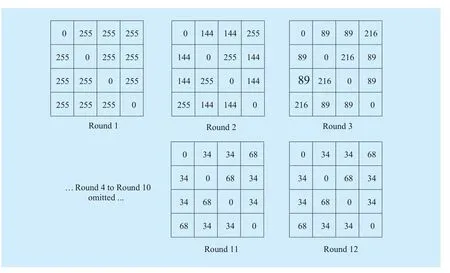
Fig. 3 Example of MGRP’s gradient update strategy
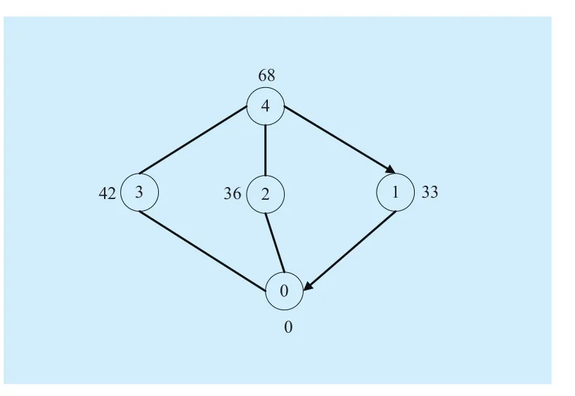
Fig. 4 Example of unicast routing

Algorithm 1 Parent table maintenance algorithm
The challenge is that sender must decide the destination before transmission, which is not easily inferred from the gradient vector.Thus, a sender should record extra information about which neighbor is the suitable next hop for a certain destination. MGRP maintains an extra table to store parent information. On receiving neighbor’s gradient vector, MGRP finds out the neighbor with minimum gradient,and records that neighbor to the parent table.This algorithm is described in Algorithm 1.
Retransmission is required when packet is not ACKed by the receiver. MGRP set a threshold for the maximum number of packet retransmission. Reaching the packet retransmission threshold implies the link to the parent is not reliable. MGRP will try to change parent immediately to find a reliable path to the destination. The detail will be described in section 3.3.4.
3.3.2 Anycast routing
Sensor networks often adopt Duty-cycled/Low-power-listening MAC to reserve energy.Node’s radio is turned off in most times, it turn on its radio for a very short period to detect transmission requests. In such case, anycast is better than unicast on packet delay. Packets can be forwarded to the neighbor nodes that first wake up and ACK to the transmission request.
Different from unicast routing, the decision of anycast routing is made on the receiver side. The decision of forwarding not only require lower gradient, but also should take the difference of gradient into consideration to reduce hop count to the destination. The receiver makes the routing decision according to Eqn.3, make sure that each time a packet is forwarded will descend nearly one hop.

Figure 5 shows an example of anycast routing. Each node is in the low-power-listening state. Node 5 sends a packet to node 0, node 4 wakes up first and receives the packet from node 5. But node 4’s gradient doesn’t satisfy the inequality in Eqn.3, so node 4 won’t forward the packet and back to sleep. Later, node 3 wakes up and satisfies formula Eqn.3, it will forward this packet even its gradient is higher than node 2’s.
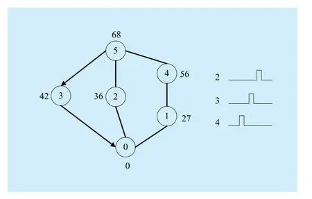
Fig. 5 Example of anycast routing
3.3.3 Timer for broadcast routing information
Routing information should be periodically exchanged to maintain the gradient vectors.The frequency of routing information exchanging is close related to energy consuming.Since nodes in sensor networks seldom move,MGRP adopts an exponential timer to update gradient vectors. At the initializing stage of the network, nodes send routing information frequently. After the gradient vectors converge,routing information is reduced accordingly.
One exception is when MGRP find network dynamic situation occurs, which will immediately reset the timer to the minimum to rebuild gradient vectors quickly.
3.3.4 Network dynamics
Sensor networks are easy to be influenced by wireless interference, node movement and node failure. Gradient vectors should reflect these network dynamics quickly to provide accurate routing metric.
The event of reaching packet retransmission threshold or RSSI value changes greatly can be used to predict the network dynamics. When a node detects network dynamics,the first thing it should do is to reset its own routing information timer as section 3.3.3 described. Then, its neighbors should be notified to update their gradient vectors too. MGRP restricts only neighbors in 2-hop’s range are notified to reduce packet exchanging. In unicast routing, the parent table is cleared in order to find a better next hop.
IV. IMPLEMENTATION
We implement MGRP on TinyOS 2.1.2, consist of a configuration MgrpC and a module MgrpP, with the default BoXMAC-2[15]low-power-listening layer that support broadcast and unicast.
4.1 Routing information representation
Due to IEEE 802.15.4’s restriction, one packet can only deliver 127 Bytes. If each entry of gradient vector takes one Byte, one routing packet can carry about 100 entries. When network scale is larger than 100, more routing packets are necessary. In addition, the duplicate gradient value can often be found in the gradient vectors, especially the undefined gradient value. In order to support large-scale network, MGRP supports two types of routing information packets.
1. implied routing information packets, make use of gradient vector index to represent node ID;
2. explicit routing information packets, node ID is explicitly added before its gradient,it is useful to represent the gradient vector with lots of duplicate values.
4.2 Memory usage
Memory is a restricted resource on sensor nodes. Popular sensor nodes such as TelosB only has 10KB RAM, IRIS has only 8KB RAM. MGRP uses less RAM than RPL, we use 1 byte to store a gradient value, and COST is set to 32 to support at most 7 hops. In our experiment with 42 nodes, the gradient vector is 42 bytes, and a parent table is 42*2=84 bytes, totally 42+84=126 bytes.
V. EVALUATION
In this section, we perform experiments on real-world testbeds to evaluate MGRP’s performance. The result shows MGRP outperforms RPL on end-to-end delay while remains comparable packet delivery ratio. Another thing we have observed is that MGRP responds quickly to network dynamics, including node movement and node failure.
5.1 Experiment setup
We evaluate MGRP on our testbed which consists of 42 NPUMOTE3 sensor nodes. Each node has an Atmega128RFA1 MCU with an IEEE 802.15.4 radio integrated. Nodes were deployed in a 70m x 30m office, with default+3.5dbm transmit power and the default channel is set to 26.
We have measured the packet loss of each pair of nodes as Figure 6 shows. Lighter color means link quality between two nodes is better. Darker color means the link quality is poor. Black grid means there is no link between node pairs. The packet loss matrix is nearly symmetric with respect to the minor diagonal, reflects the fact that most wireless links are symmetric.
5.2 Evaluation of gradient vectorconstruction
The quality of the gradient vector greatly influences the accuracy of packet routing. In this section, we evaluate and prove that the gradient vector is well established.
5.2.1 Gradient vector construction
Figure 7 shows the gradients to node 0 among 1000 rounds. Gradients are proved converge quickly in about 10 rounds. We can find there are clearly 3 levels with gradient around 32,64 and 96, respectively represent 1, 2, 3-hops neighbors. The gradient is not a constant due to packet loss. The maintenance of gradient vector is a dynamic progress.
Figure 8 shows the average gradient matrix among 1000 rounds in the experiment. Nodes on different hops can easily be distinguished.Grids with light yellow represent a 1-hop nodes pair. Orange color grid is a 2-hop node pair. If compare the gradient matrix with packet loss matrix in Figure 6, we can discover that they have the similar pattern of colors, which proves the gradient matrix is well constructed.
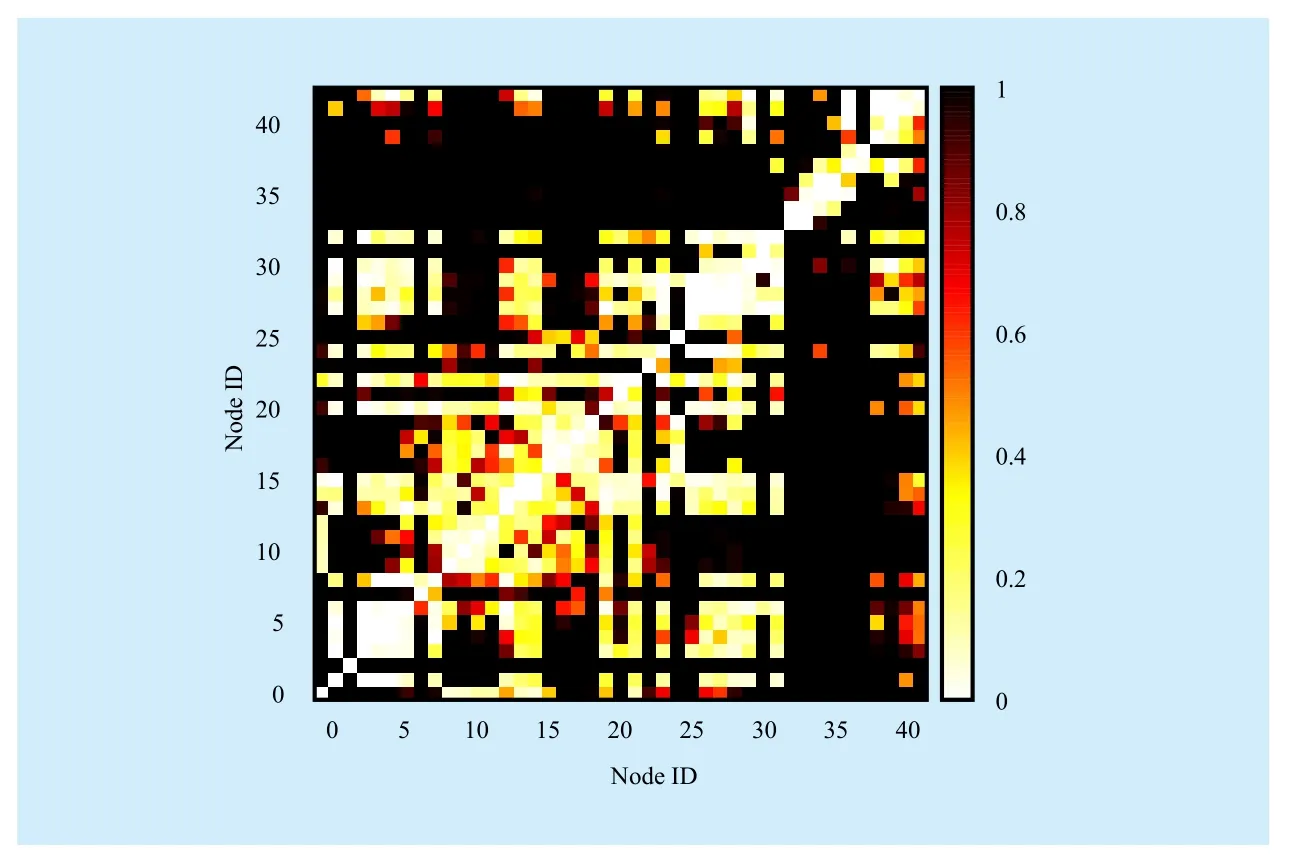
Fig. 6 Average packet loss in experiment settings
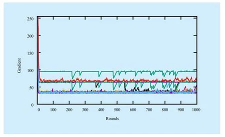
Fig. 7 Gradients to node 0 among 1000 rounds
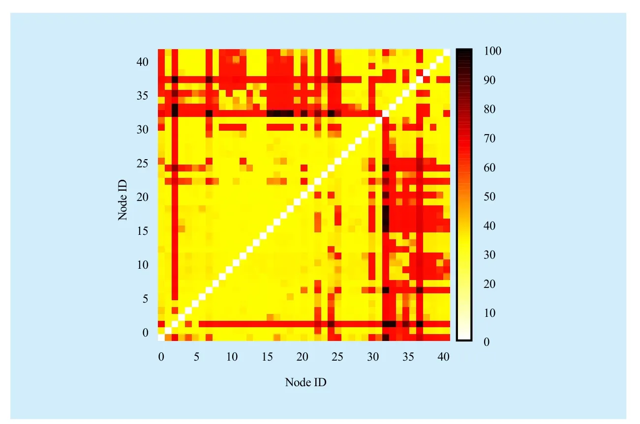
Fig. 8 Average gradient matrix constructed of 42 nodes among 1000 rounds.
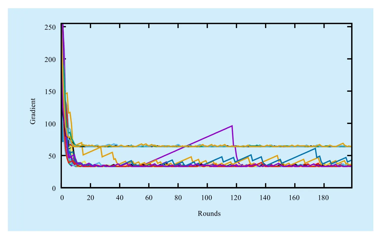
Fig. 9 Response to node outage
5.2.2 Response to node outage
Node outage is a common failure in sensor networks. In this experiment, we intentionally set up node outage to verify MGRP’s robustness. As figure 9 shows, we turn off node 1 at round 50 and turn it on at round 110. We notice that node 1’s gradient increases linearly after round 50. Once node 1 turn on, its gradient immediately decreases to its original value before turn off.
5.2.3 Response to node movement
Although sensor nodes are static in most of the time, node movement can’t be avoided in a certain situation. In figure 10 shows the node 1’s gradient to node 0. We first move node 1 to the left side of node 0, and then back to the right side of node 0. Finally, we move it back to the original position. The recorded gradient curve fits the node movement exactly. At round 100 to 150, node 1 is moved far away from node 1, results in gradient increases.At round 150 to 200, node 1 moves nearer to node 0, the gradient decrease to the original value. This progress is repeated at round 200 to 300.
5.3 Routing performance
In this section, we evaluate MGRP’s two routing performance metrics: packet delivery ratio and end-to-end delay with following settings.
1. Sensor sample interval: 1s.
2. Round-Robin chooses a pair for transmission.
3. Maximum retransmission: 5.
4. Duty-cycle: Radio-on, LPL 20%, LPL 5%.
5. Packet payload size: small packet (4B),large packet (80B).
5.3.1 No LPL, small packet
Figure 11 compares the packet delivery ratio and delay with RPL. The radio is turned on all the time, in order to eliminate the side effect of the LPL MAC. MGRP’s packet delivery ratio is comparable to RPL in figure 11(a), while its end-to-end delay is obviously smaller than RPL in figure 11(b).
5.3.2 No LPL, large packet
Figure 12 shows delivery ratio and packet delay with larger packet payload. The packet delay of RPL increases from 10ms to 20ms,while MGRP’s delay still lower than 10ms as we can see in figure 12(b). The reason is MGRP chooses better routes to forward packets with fewer hops, which leads to lower latency.
5.3.3 LPL 20%, small packet
In figure 13, Low-power-listening of MAC is enabled with duty-cycle set to 20%. We notice that RPL’s delay significantly grows to 40-70ms, while MGRP remains below 20ms.
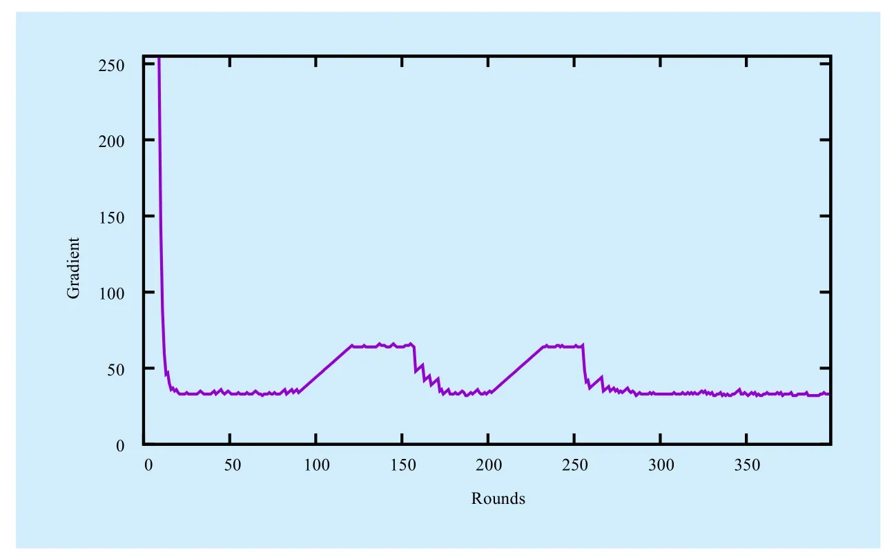
Fig. 10 Response to node movement
5.3.4 LPL 20%, large packet
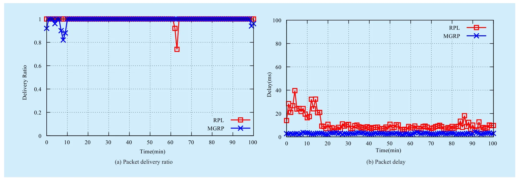
Fig. 11 No LPL, Small packet.
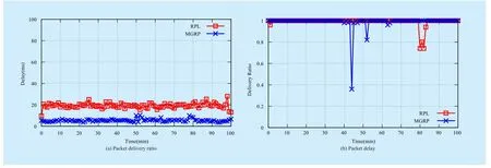
Fig. 12 No LPL, Large packet
In figure 14, PRL’s packet delay is a bit higher compared to delay in figure 14(b) due to increased payload size, while MGRP’s packet delay doesn’t change much.
5.3.5 LPL 5%, small packet
With low-power-listening duty-cycle of 5%,the sender should wait more time for the receiver wakes up. As a result, in figure 15(b),RPL’s packet delay significantly increases to about 200ms, while MGRP still remains lower delay about 40ms.
5.3.6 LPL 5%, large packet
In this case, the primary cause of packet delay is waiting for receiver wakes up. As figure 16(b) shows, packet payload size doesn’t affect much on packet delay compared to figure 15(b).
VI. CONCLUSION
In this paper, we present a multi-gradient routing protocol called MGRP for wireless sensor networks. It is concise, general purpose and fully distributed, supports multiple traffic patterns including end-to-end, many-to-one and one-to-many traffic. MGRP uses a simple and efficient gradient constructor substitutes traditional link estimator, which is responsive to network dynamics. The routing strategy in MGRP is straightforward. Packets are forwarded downward the gradient to the destination. Our experiment on real-world testbed proves MGRP has better performance than the state of the art routing protocol.
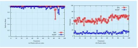
Fig. 13 LPL 20%, Small packet
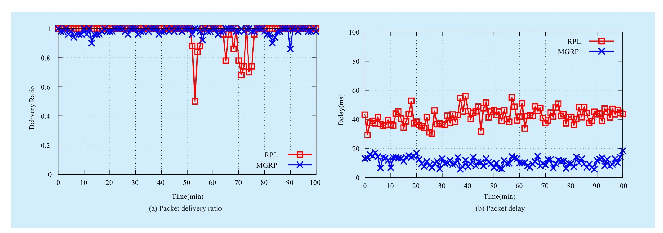
Fig. 14 LPL 20%, Large packet
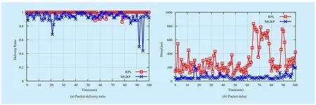
Fig. 15 LPL 5%, Small packet
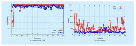
Fig. 16 LPL 5%, Large packet
ACKNOWLEDGEMENTS
This work is supported by National Key Technologies Research and Development Program of China under Grant No.2014BAH14F01, National Science and Technology Major Project of China under Grant No. 2012ZX03005007, National NSF of China Grant No. 61402372 and Fundamental Research Funds for the Central Universities Grant No. 3102014JSJ0003.
[1] KO J, ERIKSSON J, TSIFTES Net al, “Industry:Beyond Interoperability – Pushing the Performance of Sensor Network IP Stacks”,Proceedings of the 9th ACM Conference on Embedded Network Sensor Systems (Sensys), pp 1-11, 2011.
[2] HUI J W, CULLER D E, “IP is Dead, Long Live IP for Wireless Sensor Networks”,Proceedings of the 6th ACM Conference on Embedded NetworkSensor Systems (Sensys), pp 15-28, 2008.
[3] HUI J W, CULLER D E, “IPv6 in low-power wireless networks”,Proceedings of the IEEE, vol. 98,no. 11, pp 1865-1878, 2010.
[4] T.WINTER, THUBERT P, BRANDT Aet al, “RPL:IPv6 Routing Protocol for Low power and Lossy Networks”,draft-ietf-roll-rpl-19, pp 1-157, 2011.
[5] FERRARI F, ZIMMERLING M, MOTTOLA Let al,“Low-power wireless bus”,Proceedings of the 10th ACM Conference on Embedded Network Sensor Systems (Sensys), pp 1-14, 2012.
[6] FERRARI F, ZIMMERLING M, THIELE Let al, “Efficient network flooding and time synchronization with Glossy”,10th International Conference on Information Processing in Sensor Networks(IPSN), pp 73-84, 2011.
[7] DUQUENNOY S, LANDSIEDEL O, VOIGT T, “Let the tree Bloom: scalable opportunistic routing with ORPL”,Proceedings of the 11th ACM Conference on Embedded Networked Sensor Systems(Sensys), pp 1-14, 2013.
[8] GNAWALI O, FONSECA R, JAMIESON Ket al,“Collection tree protocol”,Proceedings of the 7th ACM Conference on Embedded NetworkedSensor Systems (Sensys), pp 1-14, 2009.
[9] LANDSIEDEL O, GHADIMI E, DUQUENNOY Set al, “Low power, low delay: opportunistic routing meets duty cycling”,Proceedings of the 11th International Conference on Information Processing in Sensor Networks (IPSN), pp 185-196,2012.
[10] SOCIETY I C. “IEEE Std. 802.15.4a-2007”,IEEE Standard Association, 2007.
[11] DUTTA P, DAWSON-HAGGERTY S, CHEN Yet al,“A-MAC: A Versatile and Efficient Receiver-initiated Link Layer for Low-power Wireless”,ACM Transactions on Sensor Networks, vol. 8, no. 30,pp 1-30, 2012,.
[12] ASHRAF F, VAIDYA N F, KRAVETS R H, “Any-mac:Extending any asynchronous mac with anycast to improve delay in wsn”,Proceedings of the 8th Annual IEEE Communications Society Conference on Sensor, Mesh and Ad Hoc Communications and Networks (SECON), pp 19–27, 2011.
[13] FONSECA R, GNAWALI O, JAMIESON Ket al,“Four-bit wireless link estimation”,Proceedings of the Sixth Workshop on Hot Topics in Networks(HotNets VI), pp 1-7, 2007.
[14] STEVENS W R, “TCP/IP illustrated (vol. 1): The Protocols”,Addison-Wesley, 1994.
[15] MOSS D, LEVIS P, “BoX-MACs: Exploiting physical and link layer boundaries in low-power networking”,Computer Systems Laboratory Stanford University, pp 1-12, 2008.
杂志排行
China Communications的其它文章
- A Novel Low Density Parity Check Coded Differential Amplitude and Pulse Position Modulation Free-Space Optical System for Turbulent Channel
- Direction of Arrivals Estimation for Correlated Broadband Radio Signals by MVDR Algorithm Using Wavelet
- Signal Path Reckoning Localization Method in Multipath Environment
- Adaptive Application Offloading Decision and Transmission Scheduling for Mobile Cloud Computing
- Degree-Based Probabilistic Caching in Content-Centric Networking
- Efficient XML Query and Update Processing Using A Novel Prime-Based Middle Fraction Labeling Scheme
