Status and development of vision sensors on intelligentized robotic welding technologies
2017-04-28CHENHuabinKONGMengLVNaXUYanlingCHENShanben
CHEN Huabin,KONG Meng,LV Na,XU Yanling,CHEN Shanben
(1.School of Material Science and Engineering,Shanghai Jiao Tong Univ.,Shanghai 200240,China;2.Shanghai-Fanuc Robotics Co.,Ltd.,Shanghai 201206,China)
Status and development of vision sensors on intelligentized robotic welding technologies
CHEN Huabin1,KONG Meng2,LV Na1,XU Yanling1,CHEN Shanben1
(1.School of Material Science and Engineering,Shanghai Jiao Tong Univ.,Shanghai 200240,China;2.Shanghai-Fanuc Robotics Co.,Ltd.,Shanghai 201206,China)
With the implementation of China Manufacturing 2025,welding manufacturing has been developed towards the digitization,informatization and intelligentization.Thus,the demand for information in welding process is significantly increasing. In this paper,we introduce some new research works and key technologies on intelligent welding field in the Institute of Intelligent Welding&Materials Precise Processing.The main research include:the research on autonomous guidance and welding path planning based on visual sensor,intelligent characterization of dynamic liquid welding pool,in-situ the measurement and multiscale calculation of the high temperature strain during welding process.The application of the above research development,to a certain,enrich and develop the connotation of intelligent welding technologies.It is expected that the results of intelligent visual technologies will be the beginning of welding intelligent manufacturing development.
visual sensor;intelligentized welding;robotic welding;welding automation;machine vision
0 Introduction
As the labor costs have gradually increased in recent years,the current Chinese economic mode based on cheap labor is hard to sustain.Therefore,more and more manufacturing enterprises have given special attention to welding automation technology,represented by welding robot.According to statistical data released by the international federation of robotics(IFR)in 2015,industrial robots will reach 268 thousand units up to 2020,about 30 percent of which will be employed in welding field,meaning over 24-billion-yuan worthy of a huge system integrationandintelligent welding market[1].WiththestrategyimplementationofmadeinChina2025,weldingmanufacturing system is developing towards integrate of digitize,networking and intelligence.Welding product is experiencing changes and developments with the direction of high performance,huge structure,long service and high reliability,which has significantly increased the demand for information during welding process[2].Intelligent welding technology,on the basis of information technology,is an interdisciplinary which integrates sensory information(seeing,hearing,touching),experiential knowledge(behavior of molten pool,arc sound,weld appearance),reasoningjudgment,weldingprocesscontrolandprocessoptimization.Breakingthroughkeytechnologyofintelligentized robotic welding is not only a developing direction but also a pressing need[3].Obviously,vision sensing is one of thekey factors making the transition from automation equipment to intelligent welding robots.At present,widely used welding robots are not as smart as welders,which means robots do not have full knowledge of welding procedure and cannot optimize welding process.Combined with cool consideration about crazy market proposed by Researcher Tianhu Song in IFWT’2016[4]several bottleneck problems about intelligentized robotic welding are proposed as follows:
(1)Welding sequence.It is difficult for welding robots to adaptively adjust welding sequence when the change of condition(deformation,misalignment,gap and so on)happens,which is beyond expectation.
(2)Identification of the initial welding position.It is not reliable to identify the initial welding position as it is susceptible to plant environment.
(3)Welding dynamic process.It is ineffective to adjust the response during welding process.
(4)Seam tracking.Visual tracking is susceptible to arc light.Moreover,there exist vision blind angle and tracking dead zone.
(5)Automatic path-layout of multi-pass welding.The adaptability for the welding groove is poor,and ability for adaptive welding layout and adjustment of technological parameters is scarce.
(6)Prevention from welding defections.It lacks active management for the generation of welding defections.
(7)Consistency of welding quality.It is short of sensing methods for charactering reliable on-line.
Though the change of plant environment and condition is inevitable,aforementioned factors,such as machining error,assembly error,welding deformation,fixture instability,have significant effects on welding quality,leading to the generation of defections.Eliminating the influence of uncertain factors on precise welding quality is an inevitable practical problems and bottleneck challenge to realize intelligent manufacturing of the welding[5].
Combined with researches reported by Intelligentized Robotic Welding Technology Laboratory in recent years,the paper introduces research achievements and application status of machine version in welding environment recognition,precise tracking,and dynamic process monitoring and welding quality control.
1 Identification of the initial welding position and seam tracking[6-7]
Due to the advantages of convenient,intuitive and rich information,visual information has been a difficult and attractive field in seam recognition and seam tracking,expected to be one of the most promising sensing methods in robotic welding.As an intelligent unit of robotic peripherals,the visual sensor has a significant role in improving flexibility of welding robots and feedback of plant environment.With the rapid development of computer technology,photoelectric sensor and image processing technology,visual sensors will play a leading role in decision making and predicting during welding process and building the intelligent system of welding robots.
1.1 Initial welding position identification and path planning based on vision sensor
In order to enhance the autonomous welding ability of the robot and give the robot a certain sense of self learning and decision-making ability,an arc welding robot system with a vision sensor and laser measurement function is set up on the FANUC arc welding robot platform,as shown in Figure 1.The system is composed of robot control and execution module,visual feedback module and Interface communication module.With the help of digital image processing technology,identification of weld seam feature point and 3D reconstruction of weld seam on the workpieces are realized,robot self-localization and intelligent recognition of weld joint are realized on the basis.
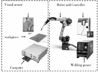
Fig.1 Arc welding robot experiment set-up
To realize the initial position of the robot and the welding seam recognition,it is necessary to establish the relationship between the image pixel coordinates and the coordinates of the target points,known as Vision system calibration,and the three links are camera calibration,line structured light calibration and hand eye calibration. The camera calibration is to establish the corresponding relationship between the 2D image points of the image plane and the spatial three-dimensional feature points and determine the camera internal imaging parameters: focal length,distortion parameters,the number of pixels per unit distance of the imaging plane etc.The purpose of hand eye calibration is to determine the relative position between the camera coordinate system and the tool coordinate system H,using the rotation matrix R and matrix T to describe.The line structured light calibration describes the structure of the line structured light plane in the camera coordinate system relationship,as the description of plane equation AX+BY+CZ+D=0 so to get the plane equation parameters.
For the case of flat butt joint,the initial welding position is defined by edge intersection method,Specific algorithm steps:two-step method is used to locate the initial welding position.Then,the local area of the initial welding position is filtered,image segmentation,pixel separation,linear fitting to get the initial weld position image coordinates.
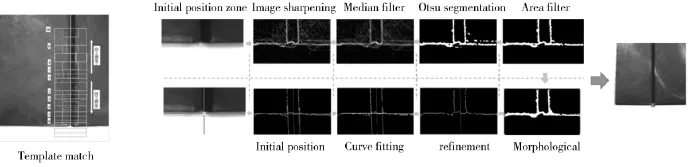
Fig.2 Image processing flow
Next,the coordinates of feature points were obtained by processing the laser stripe images.With flat butt (line,s-shaped)weld recognition as an example,combined with the parameter results of visual system mentioned above,the 3D coordinates were obtained under the TCS and WCS.When the welding robot is at A point,the pose parameters are[XA,YA,ZA,WA,PA,RA]T,when at B point,the pose parameters are[XB,YB,ZB,WB,PB,RB]T,the moving speed of the robot is v0(mm/s),and the interval time between capturing two pictures is Δt.The robot goes from point A to B,the camera captures n pictures during this time.Set a welding point coordinates of the points in image i(i=1~n)as[ui,vi]T,combined with the camera inner-parameter K and the structured-light plane equation X+BY+CZ+D=1,so to get the coordinates of feature points in CCS as[Xti,Yti,Zti]T.According to the hand eye calibration and robot pose parameter,the 3D coordinates of feature points can be obtained under the TCS as [Xti,Yti,Zti]Tand under the WCS as[Xwi,Ywi,Zwi]T.Figure 3 shows the 3D laser scanning reconstruction of the line weld and S shaped weld,the translational velocity of the robot TCP is 20 mm/s,and the adjacent camera capturing interval is 40 ms.

Fig.3 Result of 3D reconstruction for broken-line welding seam
1.2 Seam tracking based on active vision
The key process of laser tracking is visual processing of laser stripe collected by robot laser system.This procedure consists of image preprocessing of laser stripe,including ROI selection,filtering,image morphology operation and adaptive threshold segmentation,the extraction of center point of laser line and test on typical weld joint profile.Figure 4 shows process results of the intact image or image with trivial arc noise.It is concluded that for typical weld seam and weld joint profile,the proposed visual sensing system can acquire desired feature point of weld joint center.

Fig.4 Feature point of the laser stripe
However,in the actual welding process,due to the strong electric arc and splash effect,resulting in much noise in some images,the above algorithm can't obtain the weld characteristic information stably and reliably,shown in Figure 5.

Fig.5 Arc interference of the laser stripe
To ensure the continuity and reliability of welding seam tracking,the two methods are usually used in Engineering,one way is increasing the visibility distance of laser sensor or installing additional shielding plate,another way is improving the algorithm of the image processing software for selecting and filtering the image and the specific algorithm design process is as follow:
(1)Calculate the average gray value of the image,if the gray value of the image is larger than the normal image of a certain proportion(this paper selected 30%as a threshold)then give up the current image processing,turning to the next image processing.
(2)For V groove weld,set the weld width threshold.Under the condition that the weld width is less than the setting threshold,giving up the current image processing,turning to the next image processing.
(3)Since the weld deviation is continuous,and the deviation value between adjacent images is close,for the value of the mutation point(set a certain threshold),giving up the current image processing,turning to the next image processing.
According to the weld deviation calculated,on one hand the controller can be designed for seam correction,on the other hand,for the industrial robot,the robot controller can complete interpolation and trajectory correction,combined with communication protocol provided by the manufacturers.In addition,as a frame for distributed processing,ROS(Robot Operating System)can receive and release all types of sensing information,so ROS sets a uniform interface standard for robots currently.
On the basis of the developed visual sensors and the identifiable communication protocol by FANUC robot,we can further conduct an“ask-answer”development mode for swing and variable clearances butt-welding(See Figure 6).The query contents mainly include:offsets(X,Y,Z),weld width(for example,gap),mismatch,area and so on.
2 Intelligent characterization of liquid weld pool[8]
With the aid of vision sensing system,clear pictures of welding melted pool can be acquired online. Generally speaking,the geometric characteristics of welding pool including the weld width,area have a close connection with weld formation.Take the variable polarity plasma arc welding(VPPAW)as an example,welding current or voltage has some internal relationship with the geometric features of liquid pool.As seen in Figure 7,the area and width of backside keyhole increase with the addition of welding current.

Fig.6 Adaptive swing seam tracking with gradient gap
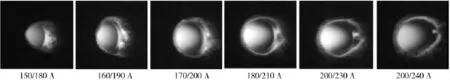

Fig.7 Key-hole image of VPPAW
Based on the part-based model for image recognition,it can adaptively obtain the feature points of left/right edges,and then extract the complete keyhole edge using ellipse fitting algorithm,the complete steps can be seen in Figure 8.Furthermore,the keyhole characteristics including keyhole length(L)and area(A)can be defined to give the basic description of actual penetration status.At first stage,the workpiece is not fully penetrated and the keyhole has not formed due to low heat input,then with the increasing of heat input,the opening keyhole diameter rapidly increases and begins to stabilize.With a higher heat input,the VPPA keyhole welding process gets into the cutting process.
3 Visual in-situ characterization of HAZ high temperature strain[9-10]
The measurement method of weld strain can be divided into connect and non-contact measurement,the method of non-contact measurement system mainly includes optical interferometry,digital image correlation and so on.This paper introduces a new measurement method of weld strain which called Digital Image Correlation Method(DIC).AdetailedcalculatingflowforweldstrainanddeformationbasedonDICtechniqueisgivenasfollows:
(1)Divide into several subsets in an image prior to deformation,and then divide into a bigger searching zoneafter deformation to describe the subset shape based on the shape function.

Fig.8 Images processing of VPPAW keyhole and edge fitting
(2)Find the possible subsets in the searching zone through a search algorithm,and then compute the evaluation function between each searched subset after and prior to deformation,the maximal correlation coefficient of all subsets can be taken as the deformed subset after searching.
(3)Calculate the displacement results and the strain values in a single specklegrm corresponding,then continue this process including divide into subsets,search and match.Finally,the principal strain of welding can be calculated.
Figure 9 shows the high temperature strain of TIG heat-affected zone of 304 stainless steel.Compared to conventional DIC characterization for welding strain,the method adopted in this paper can solve the problems of ablation and arc disturbance in a high-temperature weld speckle image to some extent.
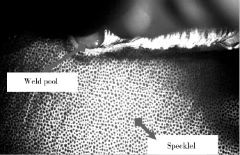
Fig.9 Speckle and weld pool image of 304 stainless steel during arc welding
Appling first-order shape function to describe the subset shape after deformation:

Where α is determined by the location change in x-axis;β is determined by the location change in y-axis;ux,uy,vx,vyare the derivatives of lateral displacement u and longitudinal displacement v with respect to x-axis and y-axis respectively.The shape function quotes the hypothesis of deformation continuity and considers the relative position relationship between points.
Based on the plastic flow theory of Mises,the strain equation can be described as:

εPis mechanical strain,εTis thermal strain,εXis phase transformation strain which is small and it is usually to be neglected.Therefore,the mechanical can be expressed as:

Figure 9 shows the high-temperature strain contour for welding line near line section of 304 stainless steel. The visual representation and computing results of total strain,thermal strain and mechanical strain are extremely significance to the model of welding residual stresses.Moreover,the DIC technique can record the change of strain distribution over time and illustrate the evolution law of total strain in welding process.As depicted in Figure 9,when the liquid pool flows toward the observation area,the strain of εxxdirection increases from zero to the maximum;as the welding molten pool flows away from the observation area and stabilizes gradually,the strain of εyydirectioncanreachthemaximum(negativevalue)andthenstabilizes gradually.Generally,the high-temperature strain of 304 stainless steel is compressive strain.
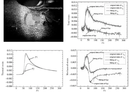
Fig.10 Curve of high-temperature strain and mechanical strain of 304 steel
4 Conclusions
Modern welding manufacturing needs to meet the requirements for transition and upgrading,innovative development and realize the leaped transformation of digital and intelligent welding manufacturing.With the continuous development and updating of sensor technology,image processing technology and machine vision theory,it plays an increasingly important role in welding assembly inspection,process monitoring and joint quality evaluation.The key technology of intelligent welding supported by visual information:autonomous guidance and welding path planning based on visual sensor,intelligent characterization of dynamic liquid welding pool,in-situ the measurement and multiscale calculation of the high temperature strain during welding process.It enrich and develop the connotation of intelligent welding technologies.
Acknowledgments
The authors gratefully acknowledge the supports of the National Natural Science Foundation of China underGrant No.51575348 and 51275301.They wish to thank Dr.Yiming Huang,Di Wu and Kai Chen for useful advice on this paper.
[1]China Welding Society(CMES),China welding technology roadmap[M].Beijing:China science&technology press,2016.
[2]Tzyh-Jong Tarn,Shanben Chen,Gu Fang,Robotic Welding,Intelligence and Automation[M].Springer,Lecture Notes in Electrical Engineering 88,2010.
[3]Tianhu Song,Towards the Digitalization of Welding Manufacturing[J].Welding Technology,2016,45(5):15-17.
[4]Tianhu Song,YonghuaLiu,ShujunChen.DiscussiononR&DandApplicationof Robot Welding Technology[J].Welding and Joining,2016,518(8):1-10.
[5]Shanben Chen,Na Lv.Research evolution on intelligentized robotic welding technologies[J].Electric Welding Machine,2013,43(5):28-36.
[6]Seji Huang,YanlingXu,XuejunYang.ROIWeldFeatureExtractionAlgorithmofReal-Time Tracking[J].JournalofShanghaiJiaoTong University,2016,50(12):54-57.
[7]Xuejun Yang,Yanling Xu,Shanben Chen.A Recognition Algorithm for Feature Points of V-Groove Welds Based on Structured Light[J].Journal of Shanghai JiaoTong University,2016,50(10):1573-1577.
[8]Wu D,Chen H B,Chen S B.Monitoring of weld joint penetration during variable polarity plasma arc welding based on the keyhole characteristics and PSO-ANFIS[J].Journal of Materials Processing Tech.,2016(239):113-124.
[9]Kairong Zhou,Jian Chen,Huabin Chen.Characterization and Calculation of High Temperature Strain in Gas Tungsten Arc Welding Based on in Situ Measurement[J].Journal of Shanghai JiaoTong University,2016,50(10):1588-1591+1596.
[10]X Zhou,HB Chen,J Chen,et al.High temperature full-field strain measurement based on digital image correlation during arc welding[J].IEEE Workshop on Robotics and its Social Impacts,2016:203-207.
TG409
A
1001-2303(2017)03-0008-09
献
CHEN Huabin,KONG Meng,LV Na,et al.Status and development of vision sensors on intelligentized robotic welding technologies[J].电焊机,2017,47(03):8-16.
2017-03-10
陈华斌(1976—),男,安徽安庆人,副教授,博士,主要从事焊接智能化及机器人系统工程等方面的教学和科研工作。
10.7512/j.issn.1001-2303.2017.03.02
