Influence of Blade Thickness on Transient Flow Characteristics of Centrifugal Slurry Pump with Semi-open Impeller
2016-12-09TAOYiYUANShouqiLIUJianruiZHANGFanandTAOJianping
TAO Yi, YUAN ShouqiLIU JianruiZHANG Fanand TAO Jianping
Influence of Blade Thickness on Transient Flow Characteristics of Centrifugal Slurry Pump with Semi-open Impeller
TAO Yi1,*, YUAN Shouqi1, LIU Jianrui1, ZHANG Fan1, and TAO Jianping2
1 National Research Center of Pumps and Pumping System Engineering and Technology, Jiangsu University, Zhenjiang 212013, China;2 Yixing Taoye Nonmetallic Chemical Machinery Factory Co. Ltd., Wuxi 214222, China
As the critical component, the impellers of the slurry pumps usually have blades of a large thickness. The increasing excretion coefficient of the blades affects the flow in the impeller resulting in a relatively higher hydraulic loss, which is rarely reported. In order to investigate the influence of blade thickness on the transient flow characteristics of a centrifugal slurry pump with a semi-open impeller, transient numerical simulations were carried out on six impellers, of which the meridional blade thickness from the leading edge to trailing edge varied from 5-10 mm, 5-15 mm, 5-20 mm, 10-10 mm, 10-15 mm, and 10-20 mm, respectively. Then, two of the six impellers, namely cases 4 and 6, were manufactured and experimentally tested for hydraulic performance to verify the simulation results. Results of these tests agreed reasonably well with those of the numerical simulation. The results demonstrate that when blade thickness increases, pressure fluctuations at the outlet of the impeller become severe. Moreover, the standard deviation of the relative velocity in the middle portion of the suction sides of the blades decreases and that at the outlet of the impeller increases. Thus, the amplitude of the impeller head pulsation for each case increases. Meanwhile, the distribution of the time-averaged relative flow angle becomes less uniform and decreases at the outlet of the impeller. Hence, as the impeller blade thickness increases, the pump head drops rapidly and the maximum efficiency point is offset to a lower flow rate condition. As the thickness of blade trailing edge increases by 10 mm, the head of the pump drops by approximately 5 m, which is approximately 10 % of the original pump head. Futhermore, it is for the first time that the time-averaged relative flow angle is being considered for the analysis of transient flow in centrifugal pump. The presented work could be a useful guideline in engineering practice when designing a centrifugal slurry pump with thick impeller blades.
centrifugal slurry pump, blade thickness, transient flow characteristics, time-averaged relative flow angle, semi-open impeller
1 Introduction
The centrifugal slurry pumps are widely used in industries including nonferrous metal smelting, mining, and environmental engineering because of their features such as low flow rate, high pressure, and low manufacturing cost. In general, the impellers applied in the centrifugal slurry pumps are manufactured with relatively thick blades and without a front shroud because of the severe abrasion caused by the high concentration of solid particles in the fluids that need to be pumped. Moreover, the flow in the centrifugal slurry pumps is characterized by a strong jet-wake flow structure in the impeller and the unsteady interactions between the rotating impeller and the stationary volute tongue. The jet-wake flow structure and the unsteady interactions significantly influence the overall hydraulic performance of the pump.
Plenty of research has been conducted to reveal the relationships between the flow fields of centrifugal pumps and geometric parameters, such as blade number, blade wrap angle, blade outlet angle, and blade outlet width of the impeller[1–6]. Until now, studies of impeller blade thickness have been mainly carried out on axial flow pumps, mixed flow pumps, and wind turbines[7–11]. However, similar studies on centrifugal pumps are rare. Several indicative works have been performed over the last few years. YANG, et al[12], captured the velocity and pressure distribution in three impellers with different blade thickness variation patterns in a petrochemical centrifugal pump and determined that the intensity of jet-wake flow structure would be stronger with the increase in blade outlet thickness. A numerical simulation based on Fluent and an experiment on a model stainless-steel stamping well-pump were conducted by WANG, et al[13], and the results show that the maximum efficiency point of the pump shifts to a lower flow rate and that the internal turbulence losses increase with the increase in impeller blade thickness. MU, et al[14], numerically simulated six impellers with different blade thicknesses and calculated their hydraulic performance; the results helped them conclude that both the head and efficiency were lowered with an increase in blade thickness; however, the head decreased at a lesser rate than the efficiency. JIN, et al[15], obtained the optimum thickness of a low specific speed centrifugal impeller and postulated that a larger blade thickness had a direct impact on the effective flow angle at the exit of the impeller, thus affecting the hydraulic characteristics of centrifugal pumps. CHEN, et al[16], designed five impellers with different blade thicknesses all other geometric parameters being identical. Through the numerical simulation that was based on the standard-equation and the SIMPLE algorithm, they determined that the highest efficiency increased slightly when the blade thickness was increased; simultaneously, the optimal efficiency point moved to a lower flow rate condition. Moreover, GAO, et al[17], investigated the influence of the blade trailing edge profile on the performance and unsteady pressure pulsations in a low specific speed centrifugal pump. They concluded that trailing edges with an ellipse on the pressure side and those with an ellipse on both sides contribute toward reducing the pressure pulsations and vorticity distribution, thus significantly improving the pump efficiency. From these conclusions, it can be observed that although slurry pump impellers with a thicker impeller blade have a significantly longer service life, the influence of blade thickness on the hydraulic performance of the pump should be given due consideration.
It is known that the complex flow at the outlet of the impeller appears as a circumferential distortion due to the interactions between the rotating blades and the volute tongue and is a combination of turbulence, secondary flows, and leakage flows. YANG, et al[18], presented the effects of the radial gap between the impeller tips and volute tongue, which influences the performance and pressure pulsations of a pump functioning as a turbine. He demonstrated that the amplitude of high frequency unsteady pressure pulsation within the volute decreases when the the radial gap increases, while the amplitude of low frequency unsteady pressure pulsation within the impeller remains unchanged. CAI, et al[19], investigated the flow field in a centrifugal pump with a large tongue gap and back blades and revealed that the flow from the main blade passage interfered with that from the back blade passage. Moreover, a swirling flow was found in the volute. Therefore, the investigation of the transient flow characteristics of the centrifugal pump with a varying blade thickness is essential and is urgently required. In this paper, a horizontal centrifugal slurry pump with an annular volute case was designed to be the research object. Six impellers differing in blade thickness were carried out and numerically simulated. Thus, both the transient flow within the entire flow field and hydraulic performance of the pump have been achieved. Based on the analysis of the simulation results, two of the six impellers were trial-manufactured and experimentally tested. By comparing with experimental results, the simulation results were verified to be reliable. Furthermore, the conclusions obtained could provide references for the design of the impellers for centrifugal slurry pumps.
2 Model Pump
2.1 Design specifications
The model pump is a horizontal centrifugal pump with a single stage and single suction inlet. The structure of the model pump is shown in Fig. 1.
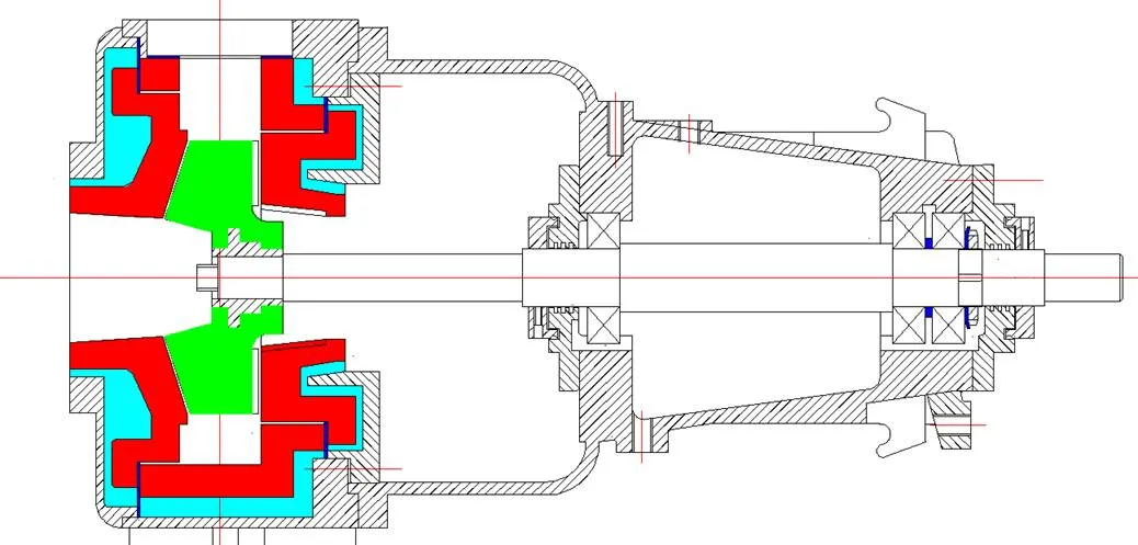
Fig. 1. Structure of the model pump
The design specifications of the model pump are listed in Table 1. Meanwhile, the specific speed of the model pump is 103.

Table 1. Design specifications of the model pump
2.2 Impeller design
The impeller is untwisted, without a front shroud, and is designed according to the empirical correlation method, which is based on a number of high-performing hydraulic models. The primary geometric parameters of the impeller that meet the design requirements listed in Table 1 are listed in Table 2. Furthermore, the profile of the blade pressure side was established using the variable angle spiral method.
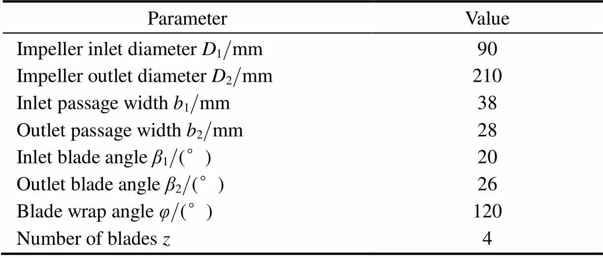
Table 2. Primary geometric parameters of the impeller
2.3 Blade thickness
The six impellers, which vary in blade thickness and are identical with respect to all other parameters summarized in Table 2, were studied to investigate the influence of the impeller blade thickness on the transient flow field and hydraulic performance of the pump. The thicken process started from the blade pressure side towards a direction opposite to that of the rotation. The blade meridional thickness, namelym, from the leading edge to the trailing edge in each case are 5-10 mm, 5-15 mm, 5-20 mm, 10-10 mm, 10-15 mm, and 10-20 mm, respectively.
3 Numerical Simulation
3.1 Computational domain
As is shown in Fig. 2, the computational domains consist of five regions, namely the inlet pipe, gap (3 mm wide) between impeller and volute casing, impeller, annular volute, and back blade passages. Hexahedra structured meshes were applied in all the computational domains, providing the advantages of rapid convergence and high precision. The inlet and outlet pipes of the pump were extended in a manner so that the flow at the inlet of the impeller could avoid the impact of the inlet boundary condition, and the flow at the outlet of the volute could be fully developed.

Fig. 2. Computational domains and grid meshing
3.2 Mesh independence
As illustrated in Fig. 2, the grids near the wall, especially the blade surface and the volute tongue, have been refined in order to ensure a high precision simulation. The mesh independence analysis of the base impeller with a blade thickness of 5-10 mm at the design working condition was conducted to examine the influence of the grid number on the pump performance with the blocking strategy remaining unaltered. It can be observed in Fig. 3 that when the grid number reaches 4 million, the variation in the pump performance caused by the grid number is less than 1 %. Hence, a final grid with 4.02 million cells was used to define the entire computational domain for each of the six impellers. For the purpose of reducing the time required, the mesh independence analysis was conducted through a steady simulation.
Fig. 3. Mesh independence analysis
3.3 Simulation method
Since the computational domains contain both stationary and rotational regions, the multiple reference frame has been used. The passages in the impeller and those between the back blades were set as rotating with a rotational speed of 2900 r/min, and the other regions that include the inlet pipe, gap, volute casing and outlet pipe were set as stationary. The transient rotor-stator model was attached to the interfaces between the rotating and stationary regions[20].
Considering that a backflow may appear at the outlet of the volute in a centrifugal pump, the outlet boundary was set as opening, with a specified static pressure[21]. Moreover, an axial velocity based on the flow rate was provided at the inlet boundary. All the walls in the computational domains were set as no-slip and with a roughness of 0.2 mm.
A high-resolution technique was used for the discretization of the advection scheme and turbulence terms. The second-order backward euler method was applied for the transient scheme. The governing equations were closed using the-turbulence model, which is applicable to fully developed turbulent flows with a high Reynolds number and mainly based on the turbulent kinetic energy and diffusion rate[22]. The low Reynolds number flow in the near-wall regions were resolved by the standard wall function.
For the purpose of high accordance with the practical situation, the boundary configuration that with a specified inlet total pressure and a specified outlet mass flow rate were employed to run a simulation. The simulation underwent iterations until the total pressure observed at both the inlet and outlet boundaries tended to be stable so that the static pressure at the aforementioned opening outlet boundary could be set according to the results of this simplified simulation. The convergence precision of the residuals was set as 10-5, and the observation of the integrated quantities of the total pressure at both inlet and outlet boundaries were also chosen for the convergence of the solution. The time step was set as 0.000 172 414 s, during which the impeller rotates for 3 °, implying that the rotational period of the impeller covers 120 time steps. Approximately 10 impeller revolutions were calculated to enable convergent results, and data on the 11thimpeller revolution was used to analyze the transient flow in each case.
4 Numerical Results and Discussions
4.1 Hydraulic performance comparison
The hydraulic performance curves of the model pump with the varying impeller blade thickness have been obtained using a numerical simulation under multiple working conditions. The variation of head and efficiency against the non-dimensional flow rate of the model pump with the different impellers are illustrated in Fig. 4. Generally, the head and efficiency of the pump decrease with an increase in the impeller blade thickness. Moreover, the maximum efficiency point is offset to a lower flow rate condition.
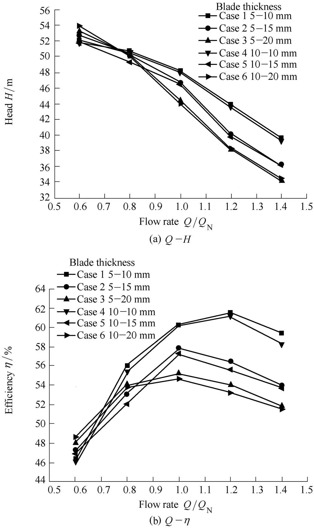
Fig. 4. Comparison of hydraulic performance curves
The head in case 1 is the highest with a maximum value of 48.23m at the design working condition with a flow rate of 100 m3/h. The head in case 4(47.95 m) is approximately equal to that in case 1, but lower by 0.25 m. The heads in cases 2 and 5 are 46.48m and 46.74m, respectively, and those in cases 3 and 6 are 44.38m and 44.02m, respectively. Among the six cases, case 1 has the maximum efficiency with a value of 60.2%.The next highest efficiency is that of case 4(60.08 %). The efficiencies of cases 2 and 5 are approximatelyequal with values of 57.85 % and 57.33 %, respectively. The lowest two efficiencies of 55.23% and 54.68% are of cases 3 and 6, respectively. Thus, the six cases can be divided into three groups, that is, cases 1 and 4, cases 2 and 5, and cases 3 and 6, according to the head and efficiency curves. As can be observed, the outlet blade thickness has a close relationship with the group division, which implies that the outlet blade thickness has a higher influence on the head and efficiency (especially so on the latter) of the pump than the inlet blade thickness.
Fig. 5 illustrates the pulsation of the impeller head and pump head during a rotation period. It can be observed that the impeller head pulsation in each case appears with a periodicity, which has four peaks and four valleys because of the interaction between the blade trailing edges and volute tongue. With an increase in blade thickness, the amplitude of the impeller head pulsation in each case increases while the amplitude of the pump head decreases. The pulsation of the impeller head and pump head in the six cases can also be divided into three groups according to the difference in blade trailing edge thickness, which confirms that the blade trailing edge thickness has a higher influence on the head. The deviations between the impeller head and pump head are almost identical in each case, which implies that the head loss in the volute is not the main cause of the difference in the head and efficiency curves. Hence, a sophisticated analysis of the transient flow in the impeller is put forward in the following section.
4.2 Transient flow analysis at design condition
The instantaneous pressure on a grid node in a transient numerical simulation can be decomposed into two parts: the time-averaged pressurethat is given in Eq. (1) and the periodic pressurethat is given in Eq. (2). With the purpose of an intuitive display of the pressure fluctuation in the impeller in each case, a non-dimensional time-averaged pressure fluctuation coefficientCis defined in Eq. (3) and calculated by using the standard deviation of pressure in the software CFX-Pre:

(2)
(3)
whereis the total number of time steps during an impeller revolution, which equals 120 in this study,is the time step,is the density of water, and2is the rotation velocity at the trailing edge of the impeller[23].
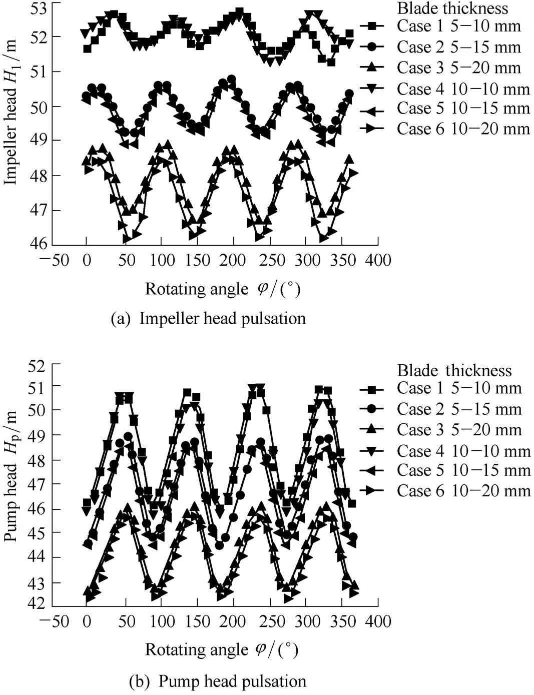
Fig. 5. Head pulsation during a rotation period
The distribution of the time-averaged pressure fluctuation coefficientCon the mid plane of the impeller in each case is illustrated in Fig. 6. It can be observed that theCvalues increase from the inlet to the outlet of the impeller, and the regions with the relatively larger values ofCare located at the middle and outer parts of the blade pressure sides in all the six cases.With the increase in blade thickness of trailing edges, the regions with high pressure pulsation at the middle part of blade pressure sides offset towards the outlet of the impeller and combine with the outer regions with relatively largerCvalues. Simultaneously, theCvalues at the suction region of the impeller decreases. In general, theCvalues increase with the increase in radius, and the pressure fluctuations at the pressure sides of the blades are more significant than those at the suction sides in the region of equal radius. In addition, theCvalues at the outlet of the impeller become larger with the increase in blade thickness of the trailing edges, thus explaining the impeller head pulsation illustrated in Fig. 5. The effect of the blade leading edges on the pressure pulsation in the impeller is insignificant in comparison to the effect of the blade trailing edges thickness.
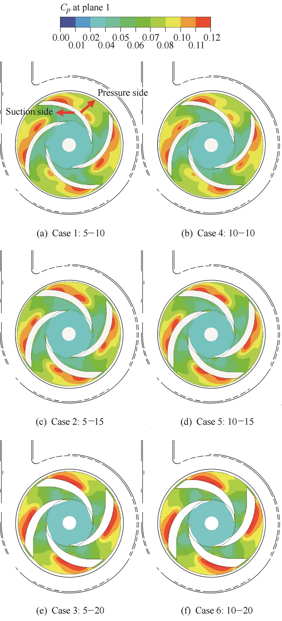
Fig. 6. Counter ofCon the mid plane of impeller for each case
Similar to the pressure fluctuations, the instantaneous relative velocityon a grid node in a transient numerical simulation can also be divided into two parts: the time-averaged relative velocitythat is given in Eq. (4) and the periodic relative velocitythat is given in Eq. (5). In order to study the transient velocity field in the impeller in each case, the standard deviation of relative velocity in the impellerdivis defined in Eq. (6) and calculated in the software CFX.


whereis the total number of time steps during an impeller revolution, which equals 120 in this study.
Fig. 7 illustrates the distribution of the standard deviation of relative velocitydivon the mid plane of the impeller in each case. In all the six cases, the regions with the maximum values ofdivare located at the middle part of the suction sides of the blades, and the minimum values occur at the suction sides of the leading edges. Moreover there is a large region at the pressure side of each blade near the outlet of the impeller, where the variation ofdivis relatively large. With an increase in radius,divinitially increases along the pressure side and then decreases along the suction side. With an increase in the blade thickness of the trailing edges, the value ofdivat the middle part of the suction sides of blades decrease; however,divat the outlet of the impeller increases similar toC, leading to a larger amplitude of the impeller head. The effect of the blade leading edges on the transient velocity field is also limited.
-
On the basis of the velocity triangle theory of centrifugal pumps, the relative flow angle denotes the angle between the relative velocity vector and rotation velocity vector, which are available in CFX-Post. In order to evaluate the flow in the passage of the impeller quantitatively, the relative flow angle is calculated using the law of cosines on the two aforementioned velocity vectors. The velocity triangle is illustrated in Fig. 8. Considering the complexity of analyzing the distribution of the relative flow angle at each time step, the time-averaged relative flow angle is calculated in Eq. (7):
The distribution of the time-averaged relative flow angle in the impeller in each case is illustrated in Fig. 8. In all the six cases, the relatively larger values ofare located near the suction sides of the impeller blades. The relatively smaller values ofappear at the suction side of the leading edge, at the outlet of the impeller, and at the middle region of the impeller flow passage in cases 1,2, and 5. The vane angle at the pressure side of the blade varies from 20 ° at the leading edge to 26 ° at the trailing edge. Thus, in Fig. 8, the flow in the regions with highvalues is shiftingfrom the pressure side towards the suction side, and the flow in the regions with lowvalues is shifting towards the pressure side. If the value ofapproximates to zero, it implies that there occurs a backflow or vortex in this region. If the value ofis between 20 ° and 26 °, it implies that the flow is as expected and highly favorable. The comparison between the counter ofand the relative velocity vector distribution on the mid plane of the impeller, which can be observed in Fig. 8, verifies the relationship between the time-averaged relative flow angle and the flow pattern of the fluid.
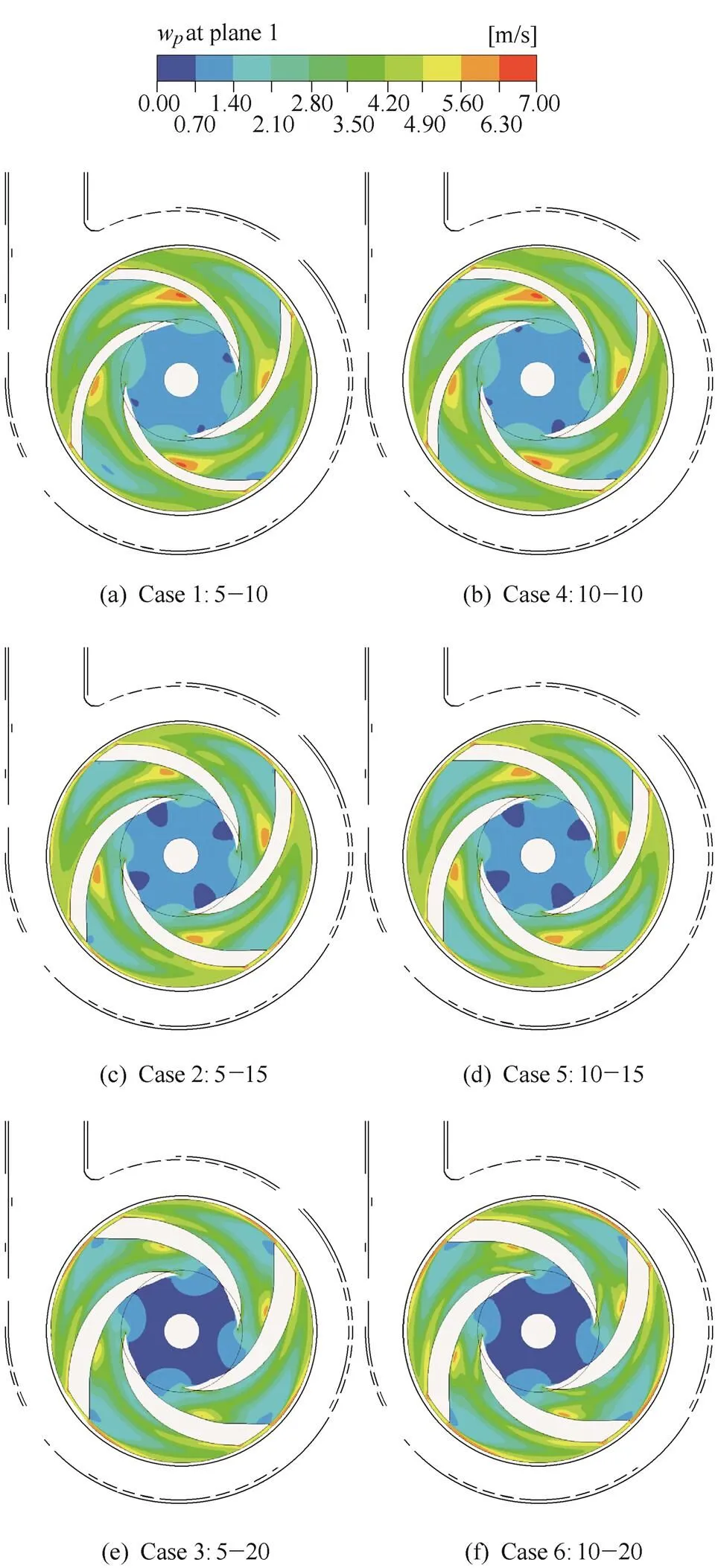
Fig. 7. Counter ofdivon the mid plane of impeller for each case
With the increase in the thickness of the blade trailing edges, the distribution ofbecomes less uniform, and the values ofat the outlet of the impeller decrease according to the velocity triangle theory, resulting in a lower value ofu2which is the tangential component of the absolute velocity at the outlet of the impeller. Hence, the pump head decrease with an increase in blade trailing edge thickness, which is captured by the basic equation of pumps (Eq. (8)). In addition, the values ofbecome larger at the leading edge with an increase in the blade thickness. This happens because the area of the flow passage decreases leading to a larger value ofm, which is the meridional component of the absolute velocity when the flow rate remains unaltered. The increased kinetic energy of the fluid results in a decrease in static pressure, which may cause cavitation.
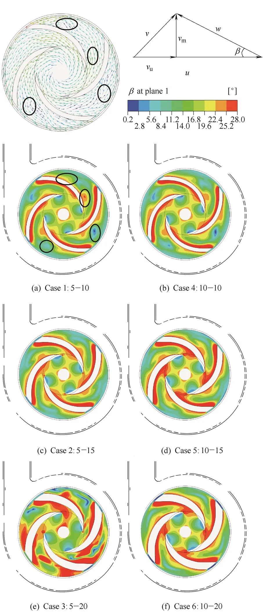
Fig. 8. Counter ofat the mid plane of impeller for each case
(8)
5 Experiment
The test rig was set up with the aim of verifying the accuracy of the numerical simulation. The test rig is illustrated in Fig. 9. The impeller in cases 4 and 6, with blade thicknesses 10-10 mm and 10-20 mm, respectively, have been manufactured for the experiment. The opentype test rig consists of two pressure transmitters with the measurement error of 0.25 % mounted at the inlet and outlet pipes, a turbine flow meter with a measurement error of 0.5 %, a torque meter with a measurement error less than 0.1 %, a valve at the outlet pipe to adjust the flow rate of the pump, a power distributing cabinet, a data acquisition instrument, and a reservoir open to air and the pipelines. The test rig processes the identification of a national grade 1 precision(GB/T 3216-2005) from Department of Science and Technology in the Jiangsu province of China.
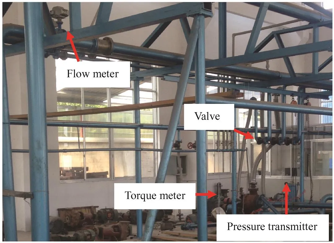
Fig. 9. Picture of test rig
杂志排行
Chinese Journal of Mechanical Engineering的其它文章
- Surface Topography and Roughness of High-speed Milled AlMn1Cu
- Digital Evaluation of Sitting Posture Comfort in Human-vehicle System under Industry 4.0 Framework
- Thermo-physical Characteristics of Nickel-coated Aluminum Powder as a Function of Particle Size and Oxidant
- Effect of Magnetic Field on Forced Convection between Two Nanofluid Laminar Flows in a Channel
- Gas Film Disturbance Characteristics Analysis of High-Speedand High-Pressure Dry Gas Seal
- Method for Evaluating the Reliability of Compressor Impeller of Turbocharger for Vehicle Application in Plateau Area
