Design of trotting controller for the position-controlled quadruped robot①
2016-12-05ZhangGuoteng张国腾LiuJinchangRongXuewenLiYibinChaiHuiLiBinZhangHuiZhangShuaishuai
Zhang Guoteng (张国腾):Liu Jinchang,Rong Xuewen:Li Yibin:Chai Hui,Li Bin:Zhang Hui:Zhang Shuaishuai
(*School of Control Science and Engineering:Shandong University:Jinan 250061:P.R.China)(**High Technology Research Development Center:Ministry of Science and Technology of the People’s Republic of China:Beijing 100044:P.R.China)
Design of trotting controller for the position-controlled quadruped robot①
Zhang Guoteng (张国腾)*:Liu Jinchang*To whom correspondence should be addressed.E-mail:liujc@htrdc.comReceived on Apr.1,2015**,Rong Xuewen*:Li Yibin*:Chai Hui*,Li Bin*:Zhang Hui*:Zhang Shuaishuai*
(*School of Control Science and Engineering:Shandong University:Jinan 250061:P.R.China)(**High Technology Research Development Center:Ministry of Science and Technology of the People’s Republic of China:Beijing 100044:P.R.China)
This work presents a controller designed for position-controlled quadrupedal dynamic locomotion:aiming at simple and robust trotting control.The controller takes the torso attitude angles and velocities into planning foot trajectories.Firstly design of the servo motor actuated quadruped robot is introduced and the kinematic equations are deduced.Then a scheme is presented for controlling the robot torso attitude based on the virtual leg model.Furthermore:it demonstrates the design of the controller which enables the robot to have a wide range of trotting gaits and omni-directional motions.Finally:results of robust trotting in various speeds:path tracking and push recovery in simulation are reported:and results of trotting on real quadruped robots will be studied.
quadruped robot:position control:torso attitude:foot trajectory:trotting locomotion
0 Introduction
Legged robots have shown great superiority in terms of agility and versatility compared to their wheeled or tracked counterparts.They are able to navigate on much more uneven and rough terrains.These capabilities of legged robots have made it a new hot spot in robots research.Nevertheless:legged robots are more complicated in structure and difficult to control than wheeled or tracked robots.The theories concerned with legged robots are still in the development stage[1].
Legged animals in nature could keep balance during motions even after they suffer from unexpected disturbances.To date:lots of research have been made towards bridging the gap between locomotivity and balancing skills of legged robotic systems and that of real animals.The most well-known intuitive method for controlling legged robots is the three part locomotion algorithms developed by Raibert[2,3].The most famous quadruped robots built by Boston Dynamics:BigDog[4]and LS3[5]are believed being developed by Raibert’s three-part locomotion algorithms[6]though no details about the control methods have been published.Besides:quadruped robots like TITAN-VIII[7]or LittleDog[8]took the ZMP (zero moment point) method in their locomotion control.The CPG-based neural network with reflex feedbacks and interconnections qualified the Tekken robot with impressive trotting skills[9].The robot HyQ was controlled by a reactive controller consisting of a CPG-based trajectory generator and an attitude controller[10].And the Autonomous Systems Laboratory combined with virtual model control:PD controller and virtual forces in controlling their quadruped robot StarlETH[11].
Though some achievements have been got in the locomotion and balance control of legged robots:there is still a long way to go.The algorithms mentioned above generally need precise sensors:sophisticated computing:advanced actuators and possess force-control sections.These qualifications are unavailable for the ”civilian-style” robots.
In 2012:Center for Robotics of Shandong University developed a servo motor actuated small mammal bionic quadruped robot called LittleCalf.The robot was designed to serve as a platform to study not only its gaits and joint action:the generate and switch of gaits as well as the ability to keep balance:but also the bionic kinematics.
Owning to the limitation of the servo motors in LittleCalf:only position control is available for the robot joints.Traditional position-controlled quadruped robots introduce foot trajectory planning in controlling the motion of the robots.Refs[1,12-15] show some kinds of control strategies for position-controlled quadruped robots.Yet those works paid great attention on the motion of the robot feet instead of the overall attitude.And the robust of the robots to external disturbances are not verified.
In this study:considering the peculiarity of the LittleCalf platform:a novel trotting controller for position-controlled quadruped robots is demonstrated.The controller takes the attitude angles and velocities of the torso into planning the foot trajectories and drive the robot to move with trotting gait as well as to maintain the torso attitude.
This paper is organized as follows:Section 1 gives an overview about the LittleCalf robot.Kinematics of the robot are deduced in Section 2.Section 3 gives the torso attitude control algorithm.Section 4 demonstrates the trotting controller designed for the LittleCalf robotic platform and Section 5 reports the experimental results obtained from simulation as well as the physical prototype.Finally:Section 6 contains the conclusions and further work.
1 Overview of LittleCalf
1.1 Mechanism design
As shown in Fig.1:the robot consists of one torso and four legs.Each leg has a rolling rotary joint in the hip:a pitching rotary joint in the hip and a pitching rotary joint in the knee:which allows the foot to move in a three dimensional workspace around the hip.This reduces the complexity of the quadruped machine:but still enables static walking over rough terrain:robot balance and robust dynamic gaits[16].The joints are configurated to be centrosymmetric with knees of the front and hind legs pointing to each other:since Zhang et al.have concluded that this kind of configuration is beneficial for slipping-inhibition:and can improve the stability of motion[17].
The joints topology is shown in Fig.2.
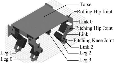
Fig.1 Three dimensional prototype of LittleCalf
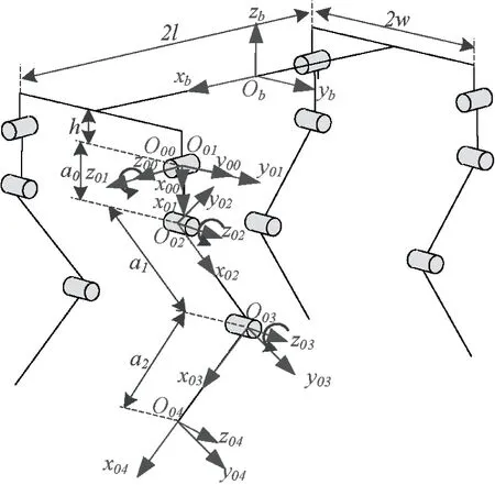
Fig.2 Joints topology and D-H coordinate frames of LittleCalf
1.2 Control system
Servo motor MG995 is chosen as the actuator of the robot’s joint.This kind of servo motor has the advantage of high torque:short response time:light weight and easy to control.A high capacity lithium-ion battery is fixed under the torso to supply the whole system.Onboard control circuit is based on the single chip computer (SCM) MC9S12XS128 from Freescale:coupled with the power management module:motor drive module:environmental perception module (IMU to detect attitude of the torso:and foot switch to detect whether the foot touches the ground) and communication module.
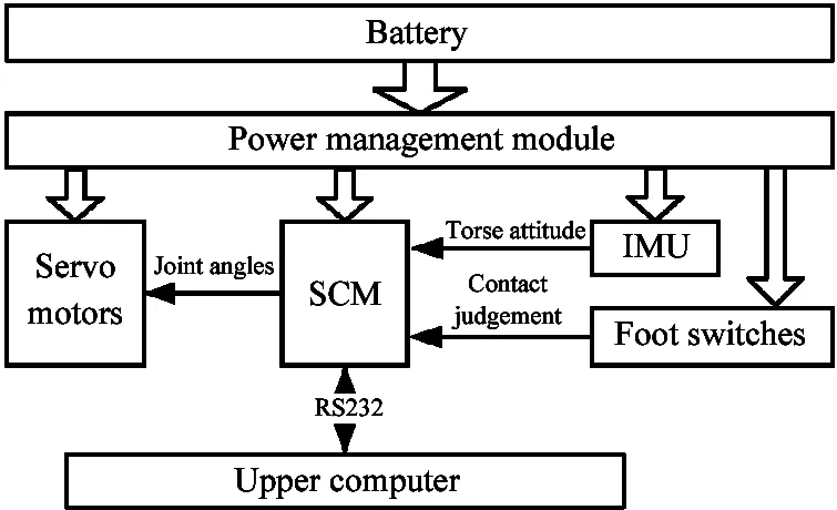
Fig.3 Block diagram of control system
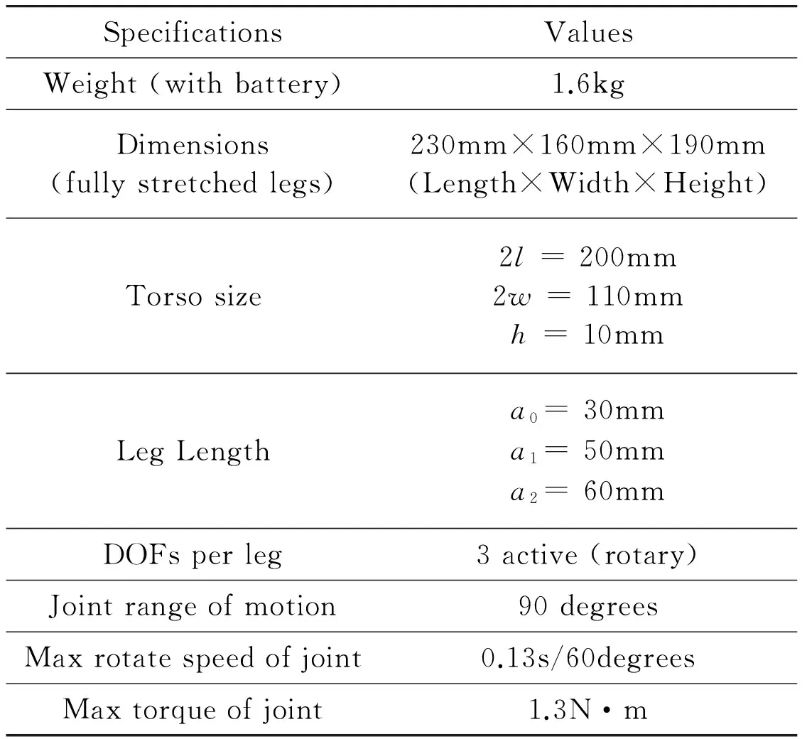
SpecificationsValuesWeight(withbattery)1.6kgDimensions(fullystretchedlegs)230mm×160mm×190mm(Length×Width×Height)Torsosize2l=200mm2w=110mmh=10mmLegLengtha0=30mma1=50mma2=60mmDOFsperleg3active(rotary)Jointrangeofmotion90degreesMaxrotatespeedofjoint0.13s/60degreesMaxtorqueofjoint1.3N·m
Block diagram of the control system is shown in Fig.3.Table 1 shows the major technical specifications of LittleCalf.
2 Kinematic equations
2.1 D-H coordinate frames and link parameters
As shown in Fig.2:the origin of the body fixed coordinate frame {Ob} locates in the geometric center of the torso:andxbpoints to the forward direction:zbpoints opposite to the gravity direction.Andybaxis is confirmed using right-hand rule.There are four coordinate frames noted as {Oi0}(i=0:1:2:3) fixed on the four corners of the torso respectively.The coordinate frames fixed on linkknoted as {Oik} of four legs are established according to D-H rules[14].Fig.2 shows coordinate frames of leg 0.Coordinate frames of the other three legs are establish accordingly.Since the mechanical configurations of the four legs are extremely identical:the coordinate frames and transformation matrices of four legs are identical too.The only difference is the posture between fore legs and rear legs.The link parameters of LittleCalf are illustrated in Fig.2 and listed in Table 2.

Table 2 Link parameters of LittleCalf
2.2 Forward kinematic equations
Since the four legs of LittleCalf have the same D-H coordinate frames and link parameters:they have same forward kinematic equations from {Oi4} to {Oi0}.The transformations from {Oi0} to {Ob} for four legs can be expressed by the following transformation matrix with different values ofδandλ:
(1)
wherel:wandhare geometry parameters of the torso specified in Fig.2:δandλare sign flags which are defined as

(2)

(3)
The coordinates of one foot with respect to {Oi0} corresponding to the same leg can be obtained easily through homogeneous transformations.It is given by
(4)
whereck=cosθik:sk=sinθik:s12=sin(θi1+θi2):c12=cos(θi1+θi2).
Eq.(4) is the forward kinematic equation for four legs.The coordinates of four feet in {Oi0} can be solved respectively from it.Furthermore:the coordinates of four feet in {Ob} can be obtained by premultiplying transformation matrixi0Ti4withbTi0respectively.And the coordinate {xi:yi:zi}Tof one foot in {Ob} can be gained by
(5)
And the jacobian matrix for the leg is
(6)
2.3 Inverse kinematic equations
The inverse kinematic analysis is necessary for motion planning and controlling.Although the forward kinematic equations for four legs from {Oi4} to {Oi0} are identical:the inverse kinematic equations of joint variablesθi1andθi2are not the same since the fore legs and the rear legs are indifferent postures.The feet of LittleCalf are simplified to four points in this paper.If given the coordinates of one foot with {xi:yi:zi}Tin {Ob}:the corresponding joint variablesθikcan be resolved from the inverse kinematic equations.Moreover:its coordinates in other frames can be obtained by forward and inverse homogenous transformation.Ref.[18] gives the detailed derivation for inverse kinematic equations of a quadruped robot.This study gives the results directly as
(7)
Among them
(8)
(9)
2.4 Workspace of the foot
Given the mechanical parameters of LittleCalf and rotation range of the joints:using Eq.(5):the foot workspaces of the robot could be got.The workspace can help us in the motion planning of each foot.Take leg 0 as example:the foot workspace could be got show in Fig.4.And the trajectory of left front foot in this workspace could be planned.
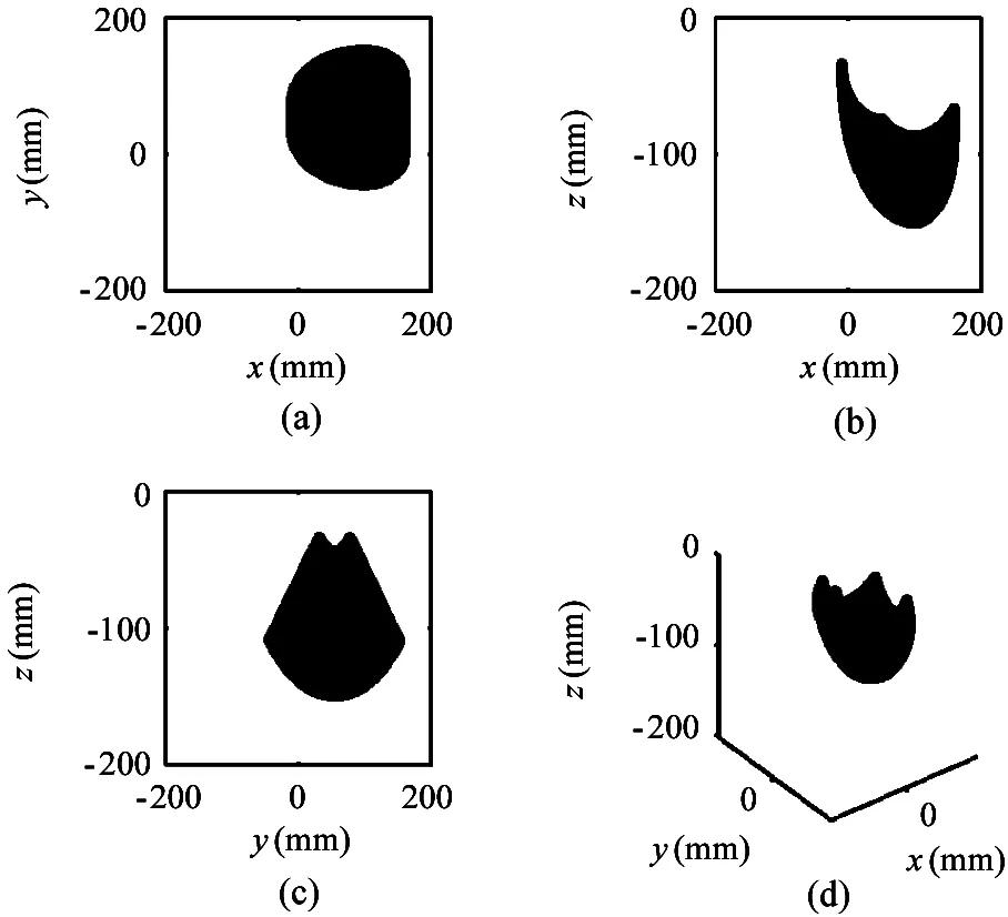
Fig.4 Workspace of the foot of leg 0 with respect to torso fixed frame {Ob}:(a):(b) and (c) show the projection of the workspace on thex-yplane:x-zplane andy-zplane:(d) shows foot workspace in 3D view
Point {x0:ini:y0:ini:z0:ini}T={100:55:-130}Tis chosen as the initial foot position of leg 0:since there are rather big space for the foot to move near this point.Initial position of the other three feet are confirmed similarly.
3 Control torso attitude
In nature:quadruped animals employ different kinds of gaits to move.The trotting is the kind of gait that the diagonal legs move together:which exhibits good energy efficiency over a wide range of running speed:showing no significant pitch or roll motion during each stride and therefore is often seen in nature[19].Many famous quadruped robots such as HyQ[20]:BigDog[4]:LS3[5]:have selected trotting gait as their primary gait.Thus this work majors in controlling the trotting gait of the robot.
The trot is a kind of dynamic gait and in support phase the diagonal standing legs synchronously support the body.Thus the torso would easily rotate about the body diagonal line in trotting.And attention must be paid on controlling the torso attitude.
The concept of the virtual leg is invoked to simplify the control algorithms of the quadruped running.Since the trotting gait pairs their diagonal legs:and the diagonal feet will move almost the same way from their hips and exert equal forces on the ground:their behavior is precisely equivalent to the behavior of the virtual leg[3,21].
Fig.5 shows the correspondences between the trot gait and the equivalent virtual model.The motion of the trotting quadruped robot can be simplified to a virtual biped one and further to the one with single leg.Then the motion of one-leg model are furthers simplified to the two-dimensional plane.Fig.6 shows the planar graph of the simplified robot model and the coordinate system built.All the model variables in Fig.6 are defined in Table 3.
Since LittleCalf is a position-controlled robot:the joint torques can not be directly regulated to control the torso attitude.But the foot velocity can be programmed so as to make the hip exert equivalent torque.
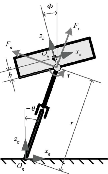
Fig.6 Planar graph of the simplified robot model
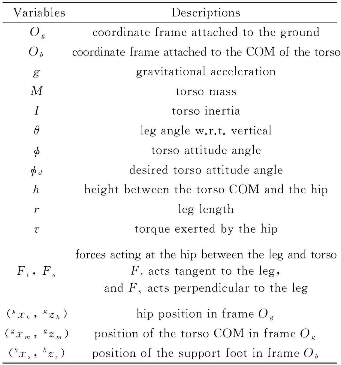
VariablesDescriptionsOgcoordinateframeattachedtothegroundObcoordinateframeattachedtotheCOMofthetorsoggravitationalaccelerationMtorsomassItorsoinertiaθleganglew.r.t.verticalϕtorsoattitudeangleϕddesiredtorsoattitudeanglehheightbetweenthetorsoCOMandthehiprleglengthτtorqueexertedbythehipFt,FnforcesactingatthehipbetweenthelegandtorsoFtactstangenttotheleg,andFnactsperpendiculartotheleg(gxh,gzh)hippositioninframeOg(gxm,gzm)positionofthetorsoCOMinframeOg(bxs,bzs)positionofthesupportfootinframeOb
This model makes the simplifying assumptions of negligible frictional losses:zero leg mass:and a total center of mass (COM) located at the torso.Dynamic equations for the model are derived as
(10)
(11)

(12)
(13)
(14)
(15)

(16)
τ=-Fnr
(17)
Assume the controller could maintain the robot torso relatively level andφis closed to 0.The simplification that sinφ≈0:cosφ≈1:sin(φ-θ)≈sin(-θ) and cos(φ-θ)≈cos(-θ) can be got.Then Eqs(12) (13) and (16) can translate to
(18)
(19)
(20)
(21)

(22)
Since Eq.(22) is a nonlinear differential equation:it is difficult to obtain the universal analytic solutions.But the qualitative analysis of it can be taken.Integrate Eq.(22) with respect to time:yields:

(23)
where subscribe 0 indicates the initial value:and
(24)
(25)
Note thatAis always positive.So if given the desired torso attitude angleφdand


(26)
Under the assumption of negligible frictional losses:the feet do not move with respect to the ground during the stance phase and the backward motion of a support foot with respect to the body coordinate is equal to the forward motion of the body with respect to the ground.That is


(27)

4 Trotting controller
The control of the rectilinear motion of the robot is divided into the support phase control and flight phase control.Both of them are designed based on the virtual leg model and later on translated to the quadruped model.Then the yaw controller is involved to modify the foot position and enable the robot to rotate around the yaw axis.
For simplicity:all of the following coordinates in this paper are defined in the body frame unless noted otherwise.
4.1 Support Phase
For the foot in the support phase:thezcoordinate of the foot should remain unchanged as mentioned before.Meanwhile thexcoordinate would customarily be function of the starting point:the velocity and time.See
(28)
where
xsandzsare the coordinates of the support foot.

xs0is thexcoordinate of the starting point:i.e.:the vertical position of the support foot at time 0.
tis the current time.
z0is the initial vertical coordinate of support foot.


(29)
And the foot trajectory of the support phase will change to
(30)
4.2 Flight Phase
Motion trajectory of the flight foot should go through the lift-off point (xf0:z0):and the touch-down point (xfT:z0).Obviously the lift-off point is the final status of the last support phase:and the touch-down point will be the initial status of the next support phase.

(31)
In order to minimize the contact forces between ground and the foot:it is generally considered that the foot trajectory should meet the demand that the vertical velocity becomes zero at the time of touch-down:lift-off and maximum foot height.
In addition:it is hoped that there are no steps with the position curve and velocity curve of the foot.According to Eq.(29):the velocity of the support foot (also velocity of the torso) would not be a constant value and the coordinate of the foot while lifting off would be variable.Thus the foot trajectory of the flight phase should be state based.
The requirements for the flight phase trajectory can be summarized as
(32)
where
xfandzfare the coordinates of the flight foot.
Hfindicates the step height.
Tfis the length of the flight phase time.For trotting gait with duty factorβ=0.5:Tf=Ts.
Thus the equations for the flight phase foot trajectory are

(33)
(34)
The next step is to transform the virtual leg model back to the quadruped robot.In the derivation mentioned above trajectories that lie in thex-zplane of the virtual leg model are generated:but this can be easily extended to any orientation and eventually to the quadruped robot.Equations for the foot of the real quadruped robot are given in Appendix A.
4.3 Yaw Control
The control algorithm discussed earlier can drive the robot to move in longitudinal or lateral directions:while yaw control would enable it to spin or make turns.
In our controller:foot placement is used to generate a yaw motion of the robot.As shown in Fig.7:if the feet are positioned to rotate the line connecting the feet about the center of mass:the robot body will spin around the yaw axis (zbaxis in Fig.2).The resulting couple is used to manipulate the yaw orientation of the quadruped without disturbing its rectilinear motions.Coordinates for the feet will be
(35)
where
(xi:yi:zi) are the coordinates of footiin {Ob} programmed for the rectilinear motions.
(Xi,Yi,Zi) are the modified coordinates of footi.
ψ(t) is the angle between the line through the hips and the line through the diagonal feet:as shown in Fig.7.
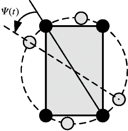
Fig.7 Control of turning about the yaw axis.The diagram shows the quadruped viewed from above:indicating how the placement of the feet can be used to generate a spinning motion of the robot.The filled circles indicate the location of the hips.Tile open circles indicate the placement of the feet
Similar to the previous part:ψ(t) of the support feet and flight feet are programmed separately with the desired yaw rate.For the support feet:
(36)
And for the flight feet:

(37)

BlockdiagramofthetrottingcontrollerisshowninFig.8.
5 Experiments
Forthesakeofverifyingkinematicequationsandtheperformanceofthetrottingcontroller:andgettingsomeimportantparameters:experimentsareconductedbothinsimulationandontherealrobot.ThemobileroboticssimulatesoftwareWebotsisusedforthesimulationtests.ThissectiondemonstratessuccessfultrottinginsimulationandontherealLittleCalfrobotwiththe same controller:while it also shows how the system responds to unexpected perturbations in simulation.
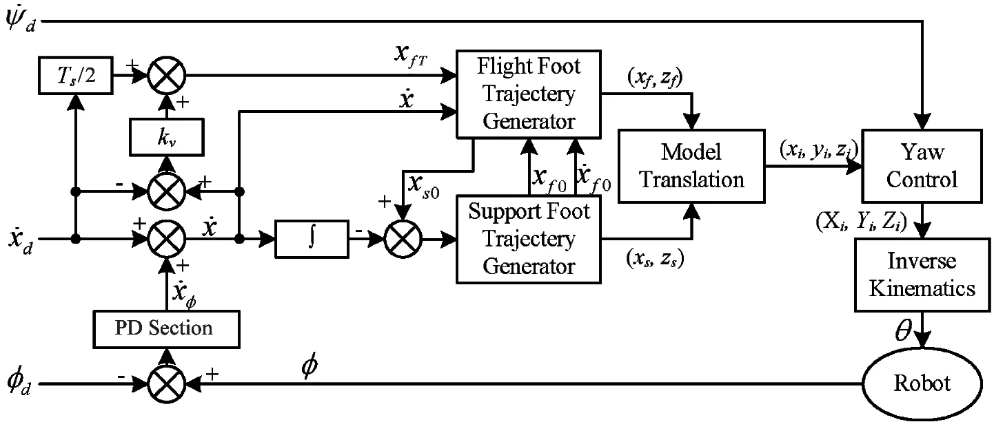
Fig.8 Block diagram of the trotting controller
Some parameters used in the simulation and the physical prototype test are listed in Appendix B.
5.1 Trotting in simulation
The initial implementation and testing cycle have been performed in simulation.There it is able to test and tune a number of different controller parameter sets and obtain exhaustive data about the motions.
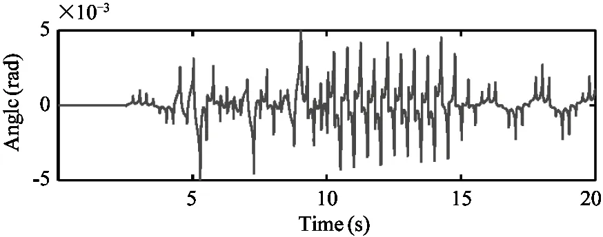
The trotting controller is capable of trotting in place where it maintains the body attitude very close to zero.The desired forward velocity of the robot is ramped up to 0.05m/s and then to 0.1m/s and finally ramp down to zero.In Fig.10:a run of this procedure is presented.Fig.9(a) and Fig.9(b) present the robot velocity while Fig.9(c) and Fig.9(d) show the torso attitude throughout this simulation trial.Example snapshots of the robot trotting in simulation are available in Fig.10.And the leg motions during the 0.1m/s trot in world frame are plotted by stick sequence for two gait cycles in Fig.11.
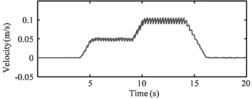
(a) Forward velocity of the robot torso through the simulation run
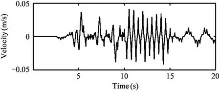
(b) Lateral velocity of the robot torso through the simulation run
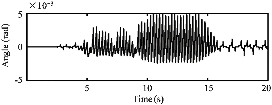
(c) Roll angle of the robot torso through the simulation run
(d) Pitch angle of the robot torso through the simulation run
Fig.9 Plots of the velocity and attitude of the robot throughout the simulation run.The robot was trotting at place at first and then the desired forward velocity ramped up to 0.05m/s and then to 0.1m/s and finally ramped down to zero
Fig.10 Snapshots showing the robot trotting in simulation.From left to right:trotting at a forward velocity of 0m/s:at 0.05m/s and 0.1m/s
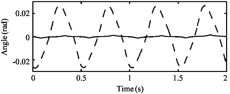
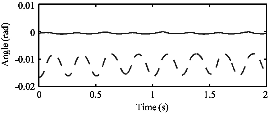
Moreover:to test the superiority of the controller compared with traditional position-controlled gait planning method:the composite cycloid foot trajectory in Ref.[1] on our robot is applied.Fig.12 shows the torso attitude of the robot while the robot trotting forward with velocity of 0.1m/s using the composite cycloid foot trajectory in Ref.[1] as well as using the trotting controller proposed in this paper.Obviously the controller could maintain the body attitude much more close to zero.

Fig.11 Stick figure sequence of leg 0 (right) and leg 2 (left) for two gait cycles (from left to right):described in sagittal plane of world frame.The desired forward speed of the robot is 0.1 m/s
(a) Roll angles of the robot torso
(b) Pitch angles of the robot torso
Fig.12 Comparison of the torso attitude angles collected in the simulator while the robot trotting with the composite cycloid foot trajectory and with the trotting controller.Dashed lines:trotting with the composite cycloid foot trajectory.Solid line:trotting with the trotting controller.The desired forward velocity are all set to 0.1m/s
5.2 Path tracking test
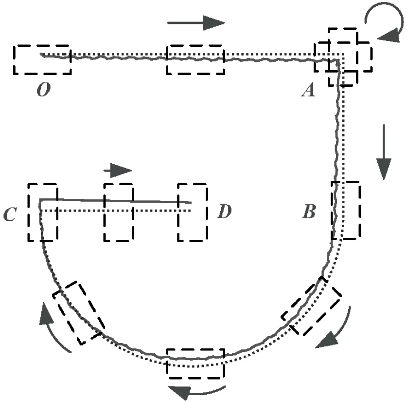
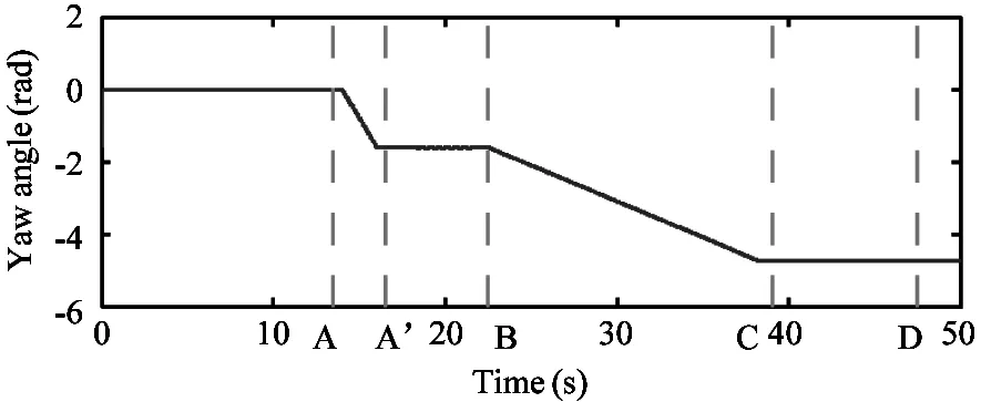
If the robot has the ability to actively move forward or sideward:spin or make turns:it can effectively avoid large obstacles in front or track a complex path.In the simulation:the robot is dictated to track a desired path as shown in Fig.13(a) (dashed line).The starting point isOand the robot moves forward to pointA.AtAit spins for 90° to right and then move forward to pointB.After that:the robot is dictated to make a right turn and draw a semicircle path to pointC.Finally it moves right-sideward and arrives atD.
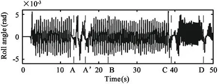
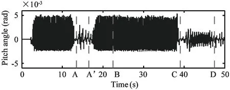
The simulation results for this task are shown in Fig.13.The solid line in Fig.13(a) indicates the desired and actual trajectory of the robot’s COM.It seems that the robot tracks the desired path quite well.Fig.13(b):Fig.13(c) and Fig.13(d) show the roll:pitch and yaw angles of the torso during the motion.The vertical dashed lines labelledA:B:CandDindicate the moments when the robot arrives at pointA:B:CandDof the path.And the dates between timeAandA’ show the spinning motion of the robot at pointA.The snapshots of this simulation are exhibited in Fig.14.
(a) Desired and actual path of the robot
(b) Roll angle of the robot torso
(c) Pitch angle of the robot torso
(d) Yaw angle of the robot torso
Fig.13 Simulation results of path tracking test.In (a):the solid and dashed lines indicate the actual and desired paths:respectively.(b)(c)(d) shows the torso attitude angles and the vertical dashed lines indicate the moments when the robot arrives at the corresponding points
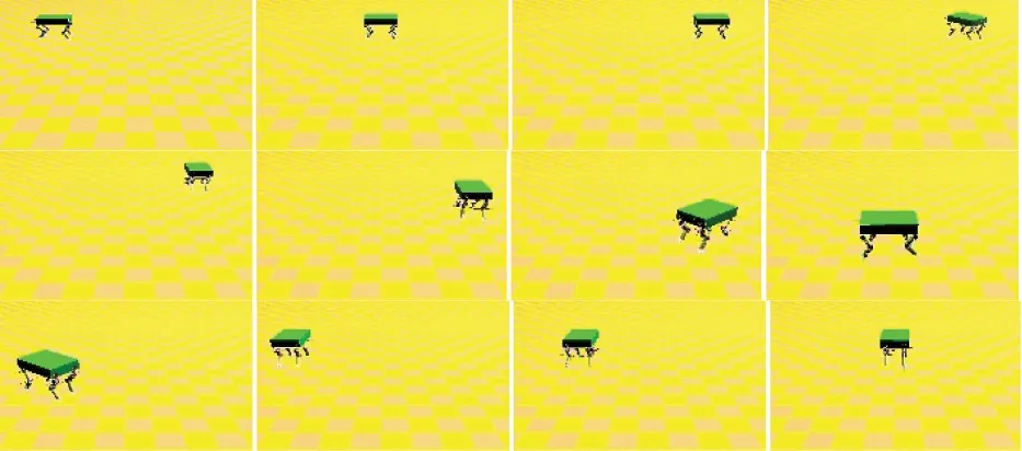
Fig.14 Snapshots showing the path tracking simulation
5.3 Impact recovery
A showcase of the controller robustness is the ability to recover from unexpected perturbations.Due to the morphology of the robot:perturbations along the coronal plane are much harder to accommodate[22].the response of the controller is tested while trotting in place and while trotting at a constant velocity.
Unexpected impacts are exerted on the broadside of the robot by a pendulum bob in simulation.The impulse acting on the robot’s torso is 0.3kg·m/s.When trotting in place and when trotting in the specified velocity range the robot can successfully recover from perturbations.Fig.15 shows how the controller responds to the impact by presenting the attitude and the velocity of the robot body as it is impacted laterally by the pendulum bob:and how the disturbances are dissipated.
5.4 Test on LittleCalf
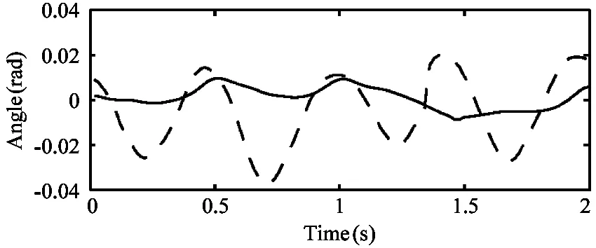
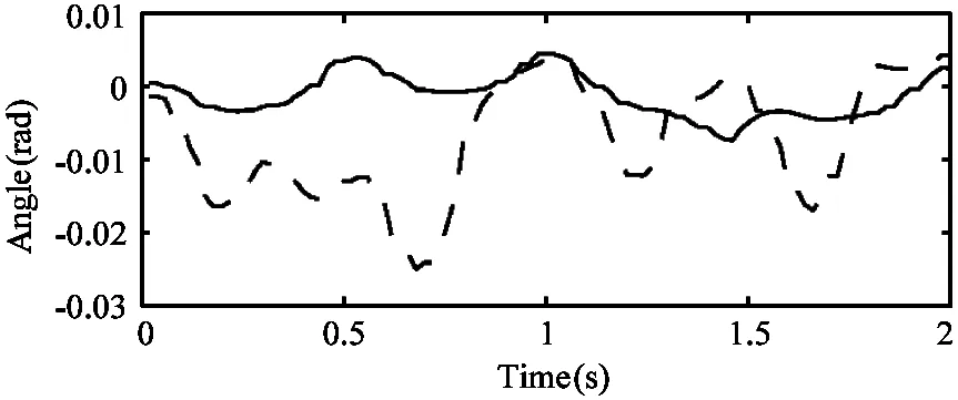
The trotting controller is tested on the real quadruped robot with similar success including experiment with the robot trotting in place:trotting forward and backward.Fig.17 shows a photo of the LittleCalf robot trotting forward with the forward velocity of 0.1m/s.In the same way:the composite cycloid foot trajectory proposed in Ref.[1] is also applied on LittleCalf as comparison.The pitch and roll angles of the torso in these experiments are presented in Fig.18.And similarly:LittleCalf also demonstrates the ability of omni-directional moving and the path tracking test is shown in Fig.19.
Snapshots from this test are presented in Fig.16.
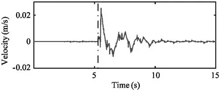
(a) Forward velocity of the robot torso through the lateral impact test
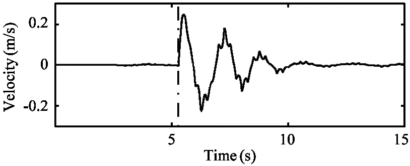
(b) Lateral velocity of the robot torso through the lateral impact test
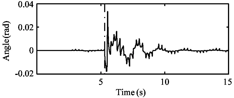
(c) Roll angle of the robot torso through the lateral impact test
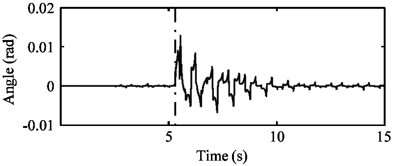
(d) Pitch angle of the robot torso through the lateral impact test
Fig.15 Plots of the velocity and attitude of the robot collected from the lateral impact test.Vertical dashed line shows the time that the robot torso being impacted laterally by the pendulum bob.The bob is 0.15kg weight and moves at speed of 2m/s before knocking on the robot
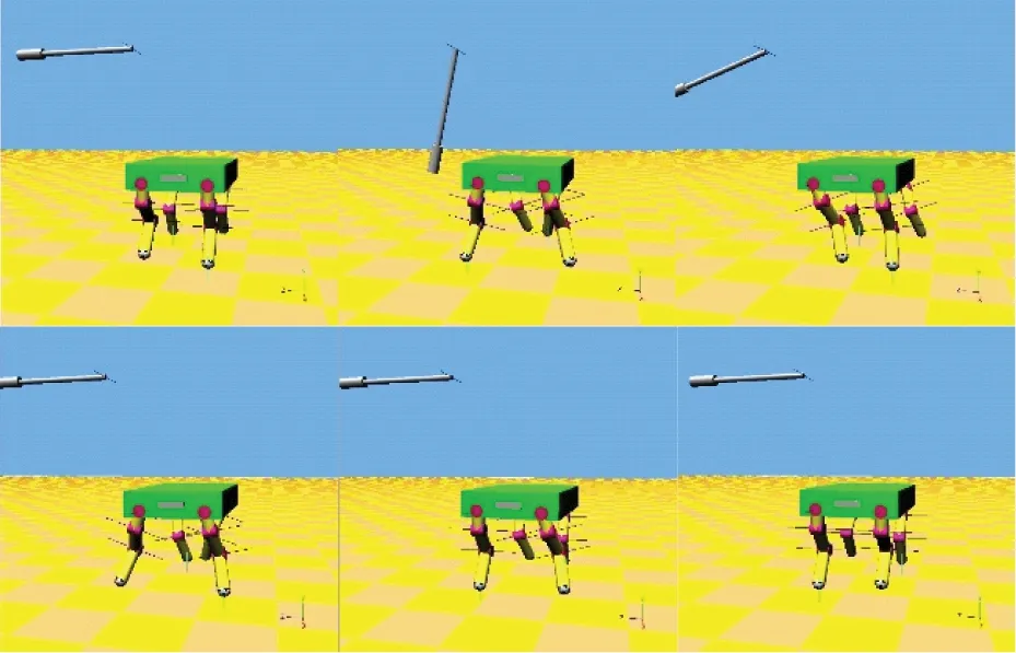
Fig.16 Snapshots showing the impact recovery of the quadruped robot

Fig.17 Photo of the LittleCalf trotting with forward velocity of 0.1m/s
(a) Roll angles of the robot torso
(b) Pitch angles of the robot torso
Fig.18 Comparison of the torso attitude angles collected through LittleCalf while the robot trotting with the composite cycloid foot trajectory and with the trotting controller.Dashed lines:trotting with the composite cycloid foot trajectory.Solid line:trotting with the trotting controller.The desired forward velocity are all set to 0.1m/s
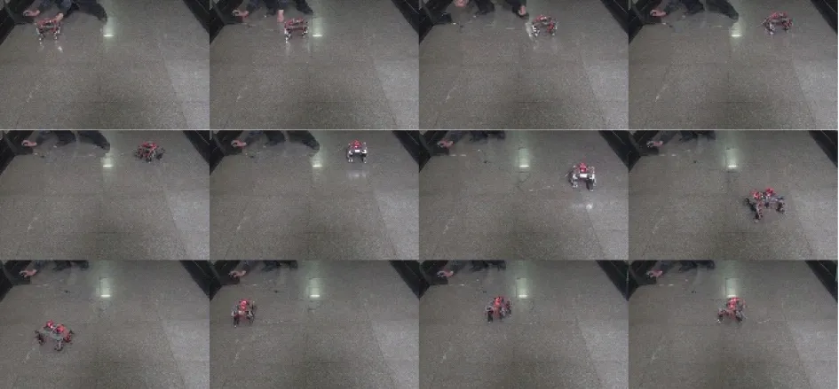
Fig.19 Snapshots showing the path tracking test on LittleCalf
Objectively speaking:the test done on LittleCalf is less than perfect compared to that in simulation on account of the limitations of the hardware platform.That is the shortcoming of position control which requires high motion precision and accurate sensor values[23].And in simulation it is possible to decouple the control laws from the limitations of specific hardware platforms.Nonetheless:the controller is still quite effective on LittleCalf and shows superiority in maintaining the torso attitude.
6 Conclusion
Based on the actuation mode and sensors of the robot LittleCalf:this paper elaborates a trotting controller for the position controlled quadruped robot:which utilizes the torso attitude control:moving velocity control and yaw control.It has shown how the controller is organized and how the different tasks are implemented.Main advantage of the controller is that the complex dynamic calculation of the robot and complicated force control are avoided yet the robot could move steadily and stably.How this trotting controller is able to trot at varying speeds and varying directions and how it can robustly dissipate unexpected perturbations in simulation are presented.Moreover:Effectiveness of the trotting controller is also verified by experiments on LittleCalf.
However:every coin has two sides.Shortcomings of our trotting controller are quite obvious:which requires high motion precision and accurate attitude sensor values.And collision between the feet and the ground may be strong since it does not employ force control thus this method may not be suitable to be directly applied to some large robots.Nevertheless:our controller is still quite effective in improving the stability and robustness of quadruped trotting and it is believed it will provide a new idea for the quadruped researchers.
In the future work:the controller should be improved so as to enable the robot to move on different types of terrain.There would be more simulations and experiments.
Appendix A:Correspondence between the virtual leg model and the quadruped robot
If legiis in support phase:the coordinate of the foot in {Ob} should be

(38)

(39)
zi,s=zi,ini
(40)
where (xi,ini:yi,ini:zi,ini) indicates the initial point of footideclared in the last part of Section 2.φpandφrare the pitch and roll angles of the robot torso:φpdandφrdare the desired values.
If legiis in flight phase:the coordinate of the foot in in {Ob} is
(41)

(42)
(43)

(44)
(45)
Note that Eqs(38)(39)(40)(42)(44)(45) do not involve the yaw control.
Appendix B:Experiments parameters
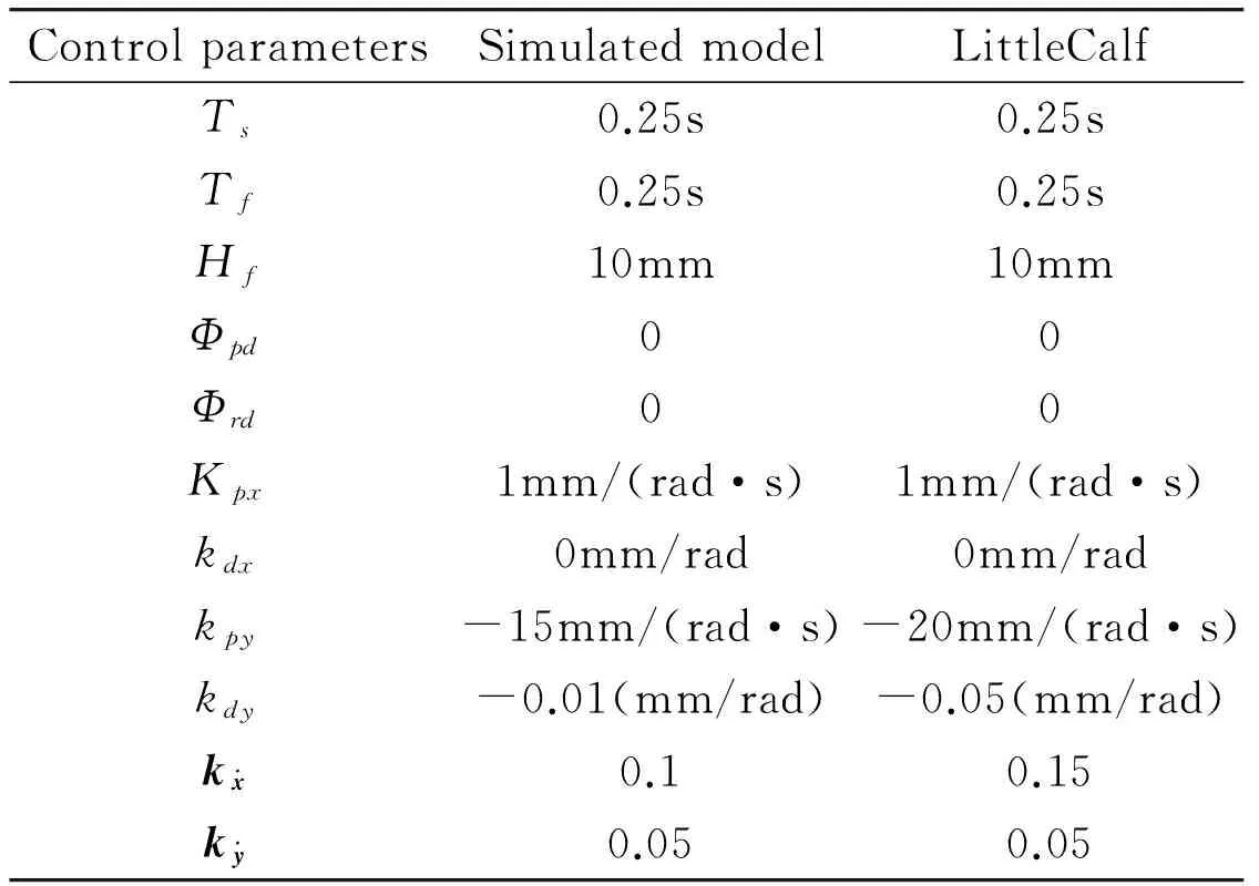
Table 4 Control parameters of the simulated model and LittleCalf
Reference
[1] Rong X:Li Y:Ruan J:et al.Design and simulation for a hydraulic actuated quadruped robot.Journalofmechanicalscienceandtechnology:2012:26(4):1171-1177
[2] Raibert M H.Legged robots that balance.Cambridge:MA:MIT press:1986
[3] Raibert M H.Trotting:pacing and bounding by a quadruped robot.Journalofbiomechanics:1990:23:79-98
[4] Raibert M:Blankespoor K:Nelson G:et al.Bigdog:the rough-terrain quadruped robot.In:Proceedings of the 17th World Congress The International Federation of Automatic Control:Seoul:Korea:2008.10822-10825
[5] Michael K.Meet Boston dynamics’ LS3-the latest robotic war machine.ResearchOnline:2012
[6] Xie H:Ahmadi M:Shang J:et al.An intuitive approach for quadruped robot trotting based on virtual model control.ProceedingsoftheInstitutionofMechanicalEngineers:PartI:JournalofSystemsandControlEngineering:2015:229(4):342-355
[7] Kurazume R:Yoneda K:Hirose S.Feedforward and feedback dynamic trot gait control for quadruped walking vehicle.AutonomousRobots:2002:12(2):157-172
[8] Kalakrishnan M:Buchli J:Pastor P:et al.Learning:planning:and control for quadruped locomotion over challenging terrain.TheInternationalJournalofRoboticsResearch:2011:30(2):236-258
[9] Fukuoka Y:Kimura H:Cohen A H.Adaptive dynamic walking of a quadruped robot on irregular terrain based on biological concepts.TheInternationalJournalofRoboticsResearch:2003:22(3-4):187-202
[10] Barasuol V:Buchli J:Semini C:et al.A reactive controller framework for quadrupedal locomotion on challenging terrain.In:Proceedings of the IEEE International Conference on Robotics and Automation:Karlsruhe:Germany:2013.2554-2561
[11] Gehring C:Coros S:Hutter M:et al.Control of dynamic gaits for a quadrupedal robot.In:Proceedings of the 2013 IEEE International Conference on Robotics and Automation:Karlsruhe:Germany:2013.3287-3292
[12] Yi S.Reliable gait planning and control for miniaturized quadruped robot pet.Mechatronics:2010:20(4):485-495
[13] Kim H:Kang T:Loc V G:et al.Gait planning of quadruped walking and climbing robot for locomotion in 3D environment.In:Proceedings of the IEEE International Conference on Robotics and Automation:Barcelona:Spain:2005.2733-2738
[14] Sakakibara Y:Kan K:Hosoda Y:et al.Foot trajectory for a quadruped walking machine.In:Proceedings of the IEEE International Workshop on Intelligent Robots and Systems:IROS ’90:Ibaraki:Japan:1990.315-322
[15] Dong H:Zhao M:Zhang J:et al.Gait planning of quadruped robot based on third-order spline interpolation.In:Proceedings of the 2006 IEEE/RSJ International Conference on Intelligent Robots and Systems:Beijing:China:2006.5756-5761
[16] Semini C:Tsagarakis N G:Guglielmino E:et al.Design of HyQCa hydraulically and electrically actuated quadruped robot.Proceedings of the Institution of Mechanical Engineers:Part I:Journal of Systems and Control Engineering:2011:831-849
[17] Zhang X:Zheng H:Guan X:et al.A biological inspired quadruped robot:structure and control.In:Proceedings of the IEEE International Conference on Robotics and Biomimetics:Hong Kong:China:2005.387- 392
[18] Rong X:Li Y:Ruan J:et al.Kinematics analysis and simulation of a quadruped robot.AppliedMechanicsandMaterials:2010:26:517-522
[19] Nanua P:Waldron K J.Energy comparison between trot:bound:and gallop using a simple model.Journalofbiomechanicalengineering:1995:117(4):466-473
[20] Semini C.HyQIDesign and development of a hydraulically actuated quadruped robot:[Ph.D dissertation].Genoa:University of Genoa:2010.45-86
[21] Raibert M:Chepponis M:Brown Jr H B.Running on four legs as though they were one.IEEEJournalofRoboticsandAutomation:1986:2(2):70-82
[22] Havoutis I:Semini C:Buchli J:et al.Quadrupedal trotting with active compliance.In:Proceedings of the 2013 IEEE International Conference on Mechatronics:Vicenza:Italy:2013.610-616
[23] Zhang G:Chai H:Rong X:et al.An impact recovery approach for quadruped robot with trotting gait.In:Proceedings of the 2014 IEEE International Conference on Information and Automation:Hailar:China:2014.819-824
Zhang Guoteng:born in 1989.He is currently a PhD student in Shandong University:China.He received his B.S degree from Shandong University in 2007.His research interests include robotics:intelligent control:etc.
10.3772/j.issn.1006-6748.2016.03.012
①Supported by the National Natural Science Foundation of China (No.61233014:61305130):China Postdoctoral Science Foundation (No.2013M541912) and the Shandong Provincial Natural Science Foundation (No.ZR2013FQ003:ZR2013EEM027).
杂志排行
High Technology Letters的其它文章
- Antenna selection based on large-scale fading for distributed MIMO systems①
- Real-time vehicle tracking for traffic monitoring systems①
- A survey of occlusion detection method for visual object①
- Concurrent processes scheduling with scarce resources in small and medium enterprises①
- Real-time video compression system design and hardware implementation based on multiple ADV212①
- MapReduce based computation of the diffusion method in recommender systems①
