Bionic jumping dynamics of the musculoskeletal leg mechanism for quadruped robots①
2016-12-05LeiJingtao雷静桃WuJiandong
Lei Jingtao(雷静桃), Wu Jiandong
(School of Mechatronic Engineering and Automation, Shanghai University, Shanghai 200072, P.R.China)
Bionic jumping dynamics of the musculoskeletal leg mechanism for quadruped robots①
Lei Jingtao(雷静桃)②, Wu Jiandong
(School of Mechatronic Engineering and Automation, Shanghai University, Shanghai 200072, P.R.China)
As the pneumatic artificial muscle (PAM) has flexibility properties similar to biological muscle which is widely used in robotics as one kind of actuators, the bionic mechanism driven by PAMs becomes a hot spot in robotics. In this paper, a kind of musculoskeletal leg mechanism driven by PAMs is presented, which has three joints driven by four PAMs. The jumping movement is divided into three phases. The forward and inverse kinematics of the leg mechanism in different jumping phases is derived. Considering the ground reaction force between feet and environment, the dynamic in different jumping phases is analyzed by Lagrange method, then the relationship between PAM driving force and the joints angular displacement, angular velocity, angular acceleration during one jumping cycle is obtained, which will lay a foundation for the jumping experiment of the musculoskeletal leg mechanism.
musculoskeletal, pneumatic artificial muscle (PAM), jumping, biomechanics, dynamics
0 Introduction
From the biological movement, the bionic running or jumping movement style is advantaged in the mobility and environmental suitability. The bionic robot is one of the important researching directions, and the bionic jumping or running robots have been paid more attention in recent years[1].
The jumping movement is characterized by large instantaneous forces and short duration. For example, the duration time for vertical jumping is about 2s. Musculoskeletal system driven by PAMs can achieve jumping movement. The pneumatic muscle allows dynamic and agile movements for a robot with the property of light-weight and large amount of energy converted in short period of motion.
PAMs have been widely used in various robotic systems[2]. The muscles were adopted to actuate the robot because of high power to weight ratio and properties similar to biological muscles.
In the musculoskeletal system, PAM is widely adopted as an actuator for walking robots instead of the electric servomotor. PAM is similar to biological muscles in shape and working principles, which can meet the flexibility requirements. PAMs have many desirable characteristics, such as flexibility similar to biological muscles, high power to weight ratio, high power to volume ratio, and inherent compliance and have therefore been widely used in various robotic systems[2].
The musculoskeletal system gives animals the ability to move in a huge variety of environments. Some researchers have paid more attention to the musculoskeletal legged system. Niiyama presented a pneumatically actuated bipedal robot “Mowgli”, whose artificial musculoskeletal system consists of six McKibben pneumatic muscle actuators. The robot can achieve vertical jumping with disturbance. Mowgli can reach jump heights of more than 50% of its body height and can land softly[2]. A kind of bipedal running robot using musculoskeletal system is presented. The configuration of the muscles is compatible with the human. The muscle activition of the musculoskeletal leg is determined by measuring the muscle activity and kinetic data of human[3]. Yamada developed a quadruped robot, which was designed by simulating the musculoskeletal system of quadruped animal. Different muscle configurations were analyzed. Some experiments were conducted to investigate emergent phenomena[4-6]. A kind of quadruped robot driven by PAMs is presented. The force characteristic is studied. The PAMs are controlled using pulse-width modulation with closed-loop position feedback[7,8]. Hosoda[9]developed one kind of biped robot, which has a bio-mimetic muscular-skeleton system driven by McKibben PAMs to realize stable bouncing. Kenichi[10]developed a kind of quadruped robot with the minimalistic and light-weight body for achieving fast locomotion. The McKibben PAMs have been used as actuators to provide high frequency and wide stride motion, and to avoid problems of overheating. A frog-inspired hopping leg driven by PAMs is presented, and the kinematic analysis is performed in landing and airboren phase respectively. Vertical jumping simulation is performed[11,12].
A kind of musculoskeletal leg mechanism inspired by the running or jumping movement of animal is developed, which has 3 DOF driven by four PAMs for running or jumping quadruped robot. The jumping movement is divided into three phases, which are takeoff phase, jumping phase and landing phase. The forward and inverse kinematics of the musculoskeletal leg mechanism is derived. Considering the contact force between foot and environment, the dynamic is derived. The relationship between the PAM driving force and the joint angular displacement, angular velocity, angular acceleration is obtained. Meanwhile, the PAM driving force can be determined.
1 Quadruped robot with musculoskeletal leg mechanism
The quadruped robot system is designed by inspiring from the quadruped animals, such as, dog, cheetah, which is composed of one bionic flexible body and four legs, as shown in Fig.1.

Fig.1 Quadruped robot
PAM plays an important role in realizing coordinated movement of joints. There are four PAMs in the leg mechanism. PAM can imitate the behavior of biological muscle. The musculoskeletal leg mechanism is designed as shown in Fig.2. The leg mechanism has three rotational joints, which are side-swing hip joint, walking hip joint and knee joint. The side-swing hip joint is driven by one PAM, the walking hip joint is driven by one PAM, and the knee joint is driven by two PAMs[13].
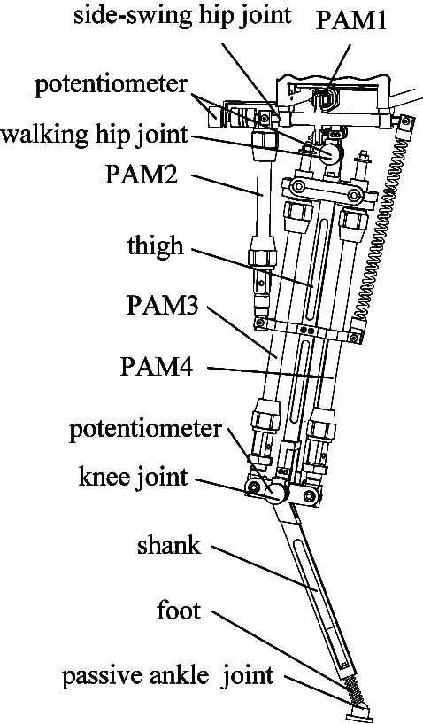
Fig.2 Musculoskeletal leg mechanism
The movable range of each joint is designed similarly to those of quadruped creatures. The movable range of the side-swing hip joint is 15°, the walking hip joint is 10° and the knee joint is 60°, respectively.
The hip joint’s flexion/extension is driven by two muscles. The hip joint can achieve side-swing and forward/backward-swing. The knee joint’s flexion/extension is driven by two muscles, in order to increase the rotate range of the knee joint. PAM has the characteristics: tending to contract, and hard to elongate. This characteristic is considered to arrange the PAMs for driving the knee joint. So the mechanical stretch structure is designed at the upper end of the PAM, which can compensate the lack of the PAM elongation.
2 Kinematic of leg mechanism
Kinematic is to determine the relationship between the joint varieties and feet pose. One jumping cycle is divided into three phase, which are takeoff phase, jumping phase and landing phase, as shown in Fig.3.

Fig.3 One jumping cycle
2.1 Takeoff phase or landing phase
During the takeoff phase and landing phase, because the movement of leg mechanism is the same, the kinematic of leg mechanism in takeoff phase and land phase can be analyzed with the same method.
When the robot is in turning gait or spinning gait, the side-swing hip joint is mainly used to assist the body to achieve turning movement, so it needs not to be considered in the jumping kinematics analysis.
During the takeoff phase and landing phase, if there is not relative slippage between the feet and the ground, the movement of foot relative to the ground can be looked as passive rotary joint. The fixed reference frame system is located at the foot-end, and the hip joint is looked as the end of the open chain. The kinematic of the leg mechanism in the takeoff phase is to express the special positions of hip joint relative to the foot-end. The leg mechanism can be looked as an open chain with 3DOF.
The Denavit-Hartenberg method is adopted to analyze the kinematics. The D-H coordinate systems are shown in Fig.4. The coordinate system {0} and {1} are located at foot-end. The coordinate system {2} is located at knee joint, and the coordinate system {3} is located at forward walking hip joint.
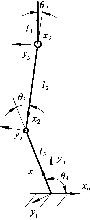
Fig.4 Coordinate frames of leg in the takeoff phase
According to the D-H coordinate systems, the link parameters can be determined as shown in Table 1.

Table 1 D-H parameters of the leg mechanism
The position and orientation of frame {3} with respect to frame {0} can be described by the 4×4 homogeneous transformation matrix:
(1)
where s2=sinθ2, c2=cosθ2, s4=sinθ4, c4=cosθ4, s34=sin(θ3+θ4), c34=cos(θ3+θ4).

According to the expected trajectory of the frame {3}, the joint angular displacement can be derived by the inverse kinematics as
2.2 Jumping phase
During the airborne jumping phase, the movement of the leg mechanism can be seen as the resultant movement of the motion of the center of mass and links motion relative to the center of mass. So the fixed reference frame system is located at the center of mass, and the D-H coordinate systems are shown in Fig.5.

Fig.5 Coordinate frames of leg in the jumping phase
According to the D-H coordinate systems, the link parameters can be determined shown in Table 2.

Table 2 D-H parameters of the leg mechanism
The position and orientation of the foot-end with respect to frame {0} can be described by a 4×4 homogeneous transformation matrix:
(2)

The joint angular displacement can be derived by the inverse kinematics as follows:
(3)
3 Dynamics of leg mechanism
The dynamics of the robot manipulator driven by PAMs is nonlinear[14]. The jumping dynamics of the musculoskeletal leg mechanism in different phases can be derived by the Lagrange method. As the jumping movement of the leg mechanism is not related with the side-swing hip joint, the leg can be simplified as one 2DOF mechanism.
3.1 Takeoff phase or landing phase
The dynamic of leg in the takeoff phase and the landing phase are the same. There are ground reaction forces between feet and environment, which can provide thrust force to move forward to maintain the posture. The dynamics of the leg can be described in the joint space, which has the following form:
(4)


τFis the vector of contact forces mapped to the joints by transposed Jacobian matrix. The mapping relationship between the contact forces and the joint torques can be expressed by Jacobian matrix:
τF=JT(q)F
(5)
where
The generalized ground reaction force F consists of force component and moment component at the contact point between foot and environment.
where fz=0,nx=0,ny=0
According to the moment principle of leg mechanism, the component of force is
3.2 Jumping phase
(6)

4 PAM driving force
According to the joint driving torque, the needed PAM force for driving joint movement can be derived by the geometric method.
4.1 PAM driving force of walking hip joint
The force analysis of walking hip joint is shown in Fig.6.

Fig.6 Force analysis of the walking hip joint
According to the geometric relationship, there is the static equilibrium equation:
τ2=F2d2-Fkdk
(7)
Since the antagonistic forceFkgenerated by the PAM is smaller, which can be neglected, so the driving force of joint 2 is:
因此,在目前多元化社会思潮和多元化价值观念的影响下,加强医院各科室精神文明建设尤为重要。医务人员只有积极践行社会主义核心价值观,才能避免被非主流的思想观念和价值观念所误导,才能保障我国的医疗卫生事业始终保持正确的价值取向和发展方向,健康稳定可持续发展。
where
4.2 PAM driving force of knee Joint
The force analysis of knee joint is shown in Fig.7.

Fig.7 Force analysis of the knee joint
τ3=F4d4-F3d3
(8)
When PAM4 drives the joint 3, the antagonistic force F3that is generated by PAM3 is smaller, which can be neglected, so driving force of joint 3 is:
5 PAM inner pressure
For the musculoskeletal leg mechanism driven by PAMs, it is necessary to analyze the relationship between the PAM inner pressure and the PAM driving force.
Generally, it is difficult to obtain the precise position control of the robotics system driven by PAMs. In contrast, the force/torque is relatively ease to be controlled by controlling the PAM gas pressure.

(9)
where p is the inner pressure of the PAM.
6 Analysis results
The structural parameters of the musculoskeletal leg mechanism are shown in Table 3.
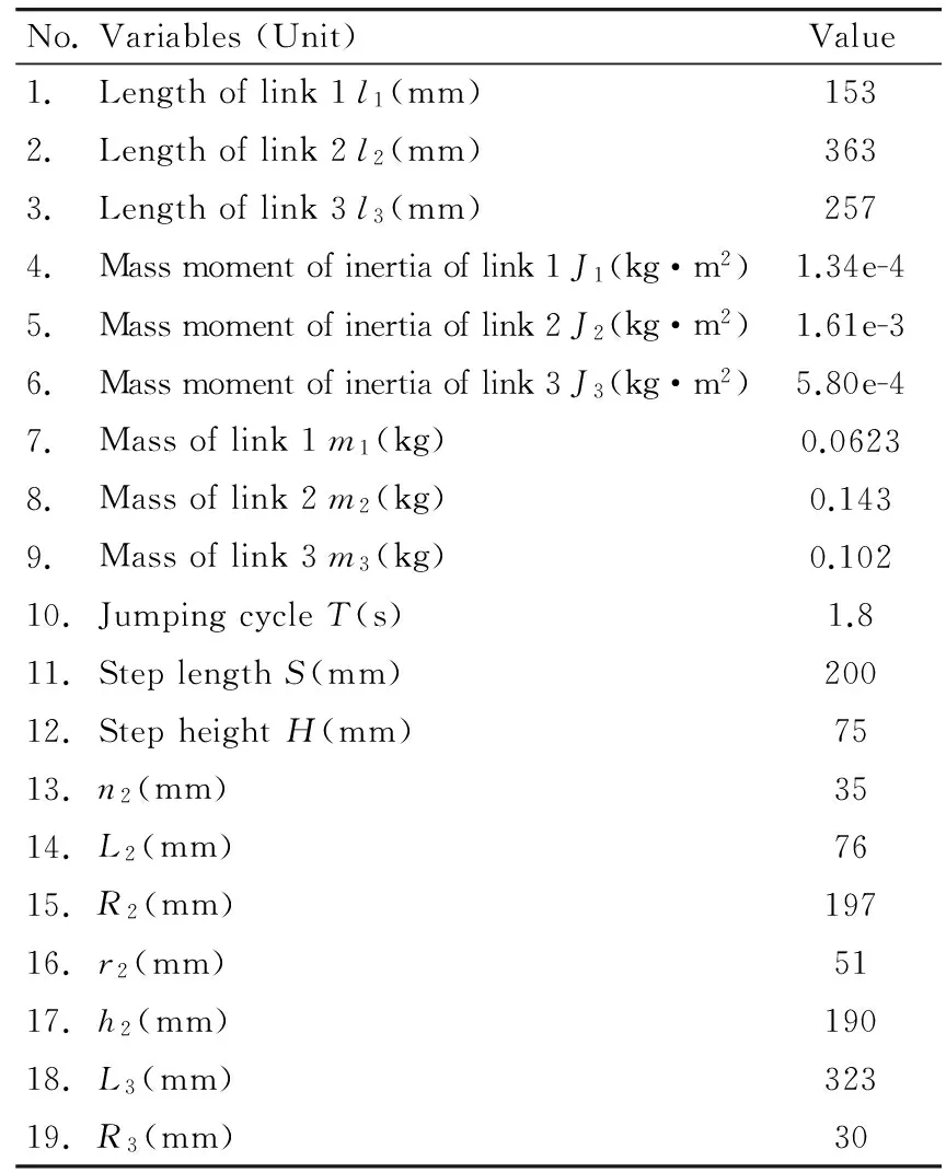
Table 3 Structural and gait parameters
The PAMs from Festo company are selected as actuators, whose maximum shrinkage amount is 20% of the initial length. The structure parameters are shown in Table 4.

Table 4 PAM parameters
One jumping cycle is set as 1.8s. The foot-end trajectory during one jumping cycle is determined as shown in Fig.8(a). Then the joint angular displacement, angular velocity and angular acceleration of the leg mechanism can be calculated as shown in Fig.8(b)~(d).

(a) The foot-end trajectory

(b) Joint angular displacement
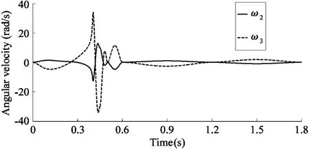

(c) Joint angular velocity
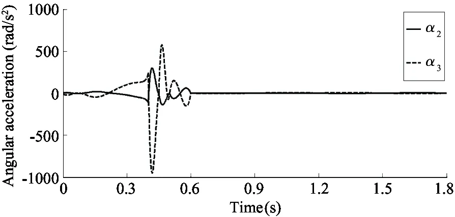
(d) Joint angular acceleration Fig.8 Kinematic results during one jumping cycle
The jumping dynamics results of leg during one cycle can be calculated.
The ground reaction forces are shown in Fig.9(a)~(b). As the jumping is analyzed in this paper, and the jumping is only related to joint 2 and joint 3, so the driving torque of joint 1 is zero. The joint torque is shown in Fig.9(c). The driving forces of PAMs are shown in Fig.9.(d)~(f).

(a) Ground reaction force

(b) Ground reaction torque

(c) Joint torques

(d) PAM2 driving force

(e) PAM3 driving force

(f) PAM4 driving force
Fig.9 Dynamics results during one jumping cycle
7 Conclusions
This paper focuses on the kinematics and dynamics of the musculoskeletal leg mechanism. A kind of musculoskeletal leg mechanism driven by PAMs is presented, which can be implemented to the quadruped robot. The jumping movement is divided into three phases. The kinematics of the leg mechanism in different phases are analyzed to determine the relationship between the joint angular displacement and the foot trajectory. The ground reaction force between feet and environment is considered to derive the dynamics. The future work will focus on the control algorithm and continuous jumping experiments of the musculoskeletal leg mechanism.
[1] Sayama K, Masuta H, Lim Hum-ok. Development of one-legged jumping robot with artificial musculoskeletal system. In: Proceedings of the 9th International Conference on Ubiquitous Robots and Ambient Intelligence, Daejeon, Korea, 2012.608-613
[2] Andrikopoulos G, Nikolakopoulos G, Manesis S, et al. A survey on applications of pneumatic artificial muscles. In: Proceedings of the 19th Mediterranean Conference on Control & Automation, Corfu, Greece, 2011.1439-1446
[3] Niiyama R, Nagakubo A, Kuniyoshi Y. Mowgli: A bipedal jumping and landing robot with an artificial musculoskeletal system . In: Proceedings of the IEEE International Conference on Robotics and Automation, Roma, Italy, 2007. 2546-2551
[4] Niiyama R, Nishikawa S, Kuniyoshi Y. Athlete robot with applied human muscle activation patterns for bipedal running. In: Proceedings of the 10th IEEE-RAS International Conference on Humanoid Robots, Nashville, USA, 2010. 498-503
[5] Yamada Y, Nishikawa S, Shida K, et al. Neural-body coupling for emergent locomotion: A musculoskeletal quadruped robot with spinobulbar model. In: Proceedings of the IEEE/RSJ International Conference on Intelligent Robots and Systems, San Francisco, USA, 2011. 1499-1506
[6] Nishikawa S, Yamada Y, Shida K, et al. Dynamic motions by a quadruped musculoskeletal robot with angle-dependent moment arms. In: Proceedings of the International Workshop on Bio-Inspired Robots, Nantes, France, 2011
[7] Yamada Y, Nishikawa S, Shida K, et al. Emergent locomotion patterns from a quadruped pneumatic musculoskeletal robot with spinobulbar model. In: Proceedings of the International Workshop on Bio-Inspired Robots, Nantes, France, 2011
[8] Aschenbeck K S, Kern N I, Bachmann R J, et al. Design of a quadruped robot driven by air muscles. In: Proceedings of the First IEEE/RAS-EMBS International Conference on Biomedical Robotics and Biomechatronics, Pisa, Italy, 2006. 875-880
[9] Hosoda K, Takayama H, Takuma T, et al. Bouncing monopod with bio-mimetic muscular-skeleton system. In: Proceedings of the IEEE/RSJ International Conference on Intelligent Robots and Systems, Nice, France, 2008. 3083-3088
[10] Kenichi N, Andre R, Alexander S, et al. Development of a minimalistic pneumatic quadruped robot for fast locomotion. In: Proceedings of the IEEE International Conference on Robotics and Biomimetics, Guangzhou, China, 2012. 307-311
[11] Zhang W, Fan J Z, Cai H G. Design of a novel frog-inspired hopping leg. In: Proceedings of the IEEE International Conference on Information and Automation, Shenyang, China. 2012. 277-282
[12] Zhong J, Fan J Z, Zhao J, et al. Kinematic analysis of jumping leg driven by artificial muscles. In: Proceedings of the IEEE International Conference on Mechatronics and Automation, Chengdu, China, 2012.1004-1008
[13] Lei J T, Wu J D, Yu H Y. Analysis on the musculoskeletal leg mechanism driven by PAMs. In: Proceedings of the IEEE International Conference on Mechatronics and Automation, Tianjin, China, 2014.1659-1663
[14] Amato F, Colacino D, Cosentino C, et al. Robust and optimal tracking control for manipulator arm driven by pneumatic muscle actuators. In: Proceedings of the IEEE International Conference on Mechatronics, Vicenza, Italy, 2013. 827-834
[15] Pujana-Arrese A, Mendizabal A, Arenas J, et al. Modelling in modelica and position control of a 1-DoF set-up powered by pneumatic muscles.Mechatronics, 2010, 20(5):535-552
Lei Jingtao, born in 1970. She received her Ph.D degree from Beihang University in 2007. She also received her B.S. and M.S. degrees from Henan University of Science and Technology in 1991 and 1996 respectively. Her research interests include the robot mechanisms and robot modular technology.
10.3772/j.issn.1006-6748.2016.02.002
①Supported by the National Natural Science Foundation of China (No. 51375289), Shanghai Municipal National Natural Science Foundation of China (No.13ZR1415500) and Innovation Fund of Shanghai Education Commission (No.13YZ020).
②To whom correspondence should be addressed. E-mail: jtlei2000@163.comReceived on June 19, 2015
猜你喜欢
杂志排行

High Technology Letters的其它文章
- Identity-based proxy multi-signature applicable to secure E-transaction delegations①
- An optimizing algorithm of static task scheduling problem based on hybrid genetic algorithm①
- Quotient space model based on algebraic structure①
- Learning trendiness from twitter to web: a comparative analysis of microblog and web trending topics①
- Distributed cubature Kalman filter based on observation bootstrap sampling①
- Intelligent outdoor video advertisement recommendation system based on analysis of audiences’ characteristics①