Prismatic and full-waveform joint inversion*
2016-12-02QuYingMingLiZhenChunHuangJianPingandLiJinLi
Qu Ying-Ming, Li Zhen-Chun, Huang Jian-Ping♦, and Li Jin-Li
Prismatic and full-waveform joint inversion*
Qu Ying-Ming1, Li Zhen-Chun1, Huang Jian-Ping♦1, and Li Jin-Li2
Prismatic wave is that it has three reflection paths and two reflection points, one of which is located at the reflection interface and the other is located at the steep dip angle reflection layer, so that contains a lot of the high and steep reflection interface information that primary cannot reach. Prismatic wave field information can be separated by applying Born approximation to traditional reverse time migration profile, and then the prismatic wave is used to update velocity to improve the inversion efficiency for the salt dame flanks and some other high and steep structure. Under the guidance of this idea, a prismatic waveform inversion method is proposed (abbreviated as PWI). PWI has a significant drawback that an iteration time of PWI is more than twice as that of FWI, meanwhile, the full wave field information cannot all be used, for this problem, we propose a joint inversion method to combine prismatic waveform inversion with full waveform inversion. In this method, FWI and PWI are applied alternately to invert the velocity. Model tests suggest that the joint inversion method is less dependence on the high and steep structure information in the initial model and improve high inversion efficiency and accuracy for the model with steep dip angle structure.
prismatic waveform inversion, full waveform inversion, high and steep structure, sag model, Marmousi2 model
Introduction
Traditional reflection exploration cannot image high and steep structures because of the limitations imposed by the observation system and the insufficient illumination of faults, salt dome flanks, and other steeply dipping structures (Hale et al., 1992). Prismatic waves contain a lot of the subsurface information that primary waves do not because they propagate along the subsurface reflection interface and are recorded after the second reflection at the steeply dipping reflection layer. Thus, the prismatic wave information improves the illumination and the imaging of high and steep structures. Presently, prismatic waves are not widely used because (1) seismic processing is primarily based on primary waves and prismatic waves are considered noise (Hawkins, 1994) and (2) the energy of the prismatic waves is less than that of primary waves and thus are covered by the primary waves (Dai, 2012).
Prismatic waves contain significant subsurface information because of the second reflection at steep reflection layers after the reflection at the subsurface interface, where the primary waves cannot reach. Hence,prismatic waves can be used to improve the precision of imaging. Broto and Lailly (2001) used the finitedifference method based on the acoustic equation to model the kinematics of prismatic waves and proposed criteria for identifying them. Cavalca and Lailly (2005) studied the kinematics of two types of prismatic waves and analyzed the generation conditions at vertical flanks (dip angle is equal to 90°), overhanging flanks (dip angle is less than 90°), and steep flanks (dip angle is greater than 90°). Marmalyevskyy et al. (2005) used prismatic waves and the Kirchhoff method to image salt dome flanks. Before using prismatic waves and the Kirchhoff method, the horizontal reflection interfaces need to be extracted. Malcolm et al. (2009) used an iterative one-way wave algorithm to image prismatic and multiple waves stepwise. In this method, every stage is implemented independently and different structures are imaged at different stages, in which prismatic waves are used to improve the illumination of the salt dome flanks. Li et al. (2011) improved the traditional reverse-time migration and proposed a prismatic imaging process for complex salt dome structures. Dai (2012) proposed the prismatic reverse-time migration (RTM) method, which does not need to extract the horizontal reflection layers in advance. However, the calculation time is twice as that of traditional RTM. Based on previous studies, we propose a method of separating prismatic waves when solving the wave equations, which is based on the difference of the Green function between primary and prismatic waves. The method constructs a gradient operator for the waveform inversion of prismatic waves only. Furthermore, considering the dependence on the initial model, the imaging precision for highly steep structures, and the calculation efficiency, the prismatic waveform inversion (PWI) method and the traditional full-waveform inversion (FWI) method (Luo and Schuster, 1990; Krebs et al., 2009; Asnaashari et al., 2013; Ao et al., 2015) are combined to develop a prismatic and full-waveform joint inversion method. The proposed method uses only prismatic waves in the waveform inversion and then uses the full wavefield information to improve the inversion efficiency for high and steep structures. To test the proposed method, we use a sag model and the Marmousi2 model.
Prismatic waveform inversion
The characteristics of prismatic waves are the three main reflection paths and two reflection points that are located at the reflection layers and steep reflection layers, respectively. Prismatic waves can be observed in shot records but are often regarded as noise (Hawkins, 1994). In practice, prismatic waves contain subsurface information that primary waves do not carry.
Prismatic waves can be divided into two types based on their characteristics. The first type is seismic waves that reach the depositional interfaces first and then the salt dome flanks. Finally, the reflection waves are received by the receivers at the surface and are called prism1 or FI. The second type is seismic waves reach the salt dome flanks first and then the depositional interfaces. Finally the reflection waves are received by the receivers at the surface and are called prism2 or FI (Cavalca and Lailly, 2001).
The full-waveform inversion is a method of nonlinear fitting of data, which uses the full wavefield to update the model parameters by minimizing the difference between the observed and model data (Guitton, 2010; Weibull et al., 2012; Dong et al., 2013; Liu et al., 2015). The problem of obtaining the seismic wave velocity using the full-waveform inversion (FWI) is usually defined as solving the minimum of an objective function. In this study, we use the objective function of the L2-norm (Ren, 2011)

where R denotes an operator that sets the wavefield onto the location of the receivers;is the wavefield;anddenote the model and observed data, respectively, xsand xrare the source and receiver, respectively, and t denotes the time.
The variation of the objective function is

After simple deduction, the variation of the objective function is modified as (Ren, 2011)

where v is the velocity; R*denotes extending the data at the receivers to the whole model space; L*denotes the wavefield reverse time back-propagation;denotes extending the data from the receivers to the entire model space;denotes the reversetime continuation of the residual data.
For simplification, we define the data residual as

To obtain the gradient formula of the prismatic waveform inversion, we need to separate the full wavefield u into the first order reflected wavefield u1and the second order prismatic wavefield u2, The full wavefield u can be decomposed into two parts by the follow equation:


Equation (3) can be further transformed to
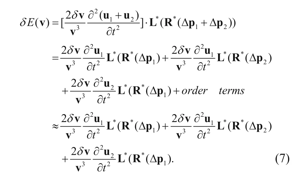
The gradient of the objective function for velocity is
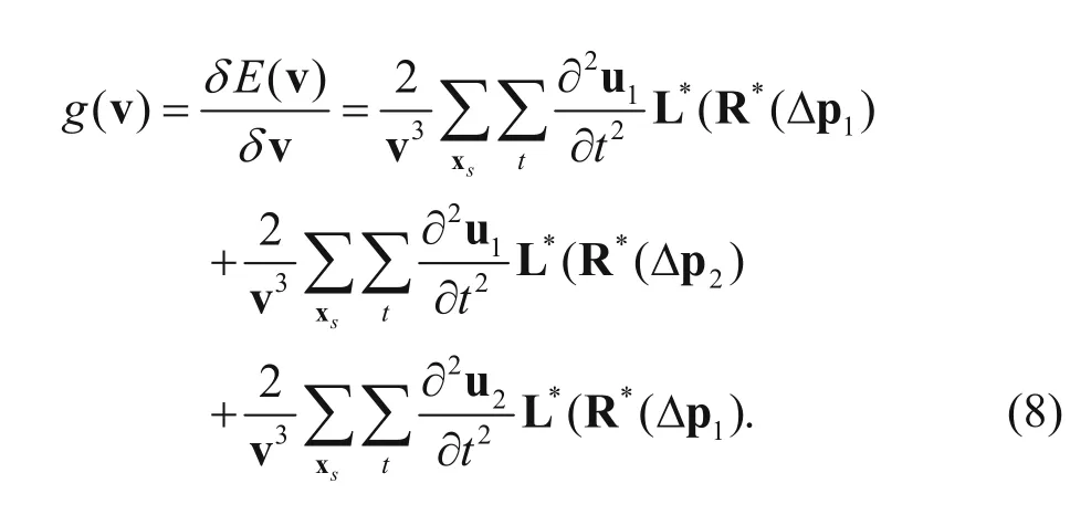
From equation (8) we can find that the first term is the gradient of the reflection wave, and then the latter two terms are the gradient of the second order prismatic wave, where the second term denotes the inner-product of the prismatic back-propagated wavefield and the second order derivative of the reflective forwardpropagated wavefield, and third term denotes the innerproduct of the reflective back-propagated wavefield and the second order derivative of the prismatic forwardpropagated wavefield. We use g(v)reflect, g(v)prismland g(v)prism2to express the gradient of the reflection wave as prism1 and prism2, respectively, and then
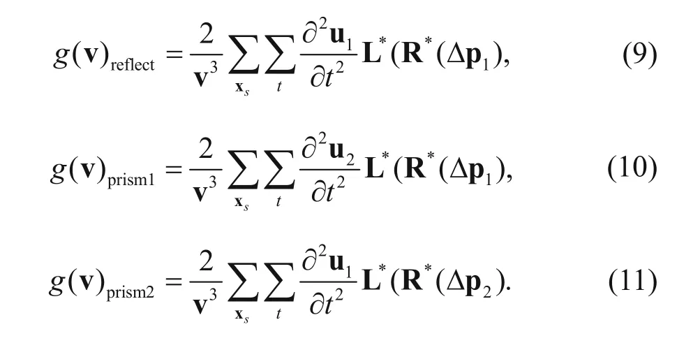
Thus, the gradient of the prismatic waveform inversion (PWI) is
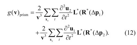
The input data to the PWI are the full wavefield data rather than the prismatic wavefield data. In the inversion, we use equation (12) to separate the prismatic waves. The steps for calculating the gradient direction of the prismatic waveform inversion method are the following.
(1) Obtain imaging results using the traditional RTM.

where

(2) Use the RTM imaging results as the reflection model and the Born approximation to the forward modeling and backward propagation, which is expressed by B and B*, respectively. The propagation path of prism1 is that seismic waves reach the depositional interfaces first and then the salt dome flanks, so the second order prism1 wavefield can be realized by Born approximation. The propagation path of prism2 is that seismic waves reach the salt dome flanks first and then the depositional interfaces, so the second order prism2wavefield can be realized by back-propagated Born approximation (Dai, 2012).
(3) Calculate the gradient direction of PWI. The gradient direction of PWI comprises prism1 and prism2, as shown by the following equations

where

It should be noted that the residual is that of the synthetic and the observed records.
(4) Add the two parts to obtain the gradient direction of PWI as follows:
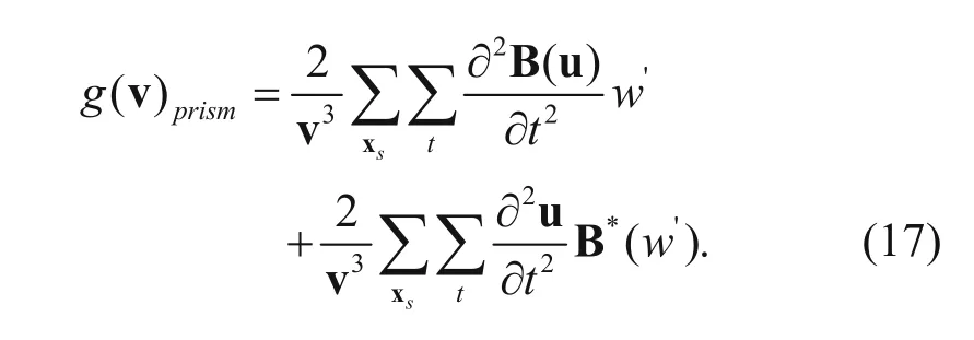
The updated equation of PWI for velocity is

where αkis the step that can be calculated by minimizing the objective function E

We use the linear search method (Mora, 1987) or the parabolic interpolation method (Vigh and Starr, 2008) to calculate the step αk.
The advantages of PWI are the following. The method is 1) weakly dependent on the information of the initial model for high and steep structures and (2) makes full use of the second-order prismatic waves, which carry the information, to improve the inversion precision and resolution. However, PWI has several obvious disadvantages. (1) The efficiency of PWI is twice as that of FWI for every iteration. (2) The PWI does not make full use of the full wavefield. Thus, in this study, we combine the FWI and PWI to form a prismatic and full waveform joint inversion method. In the proposed method, the FWI and PWI are used separately to update the velocity model. In the process of calculating the gradient, the sediments are regarded as secondary sources. Thus, the dependence on the initial model is very low and when the information regarding the high and steep structure in the initial velocity model is little or missing, the proposed joint inversion obtains the steep structure accurately.
Numerical examples
Sag model
First, we use a simple sag model to test the proposed prismatic and full waveform joint inversion method and show its advantages over traditional FWI. The sag model (Figure 1a) consists of three horizontal layers in a vertical sag structure. The size of the model is 1600 m × 1600 m with grid spacing of 5 m. The parameters for the forward modeling are 50 sources evenly distributed in the horizontal direction with frequency of 25 Hz. The first source is located at x = 0 at 5 m depth and the shot interval is 32 m. For a fixed observation system, all receivers are located at the surface at 5 m intervals in the horizontal direction. The time interval is 0.5 ms and the total recording time is 1s. We use the prismatic waves,and the traditional FWI and the proposed full waveform joint inversion to update the velocity. Figure 1b shows the initial velocity. When using the joint inversion method, the PWI and FWI are used alternately to update the velocity for the previous 20 iterations, whereas after the 20th iteration only FWI is used to update the velocity. Figure 1c shows the inverted velocity for the 65th iteration using traditional FWI, whereas Figure 1d shows the same but for the prismatic and full waveform joint inversion. By comparing Figures 1c and 1d, we find that the inversion results are more accurate when using the joint inversion method. To better compare the inversion results of the two methods, we amplify the vertical reflection layer shown by the red dotted boxto obtain the local view, as shown in Figure 2. From Figures 2c and 2d, we infer that the inverted vertical layers obtained with the prismatic and full waveform joint inversion method better match the real model. The convergence speed is faster and the inverted location is more accurate, as well as the velocity. To compare the convergence between the proposed prismatic and full waveform joint inversion and traditional FWI, we show the relative errors in Figure 3, where the convergence curve of FWI is initially faster than our method because the calculation time of every iteration for PWI is twice that of FWI. With increasing number of iterations, the convergence speed of the proposed method is much faster than the traditional FWI method, and the final relative error is significant less. The errors suggest that the proposed prismatic and full waveform joint inversion method is faster and more accurate when dealing with steep structures.

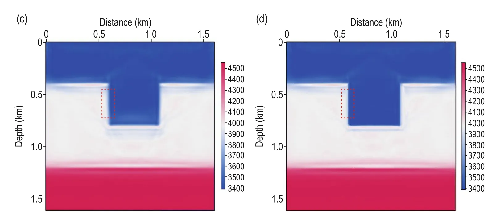
Fig.1 Sag model: (a) real velocity; (b) initial velocity; (c) inverted velocity for the 65th iteration using the traditional FWI; (d) inverted velocity for the 65th iteration using the proposed prismatic and full waveform joint inversion.
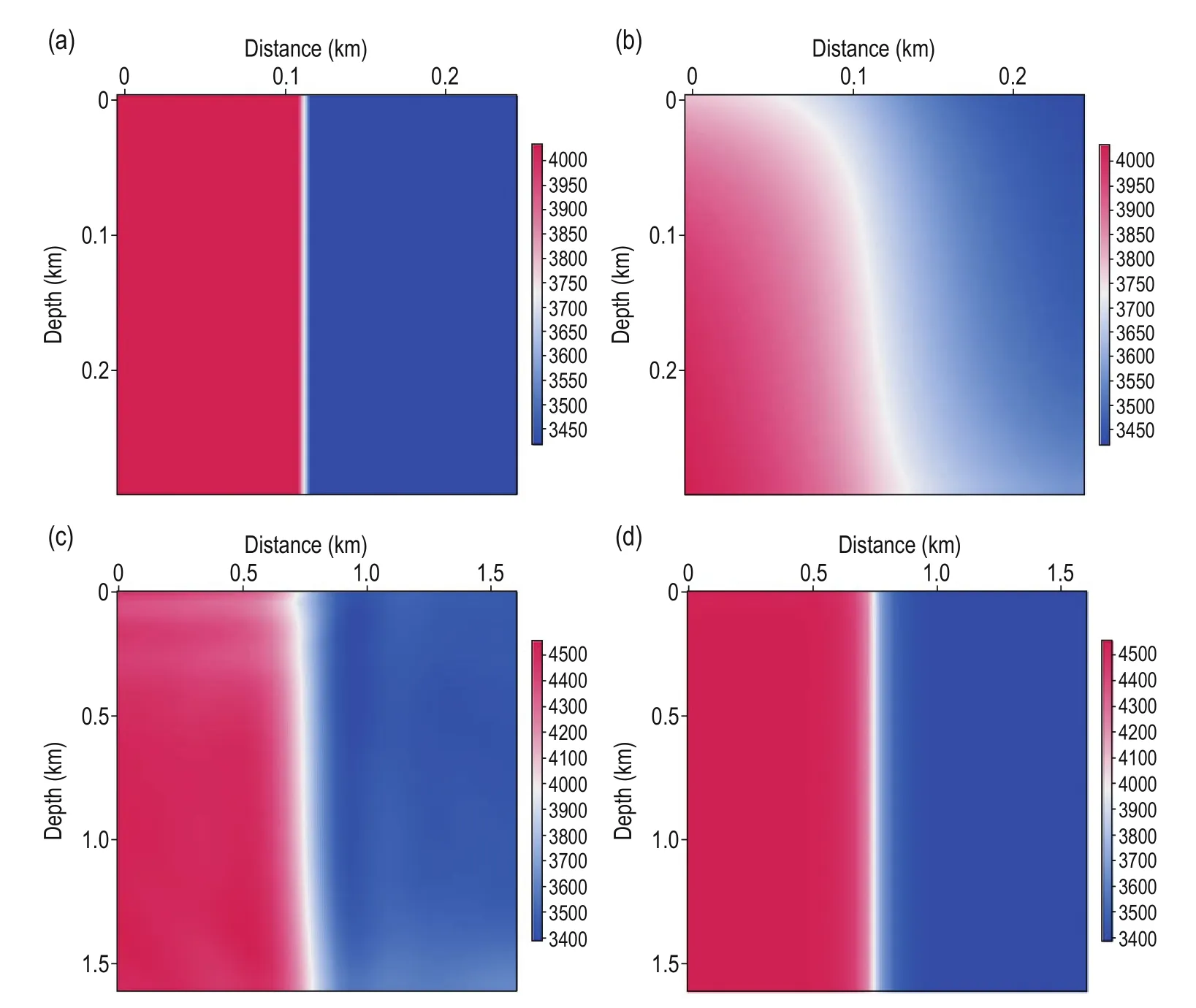
Fig.2 Enlarged view of Fig. 1: (a) real velocity; (b) initial velocity; (c) inverted velocity for the 65th iteration using the traditional FWI; (d) inverted velocity for the 65th iteration using the prismatic and full waveform joint inversion.
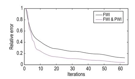
Fig.3 Relative errors.
Marmousi2 model
Next, we use the international standard Marmousi2 model (Figure 4a) to test the applicability of the proposed method. The Marmousi2 model has a salt body in the middle, three big shallow faults, and several highvelocity bodies in the edges. The size of the model is 5520 m × 3312 m and the horizontal and vertical grid spacing is 15m and 8m, respectively. The sampling time is 0.5 ms. The recording time is 3.5 s and the totalnumber of shots are 123. The 25 Hz Ricker wave sources are evenly distributed in the horizontal direction. The first source is at 30m in horizontal direction. In a fixed observation system, each receiver has 369 channels. Figure 4b shows the initial model. We use traditional FWI and the proposed prismatic and full waveform joint inversion method to update the velocity. In the proposed method, the PWI and FWI are used alternately to update the velocity for 20 iterations, and only FWI is used afterward. Figures 5a and 5b show the inversion results for the 10th iteration obtained with the proposed method and traditional FWI method. From the comparison, we find that on the layers, the two algorithms have almost the same inversion speed. However, on the high and steep structures, such as the faults, the inversion speed of the proposed method is much faster than the traditional FWI method. Figure 5c shows the inversion results for the 100th iteration obtained with the proposed method. In this figure, the velocity information for the high and steep structures is well recovered, which suggests that the inversion speed and accuracy of the proposed method for high and steep structures have improved even for inaccurate initial model. Moreover, the overall inversion results of the proposed method are better because the high and steep structures are recovered accurately and with more high-frequency details. Figure 5d shows the inversion result for the 100th iteration with the traditional FWI method. The inversion results for the sediments are satisfactory but the faults and break points in the middle and deep regions are vague as well as the anticline in the deep regions. Figure 6 shows the velocity at 2200 m away from the source, where there are steep faults and an anticline. Clearly, the inversion results with the proposed method better match the real velocity than the traditional FWI method. From the numerical examples for the Marmousi2 model, we infer that the proposed prismatic and full waveform joint inversion method can be adapted to complex models.

Fig.4 Marmousi2 model: (a) real velocity and (b) initial velocity.

Fig.5 Velocity inversion for the Marmousi2 model: (a) after ten iterations using the proposed joint method; (b) after ten iterations using the traditional FWI method; (c) after 100 iterations using the proposed joint method; and (d) after 100 iterations using the traditional FWI method.

Fig.6 Velocity vs depth.
Conclusions
To improve the efficiency and accuracy of the inversion for high and steep structures, we propose the prismatic waveform inversion (PWI) method. The method makes full use of the prismatic wave information to accurately update the velocity at the flanks of salt bodies. The PWI does not depend on the initial model as strongly as the traditional FWI, and can accurately invert the velocity for high and steep structures even if the initial information is poor or missing. However, the calculation time of PWI is twice that of the traditional FWI and it does not utilize the full wavefield.
To increase the advantages of the PWI and overcome its disadvantages, we combine the PWI and FWI to construct the full waveform joint inversion method. In this method, the PWI is used because of its high inversion speed, and PWI and FWI are alternately used to update the velocity. Numerical examples using a sag model and the Marmousi2 model verify the accuracy and effectiveness of the prismatic and full waveform joint inversion.
However what should be noted is that: (1) when the difference between the initial model and the real model is large, the inverted high and steep structures will has some errors, which will affect the accuracy of the following FWI. But with the increase of the iterations, the model will be close to the real model, and steep dip structure and sedimentary can be well restored; (2) The PWI method proposed in this paper has different sampling for different regions, because the propagation paths and area covered are both different between prismatic wave and reflected wave, so PWI and FWI are combined to improve the precision on inverting high and steep structure, and can expand the coverage of inversion for high and steep structure; (3) A lot of full waveform inversion methods such as the envelope inversion, the multi-scale inversion and the full waveform inversion with prior information can obtain good inversion results.The proposed method can be easily applied to these inversion methods to obtain better results.
Acknowledgements
The authors wish to thank Professor Dong Liangguo for his critical and constructive comments and suggestions.
Ao, R. D, Dong, L. G., and Chi, M. X., 2015, Sourceindependent envelope-based FWI to build an initial model: Chinese J. Geophys. (in Chinese), 58(6), 1998–2010.
Asnaashari, A., Brossier, R., Garambois, S., Audebert, F., and Virieux J., 2013, Regularized seismic full waveform inversion with prior model information: Geophysics, 78(2), R25–R36.
Broto, K., and Lailly, P., 2001, Towards the tomogtaphic inversion of prismatic reflections: KIM 2001 Annual Report.
Cavalca, M., and Lailly, P., 2001, Towards the tomographic inversion of prismatic reflections: 71st Annual International Meeting, SEG, Expanded Abstracts, 726–729.
Cavalca, M., and Lailly, P., 2005, Prismatic reflections for the delineation of salt bodies: 75th Annual International Meeting, SEG, Expanded Abstracts, 2350–2354.
Dai, W., 2012, Multisource least-squares migration and prism wave reverse time migration: PhD Thesis, The University of Utah, America.
Dong, L. G., Chi, B. X., Tao, J. X., and Liu, Y. Z., 2013, Objective function behavior in acoustic full-waveform inversion: Chinese J. Geophys. (in Chinese), 56(10), 3445–3460.
Guitton, A., 2010, A preconditioning scheme for full waveform inversion. 80st Annual International Meeting, SEG Expanded Abstracts, 1008–1012.
Hale, D., Hill, N. R., and Stefani, J., 1992, Imaging salt with turning seismic waves: Geophysics, 57(11), 1453–1462.
Hawkins, K., 1994, The challenge presented by North Sea Central Graden salt domes to all DMO algorithms: First Break, 12(6), 327–343.
Krebs, J. R., Anderson, J. E., and Hinkley, D., 2009, Fast full-wavefield seismic inversion using encoded sources: Geophysics, 74(6), WCC177–WCC188.
Li, Y. F., Agnihotri, Y., and Ty, T., 2011, Prismatic wave imaging with dual flood RTM: 81th Ann. Internat. Mtg., Soc. Expl. Geophys., Expanded Abstracts, 3290–3294.
Liu, Y. Z., Yang, J. Z., Chi, B. X., and Dong, L. G., 2015, An improved scattering-integral approach for frequencydomain full waveform inversion: Geophysical Journal International, 202(3), 1827–1842.
Luo, Y., and Schuster, G. T., 1990, Wave-equation traveltime + waveform inversion: 60st Annual International Meeting, SEG, Expanded Abstract, 1223–1225.
Malcolm, A. E., Ursin, B., and Maarten, V., 2009, Seismic imaging and illumination with internal multiples: Geophysical Journal International, 176(3), 847–864.
Marmalyevskyy, N., Roganov, Y., Gornyak, Z., Kostyukevych, A., and Mershchiy, V., 2005, Migration of duplex waves: 75th Ann. Internat. Mtg, Soc. Expl. Geophys., Expanded Abstracts, 2025–2029.
Mora, P., 1987, Nonlinear two-dimensional elastic inversion of multioffset seismic data: Geophysics, 52(9), 1211–1228.
Ren, H. R., 2011, A study of the seismic wave inversion method for imaging in the acoustic media: PhD Thesis, Tongji University, Shanghai.
Vigh, D., and Starr, E. W., 2008, 3D prestack plane-wave, full-waveform inversion: Geophysics, 73(5), 135–144.
Weibull, W., Arntsen, B., and Nilsen, E., 2012, Initial velocity models for full waveform inversion: 82th Ann. Internat. Mtg., Soc. Expl. Geophys., Expanded Abstract, 1–4.

Qu Ying-Ming, China university of petroleum (Huadong), Ph.D candidate. Student at the Department of Geophysics, China University of Petroleum (Huadong) from year 2008. His research interests are forward modeling, migration, full waveform inversion method.
Manuscript received by the Editor November 5, 2015; revised manuscript received August 17, 2016.
*This study work wad financially supported by the National 973 Project (No. 2014CB239006 and 2011CB202402), the Natural Science Foundation of China (No.41104069 and 41274124), and the Graduate Student Innovation Project Funding of China University of Petroleum (No. YCXJ2016001).
1. Department of Geophysics, School of Geosciences, China University of Petroleum, Qingdao 266580, China.
2. Chinese Academy of Geological Sciences Institute of Geophysical and Geochemical Exploration, Langfang 065000, China.
♦Corresponding author: Huang Jian-Ping (Email: jphuang@mail.ustc.edu.cn)
© 2016 The Editorial Department of APPLIED GEOPHYSICS. All rights reserved.
杂志排行
Applied Geophysics的其它文章
- Spherical cap harmonic analysis of regional magnetic anomalies based on CHAMP satellite data*
- Coherence estimation algorithm using Kendall’s concordance measurement on seismic data*
- Three-dimensional numerical modeling of fullspace transient electromagnetic responses of water in goaf*
- 3D finite-difference modeling algorithm and anomaly features of ZTEM*
- 3D modeling of geological anomalies based on segmentation of multiattribute fusion*
- Anomalous astronomical time-latitude residuals: a potential earthquake precursor*
