Principle and Experimental Verification of Flexible Caudal Fin Based on Active Torsion Propulsion Mode
2016-12-01GuanYuanlinLiHuafengYangXixinDiSisi
Guan Yuanlin,Li Huafeng,Yang Xixin,Di Sisi
1.School of Mechanical Engineering,Qingdao University of Technology,Qingdao 266100,P.R.China;
2.State Key Laboratory of Mechanics and Control of Mechanical Structures,Nanjing University of Aeronautics and Astronautics,Nanjing 210016,P.R.China;
3.School of Data Science and Software Engineering,Qingdao University,Qingdao 266100,P.R.China
Principle and Experimental Verification of Flexible Caudal Fin Based on Active Torsion Propulsion Mode
Guan Yuanlin1,2,Li Huafeng2*,Yang Xixin3,Di Sisi2
1.School of Mechanical Engineering,Qingdao University of Technology,Qingdao 266100,P.R.China;
2.State Key Laboratory of Mechanics and Control of Mechanical Structures,Nanjing University of Aeronautics and Astronautics,Nanjing 210016,P.R.China;
3.School of Data Science and Software Engineering,Qingdao University,Qingdao 266100,P.R.China
The active torsion propulsion mode of a caudal fin,composed of macro fiber composites(MEC)and carbon fiber orthotropic composite material is proposed.The caudal fin is excited by the piezoelectric structure to vibrate flexibly.The work principle is firstly analyzed by finite element method(EEM)and experiments.Then the caudal fin is optimized to increase the torque and improve the streamline,and the added mass effect from the water is discussed in terms of the frequency of the structure.The torsion resonance frequency is around 103 Hz in the air and decreased by 75%to 25 Hz in the water.Einally,the mean thrust is discussed and measured to be 11 m N at 900 V(Peak to peak)driving voltage.A flexible micro robot is developed and tested.The locomotion velocity and flow velocity is 320 mm/s and 268 mm/s,respectively.The results of the simulation and experiments indicate that the locomotion of the biomimetic aquatic robot has fast movement characteristics.
macro fiber composite;torsion vibration mode;local travelling wave;micro robot
0 Introduction
Lindsey and Webb proposed two classifications based on the locomotion of the fish:Body and/or caudal fin(BCE)and median and/or paired fin(MPE)[1,2].The speed of the fish in the BCE mode is faster than that of the MPE mode.Therefore,most fish move in the BCE mode,e.g.the golden fish shown in Fig.1.The caudal fin includes the active caudal fin and the passive fin.The active bending deformation of the active caudal fin is produced by the muscles, while the passive torsion deformation of the passive caudal fin is implemented by the interaction between the water and active caudal fin,which also propel the fish.
In the past few years,the researchers have mainly investigated the bending deformation of the active caudal fin,such as the large robotsusing the motors and link mechanism[3,4]and the fish-like robots[5]based on the shape memory alloys(SMAs)[6,7],ionic polymer-mental composites(IPMCs)[8,9],and magnetostrictive thin films[10,11].However,the active torsion deformation of the passive caudal fin has rarely been researched.
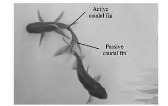
Fig.1 Locomotion of golden fish
*Corresponding author,E-mail address:lihuaf@nuaa.edu.cn.
How to cite this article:Guan Yuanlin,Li Huafeng,Yang Xixin,et al.Principle and experimental verification of a flexible caudal fin based on active torsion propulsion mode[J].Trans.Nanjing Univ.Aero.Astro.,2016,33(5):595-601.
http://dx.doi.org/10.16356/j.1005-1120.2016.05.595
In this paper,the active torsion propulsion of a flexible caudal fin composed of MECs is investigated,based on the transverse shear deformation of the composite plate.The caudal fin is optimized to increase the torque.The structure-fluid model and experiments are built to discuss the added mass effect from the water on the frequency of the caudal fin.The caudal fin and its application are studied.
1 Structure and Materials
The novel piezoelectric material(MEC),developed by NASA[12],yields a better flexibility, and a higher level of strain than the conventional piezoelectric actuators because of its unique structure features.On the other hand,it expands or contracts in the direction of the fiber when an AC voltage(-500—+1 500 V)is applied.The displacement and driving force produced by MEC aloneis too small to drive an object,e.g.the biomimetic fish.Therefore,it is essential to unite MEC with other structures to obtain a large deformation.The carbon fiber composite is utilized as the substrate.Two pieces of MEC are pasted on both sides of the carbon fiber orthogonal composite whose direction is the same as the fiber in MEC by the high shear epoxy adhesion.Table 1 lists the material parameters.The carbon fiber composite is chosen as the substrate.E1and E2represent the elasticity modulus of Directions 1 and 2,respectively,ν12andν21the poission ratios of Directions 12 and 21,respectively.G12is the shear modulus of Direction 12.
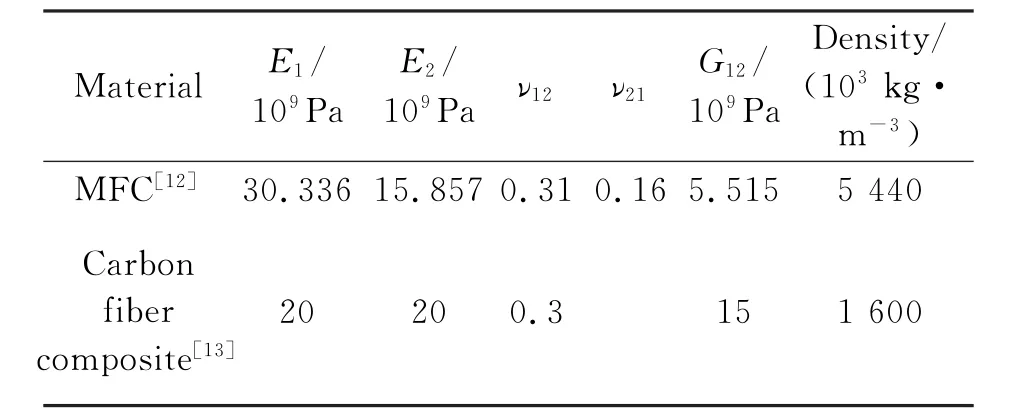
Table 1 Material properties
2 Working Principle and Vibration Analyses
E1,E2and G12are the same for isotropic materials.However,they are different for the anisotropic materials.Specially,G12is smaller than E1and E2.Therefore,the transverse shear deformation of the anisotropic plate is larger than that of the isotropic plate.The torsion vibration mode is excited by the transverse shear deformation of the structure.Thus,the caudal fin employs the torsion vibration mode to mimic the torsion propulsion mode of the passive fin.
The EEM model of the caudal fin is built to analysize the torsion vibration characteristics. The deformation of the body is extremely small based on the big stiffness of the golden fish body in Fig.1.Therefore,the deformation can be ignored.But the deformation of the caudal fin is very large.Hence,the boundary condition of the model is similar to that of the cantilever beam,as shown in Fig.2.The two pieces of MEC are driven by two alternating current(AC)driving voltage of 180°phase differences.In addition,the nonlinear of the geometric is taken into account due to the big deformation.Fig.3(a)shows that the calculated first-order torsion resonance frequency in the air is around 159.48 Hz at 900 V (Peak to peak),when the caudal fin is symmetrically excited.
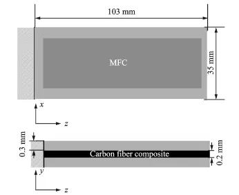
Fig.2 Structure diagram of caudal fin
In order to obtain the torsion resonance frequency,the caudal fin is fabricated and the vibration velocity is measured by laser Doppler vibrometer system(PSV-300E-B),within a frequency band from 0 to 300 Hz and a voltage 100 Vp.Theresults are shown in Fig.3(b).The larger vibration velocity is at the resonance frequency.Thus, the frequencies at the peaks correspond to the resonance frequencies.Therefore,there exist three resonance frequencies in Fig.3(b).The measured torsion resonance frequency is 153.5 Hz and the vibration pattern is represented by the colorful chart in Fig.3(b).The EEM result is confirmed. In addition,different colors represent the distribution of structure deformation:″red″is upward,″green″is downward and″black″is middle.To analysize the torsion vibration pattern of the caudal fin,the working area surface is measured when the operating frequency is 153.5 Hz and the driving voltage is 100 Vp.Fig.3(c)shows that there exists a nodal point and there are two outof-phase deformations at the two sides of the nodal point.Therefore,there exist the local travelling waves in the plate which are the sinusoidal waves with peaks and valleys moving along the concentric circles.Thus,the torsion process is implemented.
In order to increase the torque and improve the streamline of the caudal fin,an added trapezoid structure is optimal based on the deformation analysis of the triangle structure,the trapezoid one and rectangular one by EEM.The new optimized structure is shown in Fig.4(a)and is analyzed.Figs.4(b,c)show the vibration parameters of the new caudal fin under EEM and experiments under the same condition as that in Fig.3. There also exist three resonance frequencies.The torsion resonance frequencies are 103.69 Hz under EEM and 103 Hz in the test,respectively, and the calculated displacement is 1.514 7 mm. The frequency is 50 Hz lower compared with that in Fig.3 due to the added mass effect.In addition,the torsion pattern is asymmetrically excited.The deformation of the trapezoid is larger than that of the rectangular.
Sader and his co-workers accounted for the hydrodynamic effects on atomic force microscopy cantilevers[14-17].The resonance frequencies of cantilever beams can depend strongly on the fluid in which they are immersed.The fluid has a sig-nificant impact on the frequencies and displacement.A series of EEM calculation and the vibration velocity measured in the water are executed for the caudal fin.The density of the water is 1 000 kg/m3and the acoustic velocity is 1 480 m/ s.The results are shown in Fig.5.The calculated torsion frequency is about 25.1 Hz,the displacement is 0.688 5 mm,and the black edge represents the edge of the water tank.It is found that the frequency and displacement separately decline by 75%and 0.8 mm compared with that in the air due to the added mass effect of the water,and the zero position also moves down.In addition, the measured torsion resonance frequency is around 25 Hz in the water.The impact of the wa-ter on the frequency and the EEM result are confirmed.
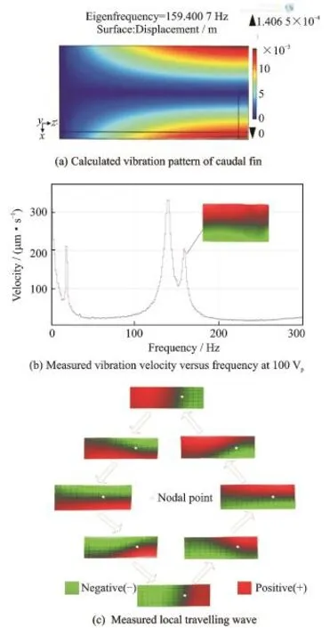
Fig.3 Vibration analysis of caudal fin

Fig.4 Vibration analysis of optimized caudal fin
3 Results and Discussions
3.1 Thrust
It is found that the two-dimension pattern is similar to the bending deformation in the water in Fig.5(b).Thus,the thrust is analyzed under the bending deformation of the caudal fin in order to analysize the interaction between the caudal fin and the water.
Fig.6(a)shows the diagram of the vortex during a period of the caudal fin.The pressure direction changes twice just as the vertical speed di-rection of the caudal fin changed twice.It can be seen that the vortex shed when t=T/4 and t= 3T/4.After that,a new vortex is produced.It is found that the vortex changes a pulsation in every half period.Therefore,the thrust corresponding to the vortex changes two pulses in a period. Fig.6(b)shows the curve of the calculated thrust coefficient during a period.It is seen that the positive range of the thrust is close to the negative one because the fin swings with the same angle apart from the axis z at t=T.Therefore, the average thrust coefficient is small,and the positive value is larger than the negative one. Thus,the direction of the average thrust is to -z.
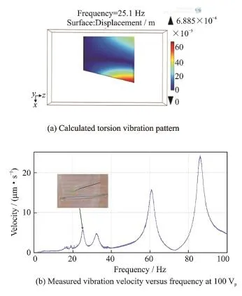
Fig.5 Vibration analysis of new caudal fin in the water
According to the above calculation,the torsion frequency of the caudal fin is around 25 Hz. Therefore,the frequency band is between 22 Hz and 30 Hz with a fine increment of 0.5 Hz.The driving voltages are 700 V and 800 V separately without DC offset and 900 V(Peak to peak)with DC offset.
A measurement system for the thrust is built,and the lever principle is adopted.The side of the aluminum bar fixed with the caudal fin wasimmersed in the water and the other side was connected to the force sensor above the water.The proportion of the amplification is 1∶20.Fig.7 shows the curves of mean thrust frequency response.As the frequency increases,the thrust increases first and then decreases.When the driving voltage increases,the mean thrust keeps unchanged at the same driving frequency.It indicates that the driving voltage does not affect the mean thrust when the driving voltage exceeds 700 V.The frequency mainly affects the thrust. The maximum mean thrust is 11 m N at 28.5 Hz. The deviation of the resonance frequency may be caused by the vibration of the bar.
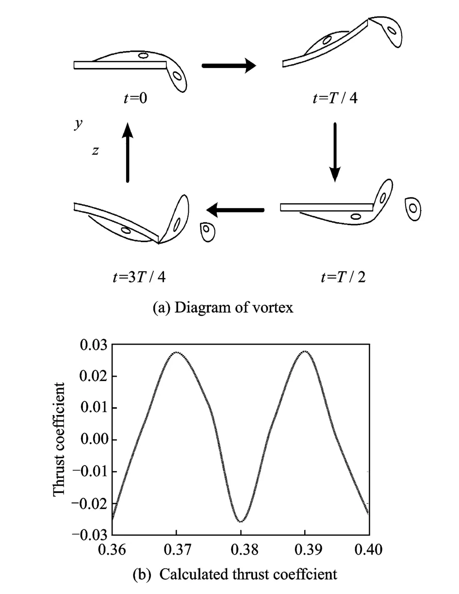
Fig.6 Diagram of vortex and calculated thrust coefficient
3.2 Locomotion velocity and flow velocity
An aquatic robot is designed under the low density float and a mass is used to constrain the amplitude of the head.In addition,it is necessary to balance the gravity and the buoyancy of the float so as to keep the body in water vertical.The movement process of the aquatic robot is recorded by the camera to research the locomotion of theaquatic robot.The Unidata STARELOW 6526 ultrasonic Doppler is adopted to measure the mean flow velocity for the analysis of the hydrodynamic performance in Fig.8.
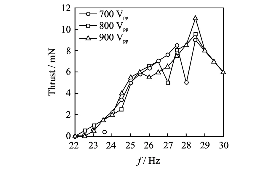
Fig.7 Experimental mean thrust curves at 700,800 and 900 V driving voltage
The results of the locomotion velocity and the flow velocity are shown in Fig.9.As the frequency increases,the results increase first and then decrease.It can be seen that the resonance frequency of the micro aquatic robot is around 26 Hz.The deviation of the resonance frequency between the micro aquatic robot and the caudal fin may be caused due to the effect of the structure.In addition,the velocity increases when the driving voltage increases.The maximum locomotion velocity and the maximum flow velocity are 322 mm/s and 268 mm/s,respectively.According to the results,the micro aquatic robot moves steadily.
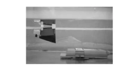
Fig.8 Measurement system of flow velocity
4 Conclusions
A caudal fin using MECs and carbon fiber orthogonal composite is proposed.The active tor-sion is simulated by COMSOL based on the transverse shear of the composite plate.The caudal fin is optimized to increase the torque.The experimental vibration parameters are measured and the EEM results are confirmed.The local travelling wave around the nodal point is produced in the plate and the torsion process is implemented.The structure and structure-fluid vibration model are analyzed by EEM,respectively.The torsion resonance frequency in the air and in the water is calculated to be around 103 Hz and 25.1 Hz.The frequency is decreased by 75%due to the added mass effect from the water.Einally, the micro aquatic robot is developed for the application of the caudal fin.The thrust of the caudal fin is analyzed and measured.The mean thrust level is as high as 11 m N at 28.5 Hz.The locomotion velocity and flow velocity of the micro aquatic robot are 320 mm/s and 268 mm/s at 26 Hz,respectively.The locomotion of the aquatic robot is successfully implemented.
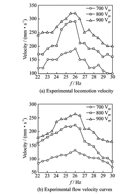
Fig.9 Experimental curves of locomotion velocity and flow velocity
Acknowledgements
This work was supported by the Natural Science Eoundation of China(No.5175250),the Eunding of Jiangsu Innovation Program for Graduate Education and the Eundamental Research Eunds for the Central Universities(No.CXLX12_0144),the Science and Technology Plan Project of Shandong Colleges and Universities (No.J161B06),the Priority Academic Program Development of Jiangsu Higher Education Institutions(PADA).
[1] LINDSEY C C.Eorm function and locomotory habits in fish[M].New York:Academic Press,1978:1-100.
[2] WEBB P W.The biology of fish swimming[M]// Mechanics and physiology of animal swimming. Cambrige:Cambrige University Press,1994:45-62.
[3] LOW H K,WILLY A.Biomimetic motion planning of an undulating robotic fish fin[J].Journal of Vibration and Control,2006,12(12):1337-1359.
[4] NAKASHIMA M,Ono K.Dynamics of two joint dolphin like propulsion mechanism[J].Transactions of the Japan Society of Mechanical Engineers,Series B,1996,62(602):3599-3606.
[5] SEKIGUCHI W,TAKAHASHI N,NODA S,et al. Numerical and experimental study of lure moving in water[J].Transactions of Nanjing University of Aeronautics and Astronautics,2013,30(3):257-259.
[6] SHINJO N,SWAIN G W.Use of a shape memory alloy for the design of an oscillatory propulsion system[J].IEEE Journal of Oceanic Engineering, 2004,29(3):750-755.
[7] ROSSI C,COLORADO J,CORAL W,et al.Bending continuous structures with SMAs:A novel robotic fish design[J].Bioinspiration&Biomimetics, 2011,6(4):045005.
[8] AURELI M,KOPMAN V,POREIRI M.Eree-locomotion of underwater vehicles actuated by ionic polymer metal composites[J].IEEE/ASME Transactions on Mechatronics,2010,15(4):603-614.
[9] ZHENG C,SHATARA S,TAN X B.Modeling of biomimetic robotic fish propelled by an ionic polymer metal composite caudal fin[J].IEEE/ASME Transactions on Mechatronics,2010,15(3):448-459.
[10]ZHANG Y S,LIU G J.Design,analysis and experiments of a wireless swimming micro robot[C]//2005 IEEE International Conference in Mechatronics and Automation.[S.l.]:IEEE,2005:946-951.
[11]ZHANG Y S,LIU G J.Wireless swimming micro robot:Design,analysis and experiments[J].The ASME Journal of Dynamic Systems,Measurement, and Control,2009,131(1):011004.
[12]Smart Material Corp.MEC supplier with the NASA standard[EB/OL].[2014-05-03].http://www. smart-material.com.
[13]SHINTAKE J,MING A,SHIMOJO M.Development of flexible underwater robots with caudal fin propulsion[C]//Proceedigs of the IEEE/RSJ International Conference on Intelligent Robots and Systems.Taipei,China:IEEE,2010:940-945.
[14]SADER J E.Erequency response of cantilever beams immersed in viscous fluids with applications to the atomic force microscope[J].Journal of Applied Physics,1998,84(1):64-76.
[15]VAN EYSDEN C A,SADER J E.Erequency response of cantilever beams immersed in viscous fluids with applications to the atomic force microscope:Arbitrary mode order[J].Journal of Applied Physics, 2007,101(4):044908.
[16]CHON J W M,MULVANEY P,SADER J E.Experimental validation of theoretical models for the frequency response of atomic force microscope cantilever beams immersed in fluids[J].Journal of Applied Physics,2000,87(8):3978-3988.
[17]VAN EYSDEN C A,SADER J E.Resonant frequencies of a rectangular cantilever beam immersed in a fluid[J].Journal of Applied Physics,2007,100 (11):114916.
Dr.Guan Yuanlin received Ph.D.degree in measurement technology and instrumentation from Nanjing University of Aeronautics and Astronautics in 2015.In 2015,he joined in School of Mechanical Engineering,Qingdao University of Technology.His research is focused on the application of the smart material,the energy harvest,the machinery fault diagnosis and relevant fields.
Prof.Li Huafeng received Ph.D.degree in electronics engineering from Huazhong University of Science and Technology,Wuhan,China,in 2002.In 2003,he joined in the Precision Driving Laboratory,Nanjing University of Aeronautics and Astronautics.His research has focused on the driving control systems of the ultrasonic motor,the artificial muscle and other new types of the actuator.
Dr.Yang Xixin received Ph.D.degree in computer science and technology from Ocean University of China in 2012.In 2012,she joined in School of Data Science and Software Technology,Qingdao University.Her research is focused on the application of the smart material,control of the autonomous underwater vehicle and relevant fields.
Ms.Di Sisi is a Ph.D.candidate in Key Laboratory of Mechanics and Control of Mechanical Structures from Nanjing University of Aeronautics and Astronautics.Her current field of interest is focused on the application of smart material and the driving control system of the ultrasonic motor.
(Executive Editor:Xu Chengting)
TH111;TH14 Document code:A Article ID:1005-1120(2016)05-0595-07
(Received 22 August 2014;revised 16 November 2015;accepted 2 January 2016)
杂志排行

Transactions of Nanjing University of Aeronautics and Astronautics的其它文章
- Mechanism and Process of Sulfate Attack on Roller Compacted Concrete with MgO Expansive Agent
- Mission-Oriented Configuration Model of Aircraft Carrying Spares and Dynamic Optimization Policy
- Numerical Simulation of Warm Forming Behavior of High Strength Aluminum Alloy 7075
- Dissolution Characteristics of New Titanium Alloys in Electrochemical Machining
- Energy-Efficient Process Planning Using Improved Genetic Algorithm
- Model of Autonomous Positioning Through Associating Environment Memory Information