Machining of a film-cooling hole in a single-crystal superalloy by high-speed electrochemical discharge drilling
2016-11-23ZhangYanXuZhengyangZhuYunZhuDi
Zhang Yan,Xu Zhengyang,Zhu Yun,Zhu Di
College of Mechanical and Electrical Engineering,Nanjing University of Aeronautics&Astronautics,Nanjing 210016,China
Machining of a film-cooling hole in a single-crystal superalloy by high-speed electrochemical discharge drilling
Zhang Yan,Xu Zhengyang*,Zhu Yun,Zhu Di
College of Mechanical and Electrical Engineering,Nanjing University of Aeronautics&Astronautics,Nanjing 210016,China
Electrical discharge machining(EDM);Electrochemical machining(ECM);Film-cooling hole;Hybrid technique;Single crystal;Taguchi methods
Single-crystal superalloys are typical advanced materials used for manufacturing aeroengine turbine blades.Their unique characteristics of high hardness and strength make them exceedingly difficult to machine.However,a key structure of a turbine blade,the film-cooling hole,needs to be machined in a single-crystal superalloy;such machining is challenging,especially considering the increasing levels of machining efficiency and quality demanded by the aeroengine industry.Tube electrode high-speed electrochemical discharge drilling(TSECDD),a hybrid technique of high-speed electrical discharge drilling and electrochemical machining,provides high machining efficiency and accuracy,as well as eliminating the recast layer.In this study,TSECDD is used to machine a film-cooling hole in a nickel-based single-crystal superalloy(DD6).The Taguchi methods of experiment are used to optimise the machining parameters.Experimental results show that TSECDD can effectively drill the film-cooling hole;the optimum parameters that give the best performance are as follows:pulse duration:12 μs,pulse interval:30 μs,peak current:6 A,and salt solution conductivity:3 mS/cm.Finally,a hole is machined by TSECDD,and the results are compared with those obtained by electrical discharge machining.TSECDD is found to be promising for improving the surface quality and eliminating the recast layer.
1.Introduction
In the aerospace industry,to enhance the thermal efficiency and power of gas turbines,turbine blades and vanes are usually required to operate at extreme turbine inlet temperatures that are higher than the melting points of metals.1,2Therefore,film-cooling technology is well established and widely used to protect turbine components from overheating.3Film-cooling holes are the most critical structures used in film-cooling technology,and they are extensively used and located all over thesurfaces of blades and vanes.4These holes characteristically have small diameters and exist in large numbers.5Hence,the fabrication of film-cooling holes has always been a critical aspect of aeroengine engineering.
Because of the increasing performance demands for gas turbines that are to be used in extreme applications,difficultto-cut materials with unique metallurgical properties have been developed.6Film-cooling holes are also created in difficult-to-machine materials such as nickel-based superalloys and titanium alloys.7Currently,nickel-based single-crystal superalloys,which are one of the most advanced superalloys,are widely used for the fabrication of critical components in the aeroengine system,such as turbine blades and nozzle guide vanes.8Compared to other superalloys,a nickel-based singlecrystal superalloy has a higher temperature-withstanding capability,which can improve the thermal efficiency of materials.9The superior strength and high-temperature resistance of nickel-based single-crystal superalloys are attributed to the high volume fraction of regularly aligned cubical γ′precipitates coherent with the γ matrix.10Ordered Ni3Al(γ′phase),which occupies up to 70 vol%in this kind of superalloy,offers high strength to the single-crystal superalloy and makes it difficult to cut.11Hence,the fabrication of film-cooling holes is extremely difficult,especially by traditional machining processes.
So far,little attention has been paid to the drilling of a single-crystal superalloy without the formation of a recast layer.Thus,no effective method exists that can be used to create film-cooling holes with high speed and without a recast layer.Laser drilling provides excellent machining efficiency;however,the disadvantage of this process is that a recast layer is formed.12In addition,it is very difficult to protect the nonmachining area,especially the far face of the passage inside a turbine blade,from damage during the fabrication of a filmcooling hole.6,13Although electrolyte jet drilling does not result in the formation of a recast layer,its machining eff iciency is relatively low and the machining accuracy and quality also need to be improved.14,15Electrical discharge machining(EDM)is an extensively accepted technology for the fabrication of film-cooling holes.Its unique feature is that it can use thermal energy to machine electrically conductive parts regardless of the hardness.However,EDM causes a rough surface with a recast layer and a heat-affected zone to be formed beneath the machined surface.16,17Compared to EDM,electrochemical machining(ECM)has the advantages of good surface finish,absence of residual stress,no tool wear,little burr,and little distortion of holes;however,its machining eff iciency is relatively low.18,19Hence,a single process cannot satisfy the rapidly increasing demands for machining efficiency and quality in aeroengine manufacturing.
In view of the above discussion,tube electrode high-speed electrochemical discharge drilling(TSECDD)is proposed.In this process,tube electrode high-speed electrical discharge drilling and ECM are innovatively combined.By using a low-conductivity salt solution,electrochemical dissolution and electrical discharge erosion are made to occur in the same process.In the frontal gap,material removal mainly depends on tube electrode high-speed electrical discharge drilling,which allows a high machining speed to be achieved.In the lateral gap,as the machining process proceeds,a transition occurs from EDM to ECM.When the lateral gap exceeds the critical discharge gap,material removal is purely by ECM,which serves to remove the recast layer formed by EDM.In this way,TSECDD achieves both a high machining speed and good surface finish.20
So far,very few studies have been conducted on the fabrication of film-cooling holes in single-crystal superalloys without the formation of a recast layer and at high machining speeds.For the advancement of aerospace manufacturing,it is essential to develop a machining technology for singlecrystal superalloys that can be used to obtain film-cooling holes at high speeds and without a recast layer.Therefore,attention has been paid to the fabrication of a film-cooling hole in an advanced single-crystal superalloy.In this study,TSECDD is employed.To further improve the machining speed and quality,an experiment is performed to optimise the machining parameters,namely,the pulse duration,pulse interval,peak current,and salt solution conductivity.Finally,film-cooling holes are obtained using the optimum parameters for nickel-based single-crystal superalloys.
2.Principle of TSECDD
TSECDD is a hybrid process that combines tube electrode high-speed electrical discharge drilling and ECM.In the entire process,a tube electrode is employed as the tool cathode,and a salt solution,which acts as the work fluid for EDM and ECM,is continuously provided from the tube electrode at a high speed.Fig.1 illustrates the mechanism of TSECDD.
As shown in Fig.1(a),at the initial stage of machining,the tube electrode moves towards the workpiece.When the electrode–workpiece gap is smaller than the theoretical discharge gap,electrical discharge,as well as electrochemical machining with mass hydroxide precipitates and bubbles,occurs in the inter-electrode gap.At this moment,the workpiece material removal mainly depends on EDM occurring at the frontal end face of the tube electrode,while the effect of an electrochemical reaction based on the ion dissolution is relatively low.Hence,the machining gap rapidly expands in the feed direction,and tube electrode high-speed electrical discharge drilling plays a dominant role at this stage.
In Fig.1(b),it can be seen that as the machining process proceeds,the frontal end face of the tube electrode starts to drill into the workpiece;the frontal gap is smaller than the theoretical discharge gap.At this moment,both electrical discharge and electrochemical dissolution occur in the electrodeworkpiece gap including the frontal gap and the side gap,simultaneously.Thereby,the machining gap rapidly expands in the axial and radial directions of the tube electrode.When the lateral gap distance is larger than the critical distance,EDM gradually stops while the electrochemical dissolution is kept all the time.Therefore,the machining process including EDM and ECM begins to convert to pure ECM in the lateral gap,whereas in the frontal gap,the material removal mainly depends on high-speed electrical discharge drilling.
After the front end face of the tube electrode drills into the workpiece(Fig.1(c)),the side gap rapidly surpasses the critical discharge gap.EDM completely stops,and ECM becomes the dominant process accompanied by mass hydroxide precipitates and bubbles in the lateral gap.The side gap formed after EDM stops is considered as the initial gap for material dissolution;the recast layer and cracks generated by EDM are removed by the electrochemical dissolution at the side gap.
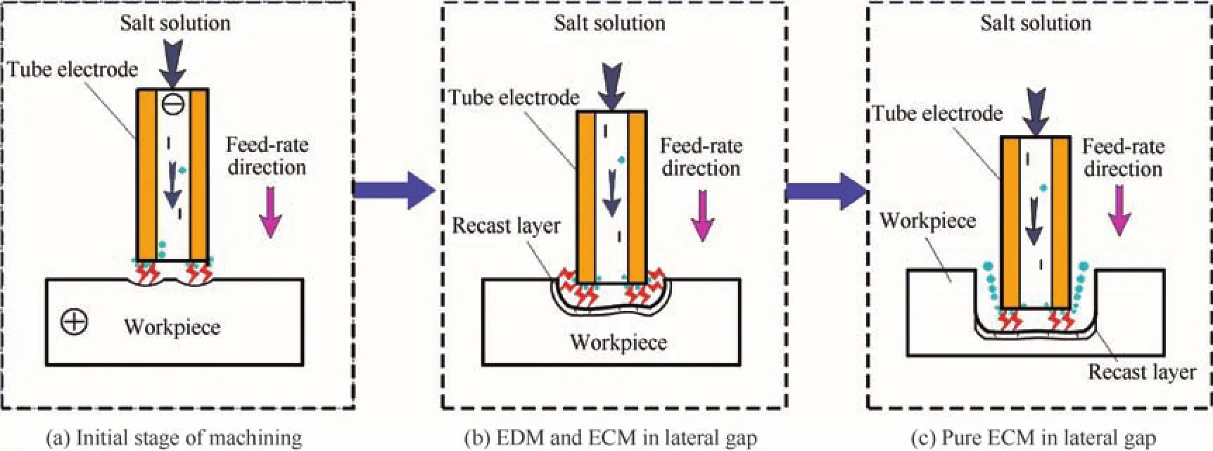
Fig.1 Mechanism of TSECDD.
The most important aspect of TSECDD is that it combines tube electrode high-speed electrical discharge drilling and ECM into a unique process.The tube electrode is used to perform electrical discharge high-speed drilling at the frontal gap,whereby the machining speed is kept at a high level.Furthermore,the use of a low-conductivity salt solution improves the electrochemical dissolution effects at the side gap;thus,the recast layer generated after EDM stops could be removed by ECM at the side wall of the hole.Hence,TSECDD can be employed to drill a film-cooling hole at a high speed and without a recast layer.In this study,to obtain high efficiency and a better surface for a single-crystal superalloy,the machining parameters are optimised by performing an experiment.
3.Experimental details
3.1.Machine tool
Fig.2 shows the photograph of a specially developed machine tool.In this study,parameter optimisation experiments are performed on this tool.This machine tool is designed with six working axes,defined as the linear axesX,Y,Z,andSand the rotary axesBandC.Because of these axes,this machine tool can satisfy the complex processing requirements of film-cooling holes,especially those of various angle holes in a turbine blade or vane.The pulse generator and control system are included in the control cabinet to supply the pulse voltage and control the machining process.In addition,this machine tool includes a rotary spindle for drilling;thus,precise experimental results can be obtained.
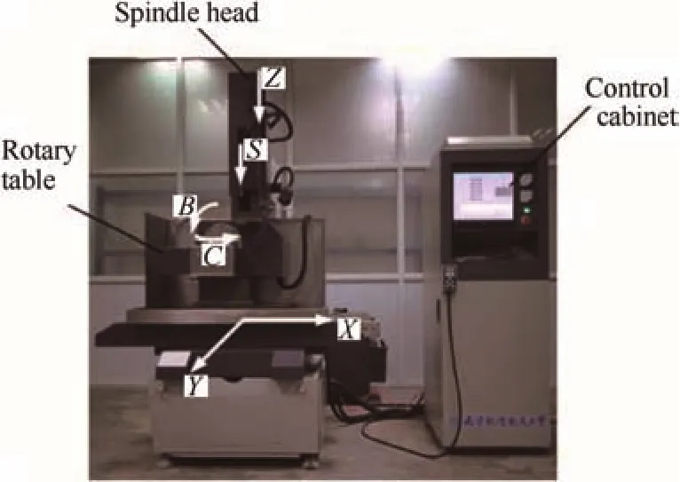
Fig.2 Photograph of the developed six-axis machine tool.
3.2.Materials
DD6 is a nickel-based single-crystal superalloy with good tensile and creep rupture properties.21This superalloy is produced by the screw selection crystal method in a directionally solidified furnace.Because ofitshigh rigidity,good hightemperature corrosion resistance,and good wear resistance,DD6 is well known as an advanced material for manufacturing turbine blades in the aerospace industry.22,23In this study,experiments have been conducted using DD6 as the workpiece with a thickness of 2 mm.The chemical composition of the workpiece is listed in Table 1.In addition,a brass tube is selected as the tool electrode.
3.3.Machining procedures and conditions
In this study,the machining parameters,namely,the pulse duration,pulse interval,peak current,and salt solution conductivity,are optimised by the Taguchi design of experiment method,and the experimental parameters and levels are listed in Table 2.The entire experiment is divided into sixteen parts;each part is repeated five times,and the average value is considered as the final result.This study aims to obtain the optimum combination level of these parameters.In addition,the other parameters that need not to be optimised are kept constant,as listed in Table 3.The machining performance is exam-ined and analysed by considering the material removal rate(MRR),average diameter,taper angle,and the removal of recast layers as optimisation targets.Finally,film-cooling holes are obtained using the optimum parameters for nickel-based single-crystal superalloys.

Table 1 Chemical composition of DD6.
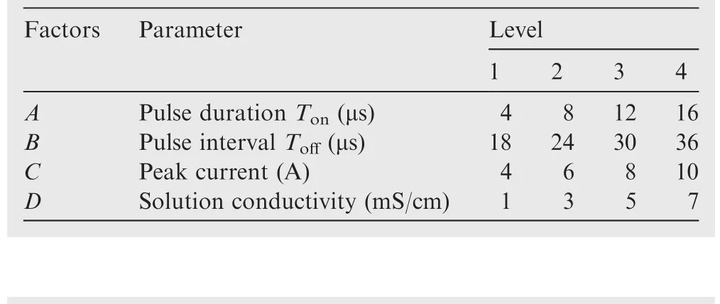
Table 2 Design scheme for experimental parameters and levels.

Table 3 Fixed machining parameters used in optimisation experiments.
4.Experimental results and discussion
The MRR,which is defined as the linear cathode removal rate in the feed direction,is used to evaluate the machining speed.The MRR is calculated by Equation MRR=L/t(whereLis the depth of drilling in μm andtis the machining time in min).The average diameter presents the diameter of the hole machined by TSECDD,while the taper angle shows the difference between the diameters at the entrance and exit of the hole.The average diameter of the hole is given by EquationDaverage=(Dentrance+Dexit)/2,and the taper angle θ of the micro-hole is given by Equation tanθ=(Dentrance-Dexit)/2h(whereDentranceandDexitare the entrance and exit diameters of the hole,respectively,in μm;his the thickness of the workpiece in μm).The entrance and exit diameters of the hole are measured by a three-dimensional profilometer(DVM5000,Leica,Germany).The recast layers are examined by performing a metallography experiment,which includes cutting,polishing,and etching.Then,the recast layers of cross sections are analysed under a metallographic microscope.
4.1.Material removal rate
The experimental results for the MRR under different machining parameters,namely,the pulse duration,pulse interval,peak current,and salt solution conductivity,are listed in Table 4.It can be seen that the solution conductivity and pulse duration are important factors affecting the MRR,whereas the effects of the pulse interval and peak current on the MRR are relatively small.Fig.3 shows the effects of the machining parameters on the MRR in detail.The figure shows that as the pulse duration increases,the MRR increases almost linearly;the MRR decreases with an increase in the peak current up to 8 A and then increases as the peak current increases further.With respect to the solution conductivity and pulse interval,both low and high values are not suitable to obtain a high MRR.The highest MRR is observed for aToffof 30 μs and a solution conductivity of 3 mS/cm respectively.Therefore,both Table 4 and Fig.3 indicate that the optimumparameter combination isA4B3C1D2,namely,a pulse duration of 16 μs,a pulse interval of 30 μs,a peak current of 4 A,and a solution conductivity of 3 mS/cm.
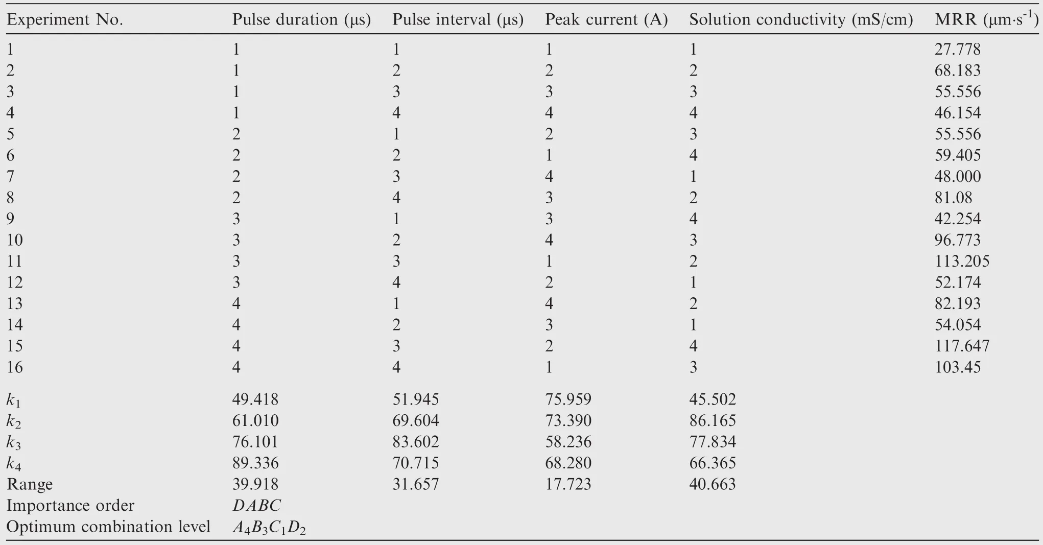
Table 4 Analysis of experimental results in TSECDD for single-crystal superalloy DD6.
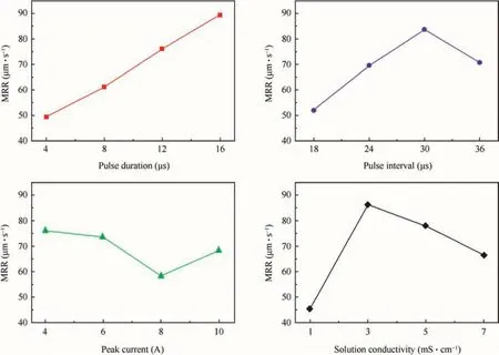
Fig.3 Effects of machining parameters on the MRR.
4.2.Average diameter
Fig.4 shows the effects of the machining parameters,namely,the pulse duration,pulse interval,peak current,and salt solution conductivity,on the average diameter.An upward trend is observed in the average diameter asTonincreases up to 16 μs.This is because a longer pulse duration not only improves material removal in the feed direction but also enlarges the side gap.As for the peak current,its effect on the average diameter is not obvious,as shown in Fig.4(c).In addition,as the salt solution conductivity increases,the average diameter decreases to its minimum value and then increases steadily.The average diameter shows a similar trend as the pulse interval increases.
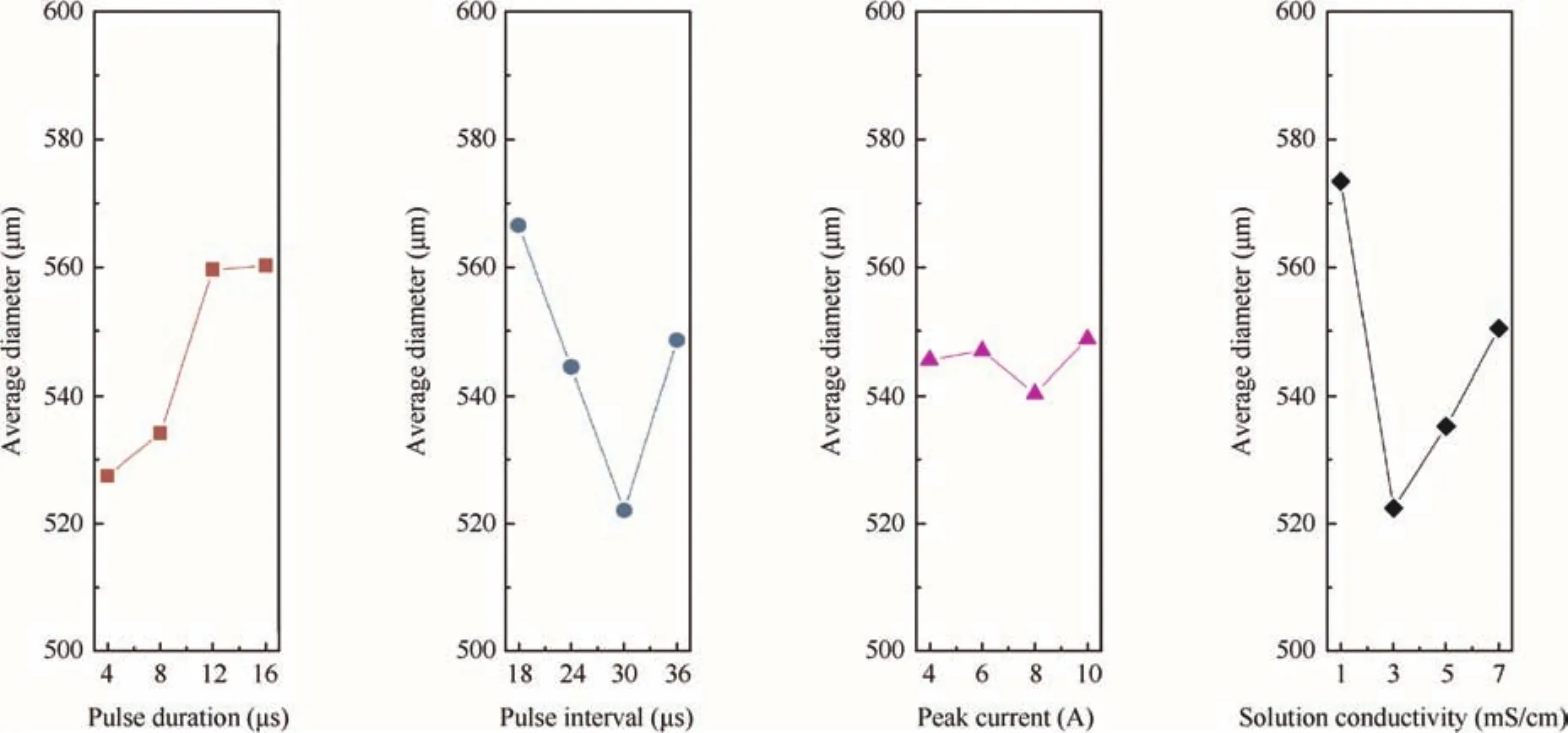
Fig.4 Effects of machining parameters on the average diameter.
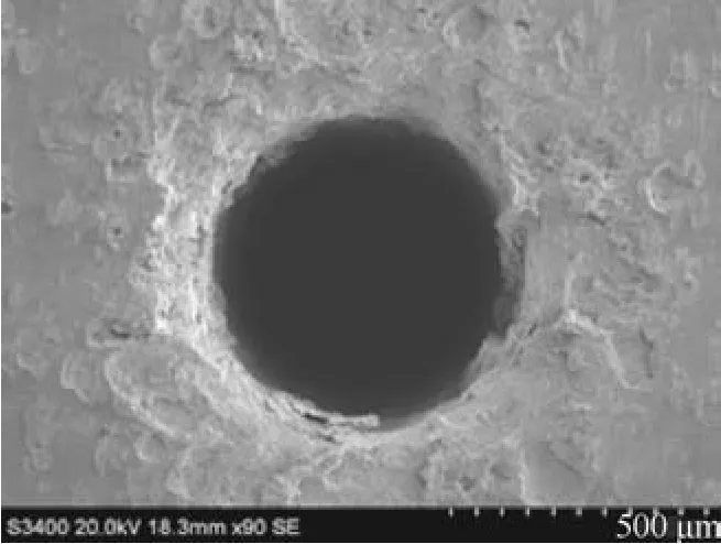
Fig.5 Film-cooling hole fabricated.
To achieve the best performance,the optimum levels of the machining parameters are selected as follows:a pulse duration of 4 μs,a pulse interval of 30 μs,a peak current of 8 A,and a solution conductivity of 3 mS/cm.Fig.5 shows the entrance side image of a micro-hole machined by using this parameter set(pulse duration of 4 μs,pulse interval of 30 μs,peak current of 8 A,and solution conductivity of 3 mS/cm).
4.3.Taper angle
The effects of different machining parameters on the taper angle are shown in Fig.6.It is found that the taper angle increases steadily with the pulse duration.As the pulse duration increases,the lateral gap generated by electrochemical dissolution expands.The expansion is more obvious at the entrance of the hole because of the longer machining period.Thus,a longer pulse duration results in a larger taper angle.Moreover,it can be found that as the pulse interval increases,the taper angle decreases sharply and then increases;the effect of the pulse interval on the taper angle is the same as that of the solution conductivity.In contrast,the taper angle tends to increase to its maximum value and then decrease as the peak current increases.For higher machining efficiency,the taper angle should be set to lower values.Therefore,it can be inferred that to obtain a lower taper angle and better dimensional accuracy,the ideal choice of the machining parameter set is as follows:a pulse duration of 4 μs,a pulse interval of 30 μs,a peak current of 4 A,and a solution conductivity of 3 mS/cm.A hole machined by using this parameter set is shown in Fig.7(pulse duration of 4 μs,pulse interval of 30 μs,peak current of 4 A,and solution conductivity of 3 mS/cm).

Fig.7 Cross-section of a micro-hole machined.
4.4.Recast layer
Here,the removal of the recast layer in TSECDD is analysed by comparison with the corresponding EDM results.The comparison results are shown in Fig.8.As shown in Fig.8(a),the entire surface obtained after EDM is covered by the recast layer,which includes many cracks.As shown in Fig.8(b),after TSECDD,the surface of the hole is mostly devoid of the recast layer;only a few residual recast layers are present at the exit of the hole.It is implied that in TSECDD,electrochemical machining plays an important role in machining the hole wall in the radial direction.Thereby,the recast layer generated by electrical discharge is removed,and the surface becomes smoother.However,the existence of the recast layer to a certain degree at the exit is due to two reasons.Firstly,the region near the exit requires the shortest period to dissolve;therefore,the time available is insufficient to dissolve the recast layer completely.Secondly,while the workpiece is being drilled,the work fluid flows away from the exit;thus,the lack of fluid in the lateral gap causes the collapse of electrochemical dissolution.This study aims to reduce the residual recast layer by performing an optimisation experiment.
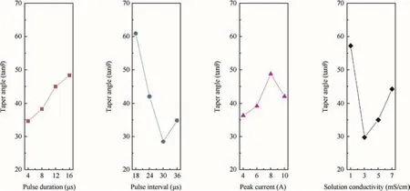
Fig.6 Effects of machining parameters on the taper angle.
The residual recast layers at the exit are sequentially shown in Fig.9 according to the experimental order,which is the same as the order listed in Table 4.The effects of different machining parameters on the recast layer are analysed by observing the thickness and length of the residual recast layer.It is found that a shorter pulse duration results in lower electrochemical dissolution and a bigger residual recast layer;thus,the pulse duration should be selected to be as long as possible.However,for the solution conductivity,both higher and lower values are not suitable to achieve perfect removal of the recast layer.This is because in a lower-conductivity solution,the electrochemical reaction is not sufficient to remove the recast layer,as shown in Fig.9(a).In a higherconductivity solution,electrical discharge machining can cause the formation of a thick recast layer,whose complete removal is difficult by ECM,as shown in Fig.9(i).Thus,the optimum solution conductivity is found to be 3 mS/cm.In addition,a lower peak current would be the best choice because a smaller recast layer caused by the lower discharge energy can be removed easily by electrochemical dissolution.Based on the above discussion,the parameters,except the pulse interval,are fixed at suitable values.In this case,within theToffrange of up to 36 μs,the optimum parameter is found to be 30 μs,as shown in Fig.9(k).
Hence,the best performance is obtained for the following parameter set:a pulse duration of 12 μs,a pulse interval of 30 μs,a peak current of 4 A,and a solution conductivity of 3 mS/cm.Using these optimum parameters,the smallest residual recast layer in terms of both the thickness and the area can be obtained.
Overall,the optimum parameters should be selected based on a considerably high MRR,a comparatively better dimensional accuracy,and a considerably thin recast layer.Hence,the best machining performance can be obtained for the following combination of the parameters:a pulse duration of 12 μs,a pulse interval of 30 μs,a peak current of 6 A,and a solution conductivity of 3 mS/cm.
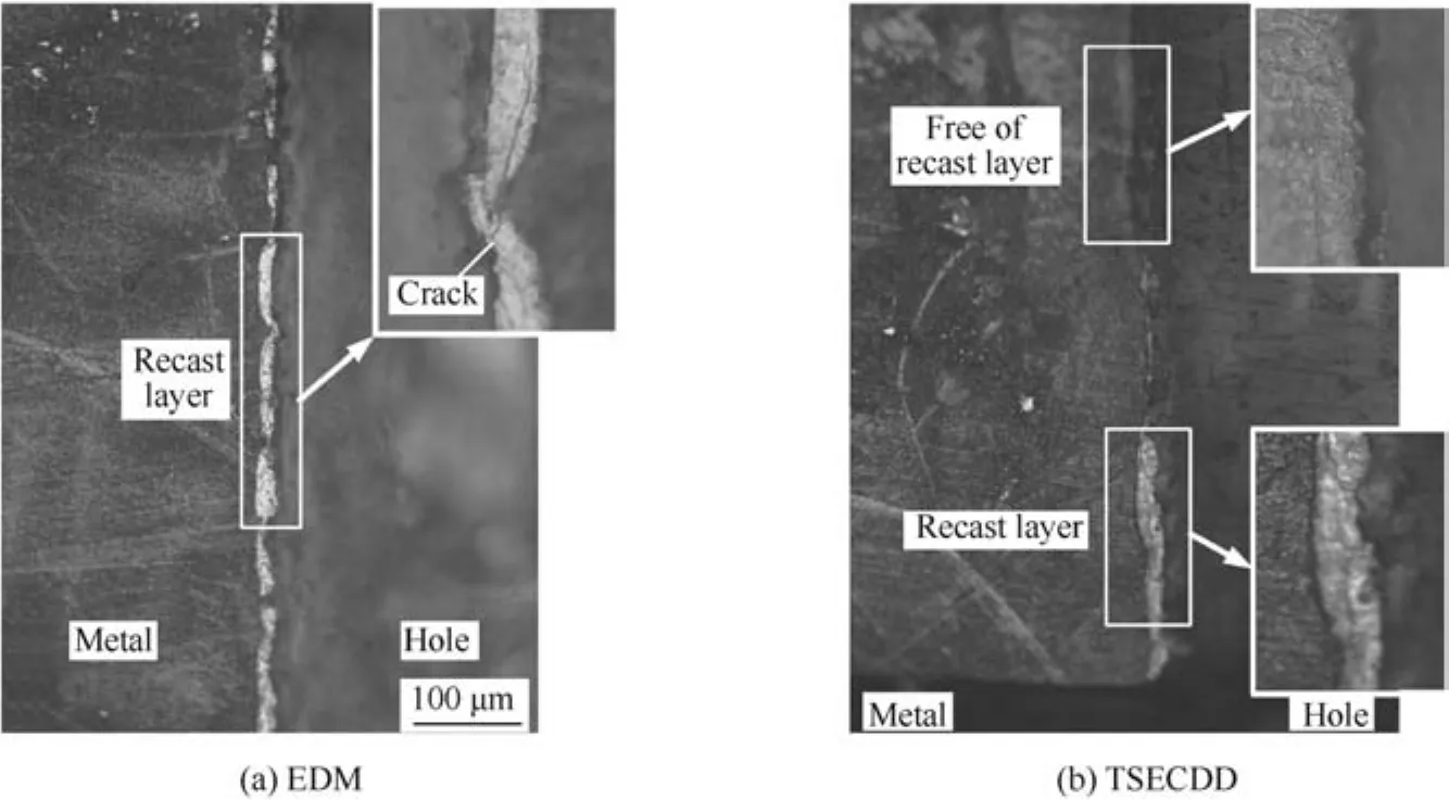
Fig.8 Recast layer in the hole surface after EDM or TSECDD.
5.Fabrication of film-cooling hole for single-crystal superalloy
The optimum machining parameters are used to fabricate a film-cooling hole.Compared with the hole formed by EDM(Fig.10(a)),the hole formed by TSECDD(Fig.10(b))clearly has a larger diameter and its edge on the rim of the entrance is also dissolved.The cross sections of the hole walls machined by EDM and TSECDD are shown in Fig.11.It can be seen that the recast layer is almost entirely removed by TSECDD,and the residual recast layer at the exit is negligible.Hence,these results validate the use of the optimum machining parameters.The single-crystal superalloy can be drilled effectively and with almost no recast layer by TSECDD.
Fig.12 compares the surfaces machined by EDM and TSECDD,and the two surfaces,which are on the same scale(500 times),come from the side wall of the hole.The figure also shows partially magnified parts of the machined surfaces.Fig.12(a)shows that in pure EDM,the machined surface is entirely covered with a re-solidified layer.In the magnified image of this layer,cracks are clearly observed in addition to voids and metal globules.The surface machined by TSECDD is shown in Fig.12(b).Compared to the EDM-machined surface,the surface quality obtained by TSECDD is remarkably better,and the entire machined area is smooth and recastfree.The magnified image shows that surface defects like cracks,voids,and metal globules are removed because of electrochemical dissolutions occurring on the surface generated by EDM.This illustrates that by using the optimum parameters,TSECDD can effectively eliminate the recast layer and achieve better surface finishing.
Further,the TSECDD results obtained using the optimum parameters are compared with the EDM results in terms of the composition of surfaces(Fig.13).In Fig.13(a),for the sample machined by EDM,it is observed that the contribution of oxygen in the composition is 5.34%.However,on the surface machined by TSECDD,no oxygen exists,as shown in Fig.13(b).This can be explained by the formation mechanism of the recast layer.During electrical discharge,the high temperatures created in the discharge channel result in the melting and vaporisation of metal;meanwhile,water decomposes into hydrogen and oxygen under high temperatures.Thus,the molten metal and oxygen rapidly combine to form an oxide layer on the machined surface.Therefore,the EDM-machined surface contains oxygen.Furthermore,as shown in Fig.13(b),there is no trace of oxygen on the surface.In addition,sodium appears on the machined surface;this can be attributed to the electrochemical reaction,during which sodium ions in the salt solution are precipitated onto the workpiece surface.Fig.13(b)also indicates that the recast layer vanishes completely from the machined surface because of the electrochemical dissolution during TSECDD.
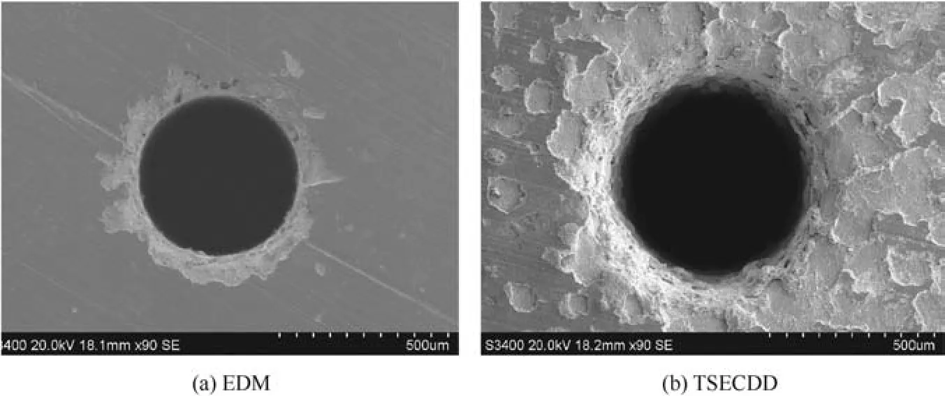
Fig.10 SEM images of micro-holes machined by EDM and TSECDD.
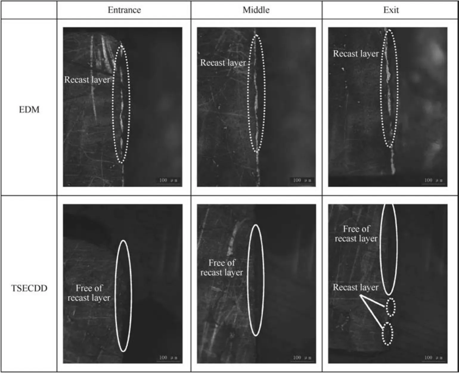
Fig.11 Metallographic microscope images of cross sections machined by EDM and TSECDD.
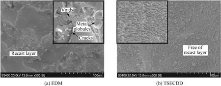
Fig.12 Comparison of surface topography obtained by EDM and TSECDD.

Fig.13 EDX spectra showing the composition of surfaces machined by EDM and TSECDD.
In Fig.13(a)and(b),the silicon and carbon elements can be found on the machined surface.As semiconductive materials,silicon and carbon elements have a weak conductivity.Relative to other metal ions in the workpiece,they are removed by the electrochemical dissolution and electrical discharge at a lower speed.In both the TSECDD and EDM processes,the removal rates of silicon and carbon elements are lower than those of the metal elements of the workpiece.Hence,there are many residual silicon and carbon elements on the side wall of the hole.Compared with the composition of DD6,the contents of silicon and carbon elements on the machined surface are relatively higher.
Moreover,it can be observed that the contribution of carbon is up to 14.66%on the machined surfaces.Under high temperatures of the discharge column,carbon debris is ejected from the workpiece material by melting and evaporation.Some debris particles may re-deposit on the surface of the workpiece and change the carbon content on the surface.However,when TSECDD instead of EDM is used,the carbon content on the machined surface decreases to 4.52%.This implies that the debris particles re-deposited on the surface are also removed.Hence,by parameteroptimisation,TSECDD can be used to obtain a single-crystal superalloy with a smooth and regular surface.
6.Conclusions
In this study,a TSECDD process is used to machine a nickelbased single-crystal superalloy(DD6).Based on the Taguchi experiment,the effects of different parameters on machining efficiency and quality are investigated,and the following conclusions are drawn:
(1)TSECDD is a promising technology for creating filmcooling holes in nickel-based single-crystal superalloys.
(2)The effects of different parameters on the machining performance are studied by performing experiments.To achieve the best performances,the following optimum parameter combination should be selected:a pulse duration of 12 μs,a pulse interval of 30 μs,a peak current of 6 A,and a solution conductivity of 3 mS/cm.
(3)A film-cooling hole is machined by TSECDD,and the TSECDD process is found to be useful for producing the hole without a recast layer.Compared to EDM,TSECDD isfound to bemorepromising for improving the surface quality and eliminating the recast layer.
Acknowledgements
The authors acknowledged the financial support provided by the NationalNaturalScience Foundation of China(No.51475237),theNationalHigh-TechResearchand Development Program of China(2013AA040101),the Program for New Century Excellent Talents in University of China(No.NCET-12-0627),and the Funding of Jiangsu Innovation Program for Graduate Education of China(No.KYLX_0232).
1.Zheng Y,Hassan I.Experimental flow field investigations of a film cooling hole featuring an orifice.Appl Therm Eng2014;62(2):766–76.
2.Lee KD,Kim KY.Film cooling performance of cylindrical holes embedded in a transverse trench.Numer Heat Transfer A(Appl)2014;65(2):127–43.
3.Yao Y,Zhang JZ,Tan XM.Numerical study of film cooling from converging slot-hole on a gas turbine blade suction side.Int Commun Heat Mass Transfer2014;52:61–72.
4.Wang W,Zhu D,Qu N,Huang S,Fang X.Electrochemical drilling inclined holes using wedged electrodes.Int J Adv Manuf Technol2010;47(9–12):1129–36.
5.Fang X,Qu N,Li H,Zhu D.Enhancement of insulation coating durability in electrochemical drilling.Int J Adv Manuf Technol2013;68(9–12):2005–13.
6.Leigh S,Sezer K,Li L,Grafton-Reed C,Cuttell M.Recast and oxide formation in laser-drilled acute holes in CMSX-4 nickel single-crystal superalloy.Proc Inst Mech Eng B J Eng Manuf2010;224(7):1005–16.
7.Fang XL,Qu NS,Zhang YD,Xu ZY,Zhu D.Improvement of hole exit accuracy in electrochemical drilling by applying a potential difference between an auxiliary electrode and the anode.J Mater Process Technol2014;214(3):556–64.
8.LiuJ,CaoJ,LinX,SongX,FengJ.Microstructureandmechanical properties of diffusion bonded single crystal to polycrystalline Nibased superalloys joint.Mater Des2013;49:622–6.
9.Burger M,Koll L,Werner EA,Platz A.Electrochemical machining characteristics and resulting surface quality of the nickel-base single-crystalline material LEK94.J Manuf Process2012;14(1):62–70.
10.Li Z,Xiong J,Xu Q,Li J,Liu B.Deformation and recrystallization of single crystal nickel-based superalloys during investment casting.J Mater Process Technol2015;217:1–12.
11.le Graverend JB,Cormier J,Gallerneau F,Villechaise P,Kruch S,Mendez J.A microstructure-sensitive constitutive modeling of the inelastic behavior of single crystal nickel-based superalloys at very high temperature.Int J Plast2014;59:55–83.
12.Sezer HK,Li L,Schmidt M,Pinkerton AJ,Anderson B,Williams P.Effect of beam angle on HAZ,recast and oxide layer characteristics in laser drilling of TBC nickel superalloys.Int J Mach Tools Manuf2006;46(15):1972–82.
13.Ruifeng S,Xiaobing Z,Wenbin C,Shuili G,Xiaopeng Z.Laser drilling of Ni-base single-crystal superalloy through thermal barrier coatings.Rare Met Mater Eng2014;43(5):1193–8.
14.Kunieda M,Mizugai K,Watanabe S,Shibuya N,Iwamoto N.Electrochemical micromachining using flat electrolyte jet.CIRP Ann–Manuf Technol2011;60(1):251–4.
15.Kawanaka T,Kato S,Kunieda M,Murray JW,Clare AT.Selective surface texturing using electrolyte jet machining.Procedia CIRP2014;13:345–9.
16.Wang CC,Chow HM,Yang LD,Lu CT.Recast layer removal after electrical discharge machining via Taguchi analysis:a feasibility study.J Mater Process Technol2009;209(8):4134–40.
17.Nguyen MD,Rahman M,San Wong Y.Simultaneous micro-EDM and micro-ECM in low-resistivity deionized water.Int J Mach Tools Manuf2012;54–55:55–65.
18.Sen M,Shan H.A review of electrochemical macro-to micro-hole drilling processes.Int J Mach Tools Manuf2005;45(2):137–52.
19.Nguyen MD,Rahman M,San Wong Y.Enhanced surface integrity and dimensional accuracy by simultaneous micro-ED/EC milling.CIRP Ann–Manuf Technol2012;61(1):191–4.
20.Zhang Y,Xu Z,Zhu D,Xing J.Tube electrode high-speed electrochemical discharge drilling using low-conductivity salt solution.Int J Mach Tools Manuf2015;92:10–8.
21.Liu DS,Zhang DX,Liang JW,Wen ZX,Yue ZF.Prediction of creep rupture life of a V-notched bar in DD6 Ni-based single crystal superalloy.Mater Sci Eng,A2014;615:14–21.
22.Jichun X,Jiarong L,Shizhong L.Surface recrystallization in nickel base single crystal superalloy DD6.Chin J Aeronaut2010;23(4):478–85.
23.Sun N,Zhang L,Li Z,Shan A.The effect of microstructure on the creep behavior of a low rhenium-containing single crystal nickelbased superalloy.Mater Sci Eng,A2014;606:175–86.
Zhang Yanis a Ph.D.student in the College of Mechanical and Electrical Engineering at Nanjing University of Aeronautics and Astronautics in China.His areas of research include electrochemical machining and electrical discharge machining.
Xu Zhengyangis a professor in the College of Mechanical and Electrical Engineering at Nanjing University of Aeronautics and Astronautics in China.He received his Ph.D.degree from the same university.His current research interests are electrochemical machining,electroforming,electrical discharge machining,and micro electrochemical machining.
4 May 2015;revised 4 June 2015;accepted 10 June 2015
Available online 28 August 2015
ⓒ2015 The Authors.Production and hosting by Elsevier Ltd.on behalf of CSAA&BUAA.This is an open access article under the CC BY-NC-ND license(http://creativecommons.org/licenses/by-nc-nd/4.0/).
*Corresponding author.Tel.:+86 25 84895912.
E-mail addresses:zhangyanzy@nuaa.edu.cn(Y.Zhang),xuzhy@nuaa.edu.cn(Z.Xu).
Peer review under responsibility of Editorial Committee of CJA.
杂志排行

CHINESE JOURNAL OF AERONAUTICS的其它文章
- Hypersonic starting flow at high angle of attack
- Advances and trends in plastic forming technologies for welded tubes
- Instability and sensitivity analysis of flows using OpenFOAM®
- Numerical simulations of high enthalpy flows around entry bodies
- Modeling and simulation of a time-varying inertia aircraft in aerial refueling
- Experimental investigations for parametric effects of dual synthetic jets on delaying stall of a thick airfoil