Static strength analysis of dragonfly inspired wings for biomimetic micro aerial vehicles
2016-11-23PraveenaNairSivasankaranThomasArthurWardRubentherenViyapuriMohdRafieJohan
Praveena Nair Sivasankaran,Thomas Arthur Ward,Rubentheren Viyapuri,Mohd Rafie Johan
Department of Mechanical Engineering,University of Malaya,Kuala Lumpur 50603,Malaysia
Static strength analysis of dragonfly inspired wings for biomimetic micro aerial vehicles
Praveena Nair Sivasankaran,Thomas Arthur Ward*,Rubentheren Viyapuri,Mohd Rafie Johan
Department of Mechanical Engineering,University of Malaya,Kuala Lumpur 50603,Malaysia
Biomimetic micro aerial vehicle;Carbon fiber;Finite element analysis;Glass fiber;Wing membrane;Wing structure
This article examines the suitability of fabricating artificial,dragonfly-like,wing frames from materials that are commonly used in unmanned aircraft(balsa wood,black graphite carbon fiber and red prepreg fiberglass).Wing frames made with Type 321 stainless steel are also examined for comparison.The purpose of these wings is for future use in biomimetic micro aerial vehicles(BMAV).BMAV are a new class of unmanned micro-sized aerial vehicles that mimic flying biological organisms(like flying insects).Insects,such as dragon flies,possess corrugated and complex vein structures that are dif ficult to mimic.Simpli fied dragon fly-like wing frames were fabricated from these materials and then a nano-composite film was adhered to them,which mimics the membrane of an actual dragonfly.Finite element analysis simulations were also performed and compared to experimental results.The results showed good agreement(less than 10%difference for all cases).Analysis of these results shows that stainless steel is a poor choice for this wing configuration,primarily because of the aggressive oxidation observed.Steel,as well as balsa wood,also lacks flexibility.In comparison,black graphite carbon fiber and red prepreg fiberglass offer some structural advantages,making them more suitable for consideration in future BMAV applications.
1.Introduction
A biomimetic micro aerial vehicle(BMAV)is a type of microscaled aircraft that mimics the flapping wing motion of insects or small birds(e.g.hummingbirds).The additional lift gained by rapidly oscillating its wings,allows BMAV to attain lift with a very small wing surface area.This also allows them to be highly agile.The US Defense Advanced Research Projects Agency(DARPA)released a Broad Agency Announcement(BAA 97-29)in 1997,defining micro aerial vehicles to be less than 15 cm in any dimension.Later in 2005,DARPA defined nano aerial vehicles(BAA 06-06)as being no larger than 7.5 cm or heavier than 10 g(carrying a 2 g payload).The primary payloads envisioned for a BMAV are ultra-lightweight,compact electronic and surveillance detection equipment.Their miniature size makes them difficult to detect,easy to quickly deploy by a single operator,relatively inexpensive tofabricate,and allows the potential to fly them inside buildings or compact spaces.BMAVs are envisioned for use on civil and military missions that are of a limited duration,such as remote sensing of hazard sites(e.g.chemical spill,radiation,high voltage power lines,etc.),indoor video mapping,and police or military surveillance.
Like the wings of a flying insect,the artificial wings of BMAV must be flexible but strong enough to endure the aerodynamic forces produced by flapping motion.During flight,the wings undergo significant bending and twisting deformations that can alter the direction and magnitude of the aerodynamic forces generated.1–5Several fabrication methods for smallinsect-scale artificialwings have been proposed.Pornsin-sirirak et al.presented the first microelectromechanical systems(MEMS)photolithography and etching method,in which the vein and membrane of the wing are fabricated using a titanium alloy(Grade 5)and parylene-C,respectively.6Combes and Daniel measured the wing flexibility of several insects and found that the spanwise flexural stiffness was one to two orders of magnitude larger than the chordwise flexural stiffness.2The scope of their investigation is limited due to the diversity in venation as well as the complex cross-sectional and planform geometries of the insect wings.In contrast,the morphology and materials of arti ficial wings can be manipulated to understand the effect of these properties on wing flexibility.Tanaka and Wood investigated the effects of flexural and torsional wing flexibilities on lift generation in hover fly flight using an insect-scaled mechanical model of an arti ficial wing.7Phan et al.created arti ficial wings that mimic the main venation structure of a beetle using prepreg carbon/epoxy fiber for the framing structure and thin Kapton film for the membrane.8Bao et al.describes the design and micromachining of a three-dimensional BMAV wing from SU-8 material using MEMS lithography.9Truong et al.created an arti ficial foldable wing that mimics the rotational motion of a beetle’s wing base using a four-bar linkage system.10Kumar et al.created an arti ficial flapping wing inspired by a hummingbird.The wing frame was fabricated from carbon fiber and a polyethylene film was laminated on this to form the wing membrane.11Ko et al.presented a micro and nano-fabrication process that mimics a realistic beetle(Atlas Dichotoma)wing having the vein–membrane structure with an anti-wetting(hydrophobic)function.A vein structure made up of titanium-alloy was constructed.A Te flon membrane was designed using a centrifugal spinning process and‘‘nanopillar forests” (like those on the surface of leaves and insect wings)were generated using a closely monitored ion treatment.The duration of ion treatment controlled the nanopillar pattern,which affected the hydrophobic characteristics of the wing created.Heat treatment was done to create superhydrophobic characteristics,bio-mimicking an actual beetle.12Cho et al.,replicated the surface nano-structure of a dragon fly wing,which has an important role in its hydrophobic characteristics.The nano-structure on a dragonfly’s wing consists of an array of nano-sized pillars(100 nm in diameter).Various substrates were used:silicon,glass,curved acrylic polymer and flexible polyethylene terephthalate(PET)film.The nano-structure was replicated using ultraviolet curable nano-imprint lithography(NIL)and polydimethylsiloxane(PDMS)molding.The hydrophobicity was measured by water-based contact angle measurements.The water contact angle of the replica made of cured polymer was 135°± 2°,which was slightly lower than that of the original dragonfly’s wing(145°± 2°).13As can be seen,most past literature involves wing membrane materials.Very little has been written about the BMAV wing frame structures that encase the membrane.
In this article we describe a novel methodology of fabricating BMAV wings(based on the Diplacodes Bipunctata dragonfly)using three materials that are commonly used in unmanned aircraft structures:balsa wood,black graphite carbon fiber and red prepreg fiberglass.These are compared to wings made from stainless steel(Type 321),which are representative of metals that have a high load bearing capacity.(In contrast,the balsa wood wings represent a lightweight,low load bearing capacity material.)
Actual dragonfly wings consist of a highly complex pattern of vein structures.It is not practical to fabricate a BMAV wing that exactly matches this complex structure.A simplified model of this wing was created using spatial network analysis.This is a method that can be used to simplify a model based on the venation pattern density.This is described in detail in another article written by the authors of this work.14The wing membrane was formed by immersing the wing frame structures in a chitosan nano-composite suspension,with chitin whiskers as a physical reinforcement and tannic acid as the crosslinking agent,using the casting evaporation method.15After 48 h of solidification a nano-composite film with a thickness of 0.03 mm was created.Finite element analysis was conducted on the simplified models of these wings and compared to tensile and bending test measurements to verify the simulation results.
2.Methodology
2.1.Wing structure overview
Fig.1 shows a comparison between the detailed vein structure models of the dragon fly wings and their corresponding simplified vein structure models.As Fig.1 illustrates dragon flies have different forewing and hindwing geometries,so both were considered.As previously described,the simpli fied models were created using spatial network analysis.14
2.2.Fabrication of wing frame structures for experiment
Several geometrically identical wings were fabricated based on the two simplified models.(These models have exactly the same planform dimensions as the actual dragonfly wing.)Although the same nano-composite was used for each wing membrane,the frames were fabricated from four different materials:stainless steel(Type 321),balsa wood,black graphite carbon fiber laminates and red prepreg fiberglass laminates.Three samples of each wing type were tested to determine their tensile strength and bending performance.The mechanical properties of these materials are as stated in Table 1 (Note:the relatively thick stainless steel wing(0.01 m)is due to a fabrication limitation with our laser cutting machine.Attempts to fabricate thinner structures failed because of melting.).The compromise between minimizing the weight and maintaining adequate tensile and bending strengths are critical for BMAV wings.

Fig.1 Models of a dragonfly wing.
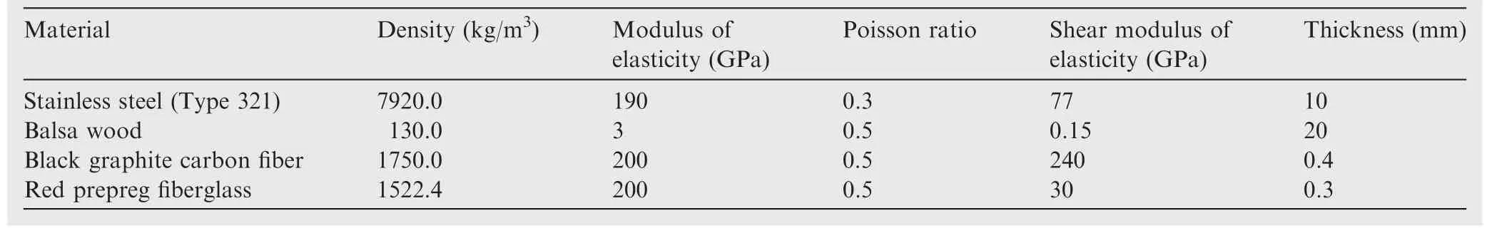
Table 1 Mechanical properties of frame structure materials.11,16–26
Stainless steel(Type 321)is in the high carbon grade category,meaning that it contains a minimum and maximum of 0.04%and 0.10%of carbon,respectively.Higher carbon helps the material retain strength at extreme temperatures.(Type 321)is commonly used in aircraft applications,because of its low density(e.g.relative light weight)and high temperature resistance.In our experiment,the stainless steel was subjected to solution annealing.This is a common process done to ensure the smoothness of the grain structure.This means only the carbides which may have precipitated to the grain boundaries are dispersed into the metal matrix by the annealing process.(Type 321)stainless steel offers higher creep and stress rupture properties.
The stainless steel wing frames were laser cut from sheet metal.These frames were then coated with an anti-rust layer and spray painted using an acrylic lacquer spray.This was necessary because the nano-composite film membrane will expose the wing frame to oxidation.This is because the film contains concentrated glacial acetic acid and tannic acid as a crosslinker.If these protective sprays are not used,oxidation will occur,visibly indicated by purple blotches appearing on the frame.After these processes,the frames were then immersed in the nano-composite suspension which formed a film membrane coating the entire wing,as previously described.Figs.2(a)and(b)show the finished stainless steel wings.
Balsa wood is the most widely-used material used in hobby remote-controlled aircraft.This is because of its extremely low density(making it very lightweight)and high mechanical strength.Balsa wood was chosen for this study because it represents a minimum weight solution.The balsa wood wing frames were cut manually with wood carving knives and then immersed into the nano-composite solution.Figs.2(c)and(d)show the finished balsa wood wings.
Black graphite carbon fiber sheets were purchased and visually inspected to make certain that they were uniform in appearance and free from foreign material.The specifications are listed in Table 2.
The woven laminate was hardened using an epoxy resin with a hardener(Araldite rapid kit).Both epoxy resin and hardener were mixed with a ratio of 1:1 and then applied evenly to the laminate in a thin layer.The laminate was then left to cure in a Memmert UNB 300 convection oven for about 2 h at a constant temperature of 45°C.The forewing and hindwing shapes were then carved out of the hardened laminates manually with a knife,using the stainless steel wings as a reference.The only difference between the black graphite wings and the others,were that the inner gap regions were not carved out according to the simplified model.Attempts to do so proved impossible,because it resulted in delamination of the material.However,the overall size and shape of these wings are the same as the others.Figs.2(e)and(f)show the finished black graphite carbon fiber wings.
Redprepregfiberglassplieswithathicknessof0.03 mmwere purchased and visually inspected.After curing,the red prepreg fiberglass exhibits a plastic-like characteristic.Unlike carbon fiber which will retain its strand-like properties.This increases the chance of delamination if a resin and hardener are not applied.The red prepreg fiberglass(after curing)does not require an extra application of resin or hardener.In order to create the wing frame structure,the material was warmed as necessary to enable easier manual carving with a knife.Figs.2(g)and(h)showthefinishedredprepregfiberglasswings.
2.3.Chitosan nano-composite solution
The chitosan nano-composite suspension as mentioned earlier was made up of a chitosan suspension reinforced with nanosized chitin whiskers and cross-linked using tannic acid.This nano-composite film was processed by our research team for this specific purpose and is featured in another article.15The suspension was transformed into a thin 3 mm film by the casting evaporation method.This film was chosen because it closely mimics the material properties of a dragonfly wing membrane.The mechanical properties and water resistivity of chitosan film can be controlled by the addition of chitin whiskers and tannic acid as a cross-linker.Utilizing nanosized whiskers as a filler material elevates the composite film’s mechanical property(rigidity).A cross-linking agent is also added to alter the mechanical properties of the film created.Tannic acid is fully biodegradable and less expensive to produce,compared to the other chemical derivatives.Tannic acid also has a high antioxidant capacity and can interact with other biological macro-molecules.Addition of tannic acid as a cross-linking agent reduces the swelling behavior,solubility and rigidity of the nano-composite film.In order to ensure that the immersion is uniform,the structure was submerged in the solution.This also ensures that both sides of the frame structure are evenly coated with the solution.Once cured,the film created a shiny,transparent film layer that adheres firmly to the frame structure.

Fig.2 Fabricated wing frames.

Table 2 Specifications of black graphite carbon fiber.

Fig.3 Carbon fiber yarn waviness.
2.4.Simulation setup
A three-dimensional solid model was constructed using the Rhinoceros 5.0 computer aided design(CAD)software.This was then exported to AutoCad 2015.Autodesk Simulation Multiphysics software(2013 version)was used to perform the finite element analysis(FEA)of this model.Since the physical wing models were subjected to tensile and bending tests,the same conditions and constraints(used in these experiments)were input into the software in order to allow comparison between the measured and simulated results.
2.4.1.Finite element analysis
The general structural equation used by Autodesk FEA software is shown in Eq.(1).

where M is the mass matrix,U the displacement vector,C the damping matrix,K the stiffness matrix,F the force vector,Athe area andrthe number of nodes.An important consideration when performing finite element analysis is to ensure that the model is properly meshed.In the present study,the mesh sizes of the elements were viewed visually to ensure that the mesh distribution is fine throughout the structure.The mesh size used for the dragonfly wing and the corresponding models are 0.001 m.The mesh was chosen based on the results of a grid study which gave a percentage difference of about 3%between the fine and coarse mesh.Shell-based elements are often used in finite element analysis models to calculate the displacement.Each element in this model was specified as a shell,in order to simulate the highly efficient load bearing capabilities of an insect wing.Autodesk’s algebraic iterative multi-grid scheme,with a third order Newton Raphson integration method,was used as the finite element solver.A general element formulation was selected,because this provides a robust solution for thin and thick elements.This was necessary because the wing model is designed with two different types of thickness(vein and membrane).The analysis formulation is set to static stress analysis.The shell element model is set to be isotropic.
2.4.2.Static stress analysis
A fixed constraint was placed at the base of the wing tip to mimic the hinge of an actual dragonfly wing.Nodal forces were applied at the tip of the wing to mimic the tensile and bending test experiments.Simulations were done for all eight wings(forewing and hindwing fabricated from all four materials).In addition,simulated bending and tensile tests were done for the frame structures without the membrane to record the effects of the chitosan nano-composite film on the frame structure.The stresses computed in the static analysis are used to form thestress-dependentcontribution to thetangentstiffness matrix.Static stress analysis enables the study of stress,strain,displacement,and shear and axial forces that result from static loading.
2.5.Experimental setup
Tensile and bending experiments were done on the physical models using the Instron Universal Testing Machine(Model 5569).Increasing loads were incrementally applied to the wings until they failed.The data was compiled and integrated by Instron MERLIN software.A specific jig was designed for both bending and tensile tests to clamp the fabricated models,whereby the slots were used to clamp the thin structures firmly.All testing was repeated three times for each wing type,necessitating the fabrication of three identical copies of each wing type.Average measurements of the three tests of identical wings are shown in the figures located in Sections 3.3 and 3.4(The standard deviations of all these tests are less than 2%,which was too small to plot as error bars on the figures.).Since the wing frame test specimen is a sheet-like structure the same ratio of width-to-gage length(18:18 for forewing and 20:20 for hindwing)was maintained in order to compensate for the elongation that occurs during diffuse necking.ASTM test specifications were followed throughout the experiment.Each base of the wing models were clamped at a fixed point and the tips were clamped at the moving point.The load was then increased gradually with a speed rate of 0.013 m/s.The rate of extension and the stress–strain curve were observed until the wing model experienced a structural failure.This point can be observed in the collected data as a sudden decrease in the load.Data obtained in RAW file was then converted to Microsoft Excel for further analysis.
3.Results and discussion
3.1.Tensile test simulation results
Simulation results were obtained before the experiments were conducted.Both tensile and bending tests were analyzed and the stress distribution was observed.Simulation tensile test results were observed and critical or high stress areas were marked as point of fractures.These results helped in identifying the weak areas(regions)of the wing models of different materials and the maximum stress that the models could withstand.
3.1.1.Tensile simulations of wing frames without membranes
The first experiments involved the wing frame structures without their membranes(The material specifications for these models are stated in Table 1).Fig.4 shows the von Misses stress results of all the four different frame structures.The‘max’(maximum)and ‘min’(minimum)pointers indicate the area where the stress is the highest.The highest stress in the forewing recorded for stainless steel(Type 321),balsa wood,black graphite carbon fiber and red prepreg fiberglass is 2.54,0.04,2.03 and 0.03 N/mm2,respectively.A close observation from the results shows that the high stress point for all four materials,except the balsa wood,occurs in the same region.This region is located where the surface-to-area ratio is at its minimum value.Maximum stress on the balsa wood wing occurred at the grip point.Based on previous studies,21balsa wood,under compression in the axial direction exhibits a linearly elastic regime that terminates by the initiation of failure in the form of localized kinking.Geometric imperfections in the form of fiber waviness and failure were found to lead to kink bands with distinct orientations and widths.27Subsequently,under displacement-controlled compression,a stress plateau is traced that is associated with the gradual spreading of crushing of the cells through the material.The material is less stiff(i.e.weaker)in the tangential and radial directions.Compression in these directions crushes the tracheids(phloem of the wood)laterally.Fig.5 shows the results for the hindwing.The maximum stress occurs in approximately the same location for all the wing frame structures.This region corresponds with the minimum surface-to-area ratio.The minimum stress also occurs in a similar location for all of the wing frames,except for the balsa wood frame.The readings are 2.31,0.08,1.39 and 0.02 N/mm2for stainless steel(Type 321),balsa wood,black graphite carbon fiber and red prepreg fiberglass,respectively.The minimum stress for the balsa wood frame occurs in the cambered edge,because it experiences the lowest compression stress.This has been observed for balsa wood in the previous studies.20,21,23,24
3.1.2.Tensile simulations of wing frames with membranes
Simulation results were also obtained for the wing frames with their membranes.Figs.6 and 7 show the forewing andhindwingmodelsofallfourmaterials.Based on Fig.6,the maximum von Misses stress occurs at approximately the same location for all four materials.This location is different from the models without membranes(see Fig.4).However,the highest stresses occur again in regions where the surface-to-area ratio is minimum.An exception is seen in the wing frame made of black graphite carbon fiber laminate,where the maximum stress occurs in the cambered edge of the wing.This is due to the fact that carbon fiber undergoes delamination at areas where the kinks and curves are located.28The region where maximum stress occurs shows a potential area of delamination.The maximum stress recorded is 2.05,0.097,49.3 and 2.10 N/mm2for stainless steel(Type 321),balsa wood,black graphite carbon fiber and red prepreg fiberglass,respectively.
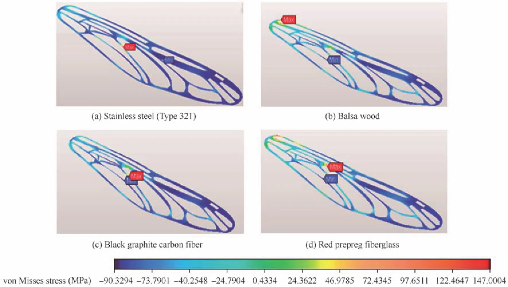
Fig.4 von Misses stress simulation results of different forewing frame structures(without membrane,tensile test).
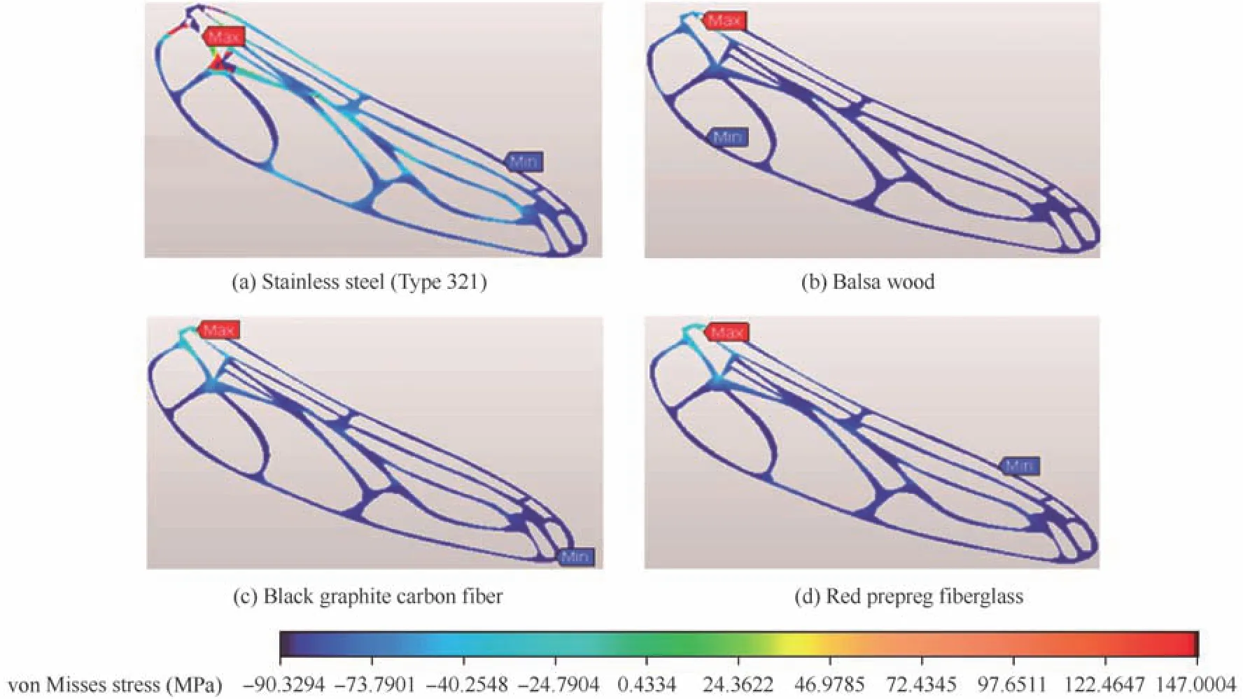
Fig.5 von Misses stress simulation results of different hindwing frame structures(without membrane,tensile test).
3.2.Bending test simulation results
3.2.1.Bending simulations of wing frames without membrane
Some of the wing frames without membrane were subjected to bending tests.Only the steel and balsa wood frame structures were subjected to this bending test.Attempts to conduct bending tests on the red prepreg fiberglass and wing frame structures of black graphite carbon fiber laminates gave trivial results.These materials do not fail when subjected to bending experiments.29Therefore,the simulation results for black graphite carbon fiber and red prepreg fiberglass laminates were not included.
Figs.8 and 9 show the von Misses stress simulation results for the forewing and hindwing structures.The bending test results show uniformity in the stress distribution of all four frame structures for both forewing and hindwing.The maximum stress occurred in the same relative region for all four different frame structures,regardless of the wing type.This shows that bending creates a localized stress in both of the materials used.Combes et al.found that the flexural stiffness across the wing base line is maximum when it is subjected to bending.2,3The hinge of a dragonfly wing must be able to withstand different types of loads,including forces subjected to rotational and translational motion.Hence the maximum stress occurred at the region near the wing base(where the pivot point is located),as highlighted in the simulation results.The maximum bending stress for forewings of stainless steel and balsa wood is 0.80 and 0.11 N/mm2,respectively.The hindwing maximum stress was 0.64 and 0.05 N/mm2for stainless steel and balsa wood,respectively.
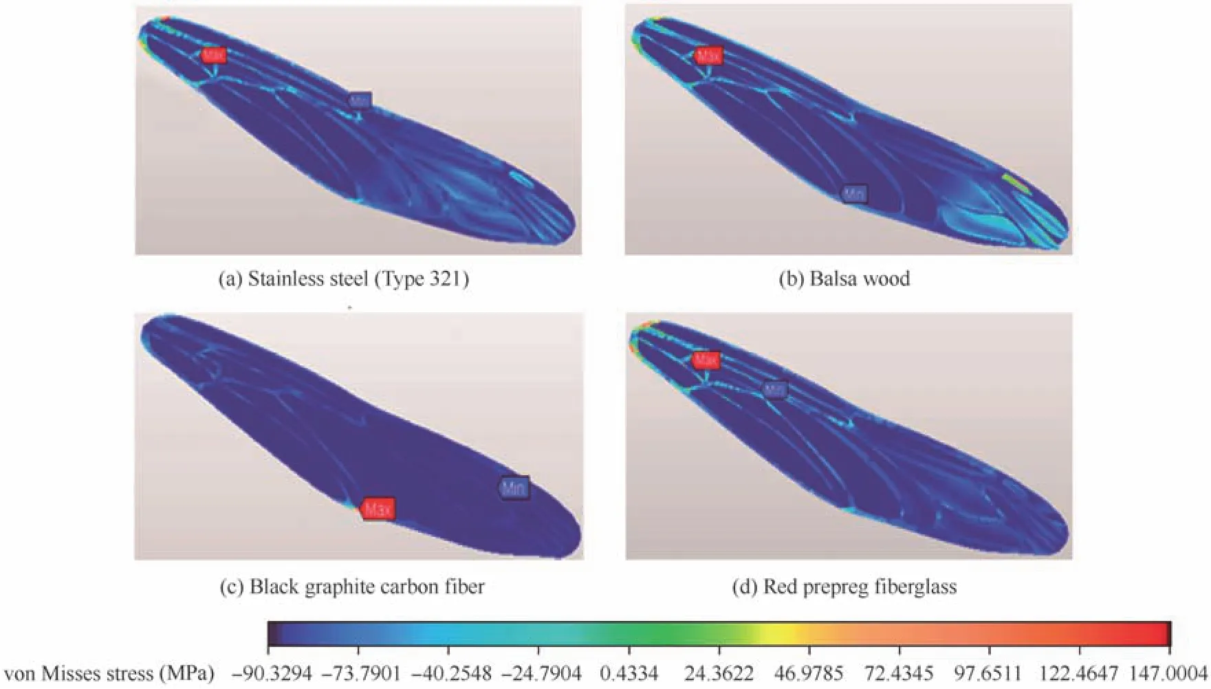
Fig.6 von Misses stress simulation results of different forewing model structures(with membrane,tensile test).
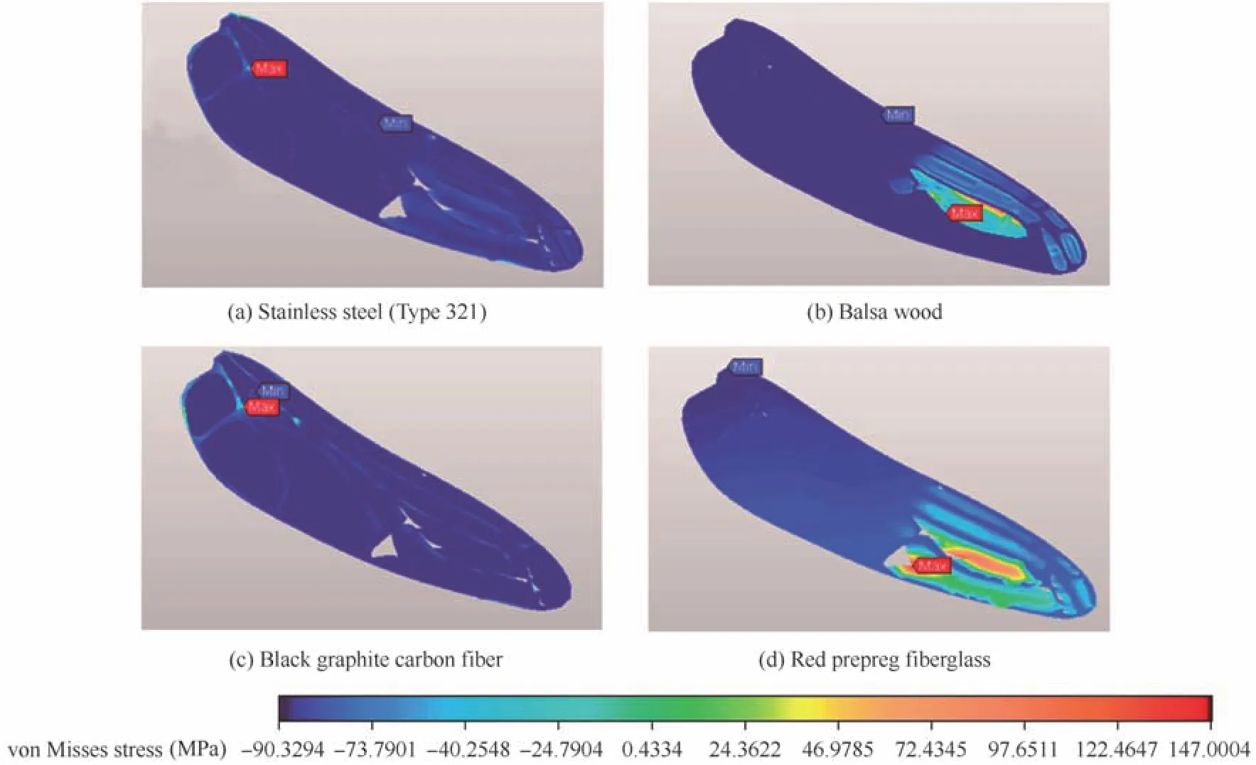
Fig.7 von Misses stress simulation results of different hindwing model structures(with membrane,tensile test).
3.2.2.Bending simulations of wing frames with membrane
Figs.10 and 11 show the bending stress created on the wing frames with their membrane.The results show that the tips of the wings undergo damage faster than the base of the wing.The figures also indicate that there is a greater probability of the membrane undergoing damage than the frame structure.The region where the tip of the wing undergoes bending deformation matches previous studies that have been conducted.30–33The von Misses stress for the hindwing is 2.09 and 0.09 N/mm2for stainless steel and balsa wood respectively.However,only these results clearly show the effects of the bending load on the membrane of an artificial dragonfly wing.
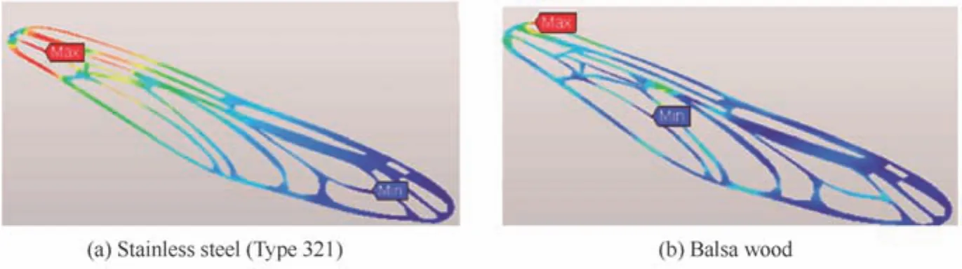
Fig.8 von Misses stress simulation results of different forewing model structures(without membrane,bending test).

Fig.9 von Misses stress simulation results of different hindwing model structures(without membrane,bending test).
3.3.Tensile test results
In Figs.12 and 13,we compare the forewing and hindwing for all four different frame structure materials.We also compare the results of models with and without membranes,allowing the effects of the chitosan film on the frame structures to be observed.All four materials(without membrane)exhibit their original properties under tensile stress,which agrees with previous studies.11,20–26,28Both figures show a sudden decline in tensile stress,which indicates that failure(fracture)has occurred(destructive testing).In Fig.12(a),we compare the steel forewing with and without membrane.The maximum load(at failure)applied on the steel forewing was 752.98 and 2367.47 N(with and without membranes,respectively).The steel hindwing failed at 679.01 and 716.70 N(with and without membranes,respectively).The ultimate strength of the steel forewing with its membrane is 2.10 MPa and that without membrane is 2.48 MPa.These values are 2.20 MPa with membrane and 2.45 MPa without membrane for the hindwing.These results show that the addition of the film membrane causes an 8%reduction of strength for the steel wing.The chitin nano-composite membrane solution oxidizes the stainless steel wing frame.We observed aggressive oxidation in our samples,even though precautions were taken to avoid it.Therefore,it can be concluded that adhesion of the film membrane to the stainless steel reduces its overall stress resistance and increases its oxidation.Therefore,stainless steel is a poor choice of material for the wing frame,when desiring to use a chitin nano-composite film wing membrane.Referring to Figs.6(a)and 7(a),the percent difference between the simulation and experiments are approximately 4.0%and 3.52%,with and without membranes,respectively.The simulation results do not take into count the decrease of strength caused by chemical degradation.
Figs.12(b)and 13(b)show a comparison of balsa wood with and without membrane for both fore and hindwings.In contrast to stainless steel,the membrane reduces the stress acting on the balsa wood wing frame.The maximum load(at failure)of wood forewing was 60.02 and 26.85 N(with and without membrane,respectively).The wood hindwings failed at 59.54 and 58.91 N(with and without membrane,respectively).The ultimate strength of the balsa wood forewing,with and without membrane,is 0.09 and 0.03 MPa,respectively.The results of the hindwing,with and without membrane,were0.09and 0.04 MPa,respectively.This equates to an increase in ultimate strength that ranges from 125%to 200%.Therefore it can be concluded that adhesion of the chitosan nano-composite film to the balsa wood increases its strength tremendously.Referring to Figs.6(b)and 7(b),the percent difference between the simulation and experiments are approximately 6.23%and 4.56%,with and without membranes,respectively.
Figs.12(c)and 13(c)show a comparison of carbon fiber wings,with and without film membranes.The adhesion of chitosan nano-composite film yields an immense increase in strength.The maximum load(at failure)applied to carbon fiber forewings was 580.60 and 148.46 N(with and without membranes,respectively).The carbon fiber hindwings failed at 600.49 and 148.46 N(with and without membrane,respectively).The peak tensile strength for the forewings,with and without membranes,are 48.07 and 1.32 MPa,respectively.The results for the hindwings,with and without membranes,are 40.06 and 1.34 MPa,respectively.This shows that the addition of film increases the ultimate strength by 2976%to 3592%,which further shows that the adhesion of the film to these carbon fiber models greatly intensi fies its ultimate strength.Referring to Figs.6(c)and 7(c),the percentage differences between the simulation and experiments are approximately 5.23%and 3.87%,with and without membranes,respectively.

Fig.10 von Misses stress simulation results of different forewing model structures(with membrane,bending test).

Fig.11 von Misses stress simulation results of different hindwing model structures(with membrane,bending test).
Figs.12(d)and 13(d)show the results obtained for red prepreg fiberglass model wings.These results also show an increase in ultimate strength after adhesion of the chitosan nano-composite film.The maximum load(at failure)for red prepreg fiberglass forewings was 14.39 and 0.51 N(with and without membrane,respectively).The fiberglass hindwings failed at 21.34 and 0.62 N(with and without membrane,respectively).The ultimate strength for the forewing,with and without membranes,is 2.03 and 0.01 MPa,respectively.The ultimate strength for the hindwings,with and without membranes,is 3.04 and 0.01 MPa,respectively.However,the red fiberglass undergoes warping and shrinkage at a very early stage of the experiment(1 min after starting the experiment).So this phenomenon must be taken into consideration when considering this material for fabrication purpose.Referring to Figs.6(d)and 7(d),the percent differences between the simulation and experiments are approximately 5.75%and 8.93%,with and without membranes,respectively.
3.4.Bending test results
Figs.14 and 15 show the compression stress vs strain of the wing models made of stainless steel and balsa wood,respectively.Figs.13 and 14 showed a reduction in the ability of the wing frame to undergo tension when the film membrane is adhered to the stainless steel.However,this testing shows that its resistance to compression is higher in the wing models with film.Figs.14(a)and 15(a)show results for the stainless steel frames,both the forewing and hindwing.The peak strength is 2.02 MPa with membrane and 0.75 MPa without membrane.This is an increase of 167%.The hindwings are 2.03 and 0.63 MPa,with and without membrane,respectively.This is an increase of 140%.Referring to Fig.9,the percent difference between the simulation and experiments are approximately 9.97%and 8.74%,with and without membranes,respectively.
Figs.14(b)and 15(b)show the results for the balsa wood frame structures.The peak strength for the forewing structure,with and without membrane,is 0.08 and 0.04 MPa,respectively.The hindwings are 0.08 and 0.04 MPa,with and without membrane,respectively.This is an increase of approximately 200%for both balsa wood fore and hindwings.Referring to Fig.11,the percent difference between the simulation and experiments are approximately 6.49%and 7.77%,with and without membranes,respectively.

Fig.13 Tensile stress vs tensile strain(engineering)of all four hindwing frame structures.
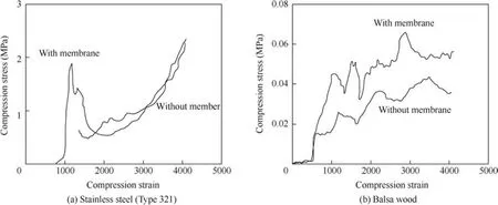
Fig.14 Compression stress vs compression strain of forewing wing models.
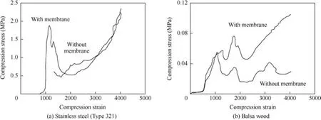
Fig.15 Compression stress vs compression strain of hindwing models.
4.Conclusions
(1)Both FEA simulations and experiments were performed and all of the results show good agreement(less than 10%difference).
(2)Experiments with steel wing frames show that the addition of the film reduces its tensile resistance and causes aggressive oxidation.Steel is also relatively heavy making it a poor choice for this application.
(3)Film adhered to a balsa wood wing frame increases its tensile strength by 125%–200%,while the peak bending strength is improved by about 200%.
(4)Both steel and balsa wood is relatively inflexible compared to the other two materials(black graphite carbon fiber and red prepreg fiberglass).
(5)Black graphite carbon fiber shows a remarkable load bearing capacity and its lightweight property makes it suitable for BMAV applications.The peak tensile strength for the forewings,with and without membranes,are 48.07 and 1.32 MPa,respectively.The results for the hindwings,with and without membranes, are 40.06 and 1.34 MPa, respectively.Addition of the film increases the ultimate strength by 2976%–3592%.
(6)The primary disadvantage of black graphite carbon fiber is the practical difficulties involved in carving it into the simplified wing frame structure.
(7)Red prepreg fiberglass mimics the elasticity and flexibility of an actual dragonfly wing structure.Results show an increase in ultimate strength after adhesion of the chitosan nano-composite film.The ultimate strength for the forewing,with and without membranes is 2.03 and 0.01 MPa,respectively.The ultimate strength for the hindwings,with and without membranes,is 3.04 and 0.01 MPa,respectively.
(8)The primary drawbacks in using red prepreg fiberglass is that it undergoes warping and rapid shrinkage.The load bearingcapacityisalso low compared to other materials.
(9)The results from these experiments will be used for future research and design of BMAV wings.
Acknowledgments
This research was done under the auspices of the Centre for Transportation Research at the Faculty of Engineering,University of Malaya.It is primarily funded by High Impact Research Grant UM.C/625/1/HIR/MOHE/ENG/53(H-16001-D000053)along with a secondary grant from the University of Malaya:RG155-12AET.
1.Combes SA.Materials,structure,and dynamics of insect wings as bioinspiration for MAVs.Encyclopedia of Aerospace Engineering:Vol.7,Part 34.3rd ed.New York:John Wiley and Sons;2010.
2.Combes SA,Daniel T.Flexural stiffness in insect wings I.Scaling and the influence of wing venation.J Exp Biol2003;206(17):2979–87.
3.Combes SA.Flexural stiffness in insect wings II.Spatial distribution and dynamic wing bending.J Exp Biol2003;206(17):2989–97.
4.Combes SA,Daniel T.Into thin air:contributions of aerodynamic and inertial-elastic forces to wing bending in the hawkmoth Manduca sexta.J Exp Biol2003;206(17):2999–3006.
5.Shang JK,Combes SA,Finio BM,Wood RJ.Artificial insect wings of diverse morphology for flapping-wing micro air vehicles.Bioinspiration Biomimetics2009;4(3):036002.
6.Pornsin-sirirak TN,Tai YC,Nassef H,Ho CM.Titanium-alloy MEMS wing technology for a micro aerial vehicle application.Sens Actuators:A2001;89(1–2):95–103.
7.Tanaka H,Wood RJ.Fabrication of corrugated artificial insect wings using laser micromachined molds.J Micromech Microeng2010;20(7):075008.
8.Phan HV,Nguyen QV,Truong QT,Van Truong T,Park HC,Goo NS,et al.Stable vertical takeoff of an insect-mimicking flapping-wing system without guide implementing inherent pitching stability.J Bionic Eng2012;9(4):391–401.
9.Bao XQ,Dargent T,Grondel S,Paquet JB,Cattan E.Improved micromachining of all SU-8 3D structures for a biologicallyinspired flying robot.Microelectron Eng2011;88(8):2218–24.
10.Truong QT,Argyoganendro BW,Park HC.Design and demonstration of insect mimicking foldable artificial wing using four-bar linkage systems.J Bionic Eng2014;11(3):449–58.
11.Kumar D,Shah M,Mohite PM,Kamle S.Structural dynamic analysis of bioinspired carbon fibre/polyethylene MAV wings.Recent Adv Mech Eng2014;3(4):7–15.
12.Ko JH,Kim J,Hong J,Yoo Y,Lee Y,Jin T,et al.Micro/nanofabrication for a realistic beetle wing with a superhydrophobic surface.Bioinspiration Biomimetics2012;7(1):016011.
13.Cho JY,Kim G,Kim S,Lee H.Replication of surface nanostructure of the wing of dragonfly(Pantala Flavescens)using nano-molding and UV nanoimprint lithography.Electr Mater Lett2013;9(4):523–6.
14.Nair P,Ward TA.Spatial network analysis to construct simplified wing structural models for biomimetic micro air vehicles.Aerosp Sci Technol2016;49:259–68.
15.Rubentheren V,Ward TA,Chee CY,Tang CK.Processing and analysisofchitosan nanocompositesreinforced with chitin whiskers and tannic acid as a crosslinker.Carbohydr Polym2015;115:379–87.
16.Akın D,Kasgoz A,Durmus A.Quantifying microstructure,electrical and mechanical properties of carbon fiber and expanded graphite filled cyclic olefin copolymer composites.Compos A Appl Sci Manuf2014;60:44–51.
17.The Boeing Company.Boeing material specification:glass fabric reinforcements for laminated plastic products.Chicago(IL):The Boeing Company;2000.
18.The Boeing Company.Boeing material specification;glass fabric preimpregnated epoxy resin low temperature curing.Chicago(IL):The Boeing Company;2003.
19.The Boeing Company.Boeing material specification:carbon fiber reinforcements,yarn and fabric.Chicago(IL):The Boeing Company;2004.
20.Borrega M,Gibson LJ.Mechanics of balsa(Ochroma pyramidale)wood.Mech Mater2015;84:75–90.
21.Da Silva A,Kyriakides S.Compressive response and failure of balsa wood.Int J Solids Struct2007;44(25–26):8685–717.
22.Leban MB,Tisu R.The effect of TiN inclusions and deformationinduced martensite on the corrosion properties of AISI 321 stainless steel.Eng Fail Anal2013;33:430–8.
23.Osei-Antwi M,De Castro J,Vassilopoulos AP,Keller T.Shear mechanical characterization of balsa wood as core material of composite sandwich panels.Constr Build Mater2013;41:231–8.
24.Osei-Antwi M,De Castro J,Vassilopoulos AP,Keller T.Fracture in complex balsa cores of fiber-reinforced polymer sandwich structures.Constr Build Mater2014;71:194–201.
25.Warren AD,Harniman RL,Collins AM.Comparison between magnetic force microscopy and electron back-scatter diffraction for ferrite quantification in Type 321 stainless steel.Ultramicroscopy2015;148:1–9.
26.Kyriakides S,Arseculeratne R,Perry EJ,Liechti KM.On the compressive failure of fiber reinforced composites.Int J Solid Struct1995;32(6–7):685–738.
27.Leckey C,Roberts R,Margetan F,Evaluation CFD.Carbon fiber composites.Ames(IA):Iowa State University;2015.
28.Babukiran BV,Harish G.Influence of resin and thickness of laminate on flexural properties of laminated composites.Int J Eng Sci Innovative Technol2014;3(1):1–9.
29.Ren HH,Wang XS,Chen YL,Li XD.Biomechanical behaviours of dragonfly wings:relationship between configuration and deformation.Chin Phys B2012;21(3):034501-1–034501-10.
30.Ren HH,Wang XS,Chen YL,Li XD.Effects of dragonfly wing structure on the dynamic performances.J Bionic Eng2013;10(1):28–38.
31.Wakelling JM,Ellington CP.Dragonfly flight:velocities,accelerations and kinematics of flapping flights.J Exp Biol1997;200(3):557–82.
32.Sun J,Bhushan B.The structure and mechanical properties of dragonfly wings and their role on flyability.CR Mec2012;340(1):3–17.
33.Jongerius SR,Lentink D.Structural analysis of a dragonfly wing.Exp Mech2010;50(9):1323–34.
8 July 2015;revised 30 October 2015;accepted 5 December 2015
Available online 23 February 2016
ⓒ2016 Chinese Society of Aeronautics and Astronautics.Published by Elsevier Ltd.This is an open access article under the CC BY-NC-ND license(http://creativecommons.org/licenses/by-nc-nd/4.0/).
*Corresponding author.Tel.:+60 3 79674455.
E-mail address:DrTomWard@um.edu.my(T.A.Ward).
Peer review under responsibility of Editorial Committee of CJA.
Thomas Arthur Wardis a Senior Research Fellow and Ph.D.supervisor in the Department of Mechanical Engineering at the University of Malaya,Kuala Lumpur,Malaysia.He received a Ph.D.degree in Mechanical Engineering from the University of Dayton(US)in 2003,MScdegreein AerosystemsEngineeringfrom Loughborough University(U.K.)in 1995,MSc degree in Aerospace Engineering from the University of Dayton in 1993,and a BSc degree in Aerospace Engineering at the University of Cincinnati(US)in 1989.He is currently the principal investigator of research on biomimimetic micro aerial vehicles.
杂志排行
CHINESE JOURNAL OF AERONAUTICS的其它文章
- Hypersonic starting flow at high angle of attack
- Advances and trends in plastic forming technologies for welded tubes
- Instability and sensitivity analysis of flows using OpenFOAM®
- Numerical simulations of high enthalpy flows around entry bodies
- Modeling and simulation of a time-varying inertia aircraft in aerial refueling
- Experimental investigations for parametric effects of dual synthetic jets on delaying stall of a thick airfoil