Crashworthiness analysis of aircraft fuselage with sine-wave beam structure
2016-11-23RenYiruXiangJinwuZhengJianqiangLuoZhangping
Ren Yiru,Xiang Jinwu,Zheng Jianqiang,Luo Zhangping
aCollege of Mechanical and Vehicle Engineering,Hunan University,Changsha 410082,China
bSchool of Aeronautic Science and Engineering,Beihang University,Beijing 100083,China
cBeijing Aeronautical Science and Technology Research Institute of COMAC,Beijing 102211,China
Crashworthiness analysis of aircraft fuselage with sine-wave beam structure
Ren Yirua,*,Xiang Jinwub,Zheng Jianqiangc,Luo Zhangpingb
aCollege of Mechanical and Vehicle Engineering,Hunan University,Changsha 410082,China
bSchool of Aeronautic Science and Engineering,Beihang University,Beijing 100083,China
cBeijing Aeronautical Science and Technology Research Institute of COMAC,Beijing 102211,China
Aircraft;Crashworthiness;Energy absorption structure;Sine-wave beam;Strut
An integrated design concept for crashworthy fuselage using sine-wave beam and strut is proposed and investigated.The finite element model of aircraft fuselage is built first.The structures above cabin floor,occupant and seat are simplified as two rigid blocks.The fuselage frame is redesigned,and the sine-wave beam is arranged under the frame.The impact dynamic performance of the aircraft with bottom sine-wave beam structure is studied and compared with that of conventional type.To obtain better crashworthiness performance,different rigidity of strut is combined with the sine-wave beam bottom structure.Numerical simulation result shows that the proposed sine-wave beam bottom structure could not only dissipate more proportion of impact kinetic energy but also reduce the initial peak acceleration.The structure and rigidity of strut have great influence on the crashworthiness performance.To give a better fuselage structure,both of the strut and bottom structure should be properly integrated and designed.
1.Introduction
The crashworthiness is one of the most important structural design requirement of aircraft in airworthiness regulations,which has attracted more and more attention for the safety of occupant.1–3To evaluate the impact dynamic performance of fuselage,the drop test of Boeing 737-200 aircraft was conducted at FAA William J.Hughes Technical Center,and the numerical simulation of fuselage using LS-DYNA nonlinear explicit software was conducted.4The simulation of aircraft crashworthiness is a time-consuming process for the detailed numerical model and transient dynamic analysis.To design a crashworthy fuselage with cost-effective approach,a novel scale modeling method is proposed by Lankarani et al.5The progresses in experimental and numerical simulation technology guarantee the feasibility of crashworthy design for aircraft.
The crashworthy fuselage could dissipate impact kinetic energy by energy absorption structure during impact process,and the acceleration suffered by the occupant and living space should be guaranteed.A number of energy absorptionconcepts including the formable keel web with foam,sandwich,corrugated sub-floor and longitudinal cylinders for light-weight aircraft and helicopter are exhibited by Crankhite and Berry.6The crashworthiness design of the transport aircraft is different from that of light-weight aircraft and helicopter.The stable supporting platform and effective energy absorption structure are the two greatest challenging design concepts for the transport aircraft.7A hexagonal honeycomb energy absorption device is introduced into sub-floor structure with scaled model by Yang et al.8To make the best of Rohacell-31 polymer foam,closed-cell blocks are adopted as the sub-floor structure to enhance energy absorption ability and mitigate peak acceleration.9The sine-wave beam is a kind of high efficiency energy absorption structure which has great potential application prospect in the crashworthy fuselage.10To utilize its energy absorption ability,the sine-wave beam with triggers is adopted at the lateral position,but the prospect failure doesn’t appear due to the lack of lateral support.11,12The sine-wave beam also could be adopted as the bottom fuselage structure,and it is used as the energy absorption structure along the longitudinal direction by David13and Huey14et al.The progressive failure is theoretically expected,but the subcargo beam located above the sine-wave beam ruptures due to the large impact load.The crashworthy design using the sine-wave beam is studied by Xiang et al.15However,the aircraft consists of many different kinds of components including the bottom structure,frame,skin,strut and stringer.The crashworthy design of fuselage is extremely difficult for the complicated impact dynamic performance of components and the coupling effect among different components during impact process.Therefore,to obtain better crashworthy fuselage structure,the integrated design concept of bottom sinewave beam structure and other components should be further considered.The strut is the support structure under the cabin floor,and it would affect the crashworthiness performance of aircraft fuselage.16,17To utilize the energy absorption ability of strut,some innovative structure is adopted.18,19From the previous research results,both of bottom structure and strut have great in fluence on the crashworthiness of aircraft,but the interaction effect between the two components is not clear.Therefore,the design concepts of strut and bottom energy absorption structure are investigated here.
To improve the crashworthiness of transport aircraft,a novel aircraft fuselage with sine-wave beam is investigated and compared.In addition,to investigate the roles of strut and bottom structure during impact accident,several different kinds of strut types combined with the sine-wave beam bottom structure are studied.The finite element method is adopted because it is popular for solving the impact dynamic problem.The reliable finite element model is built,and the crashworthiness of different design concepts is compared.The numerical simulation result is given to provide guidance for aircraft design.
2.Finite element model
The geometrical model of aircraft fuselage with the sine-wave beam is exhibited in Fig.1(a),and it is composed of cabin floor,strut,frame,cargo floor,skin,under- floor beam,sine-wavebeam,stringer,etc.Theoccupant,seatand structure above the cabin floor have little in fluence on the crashworthiness of aircraft,and they are simplified as two rigid blocks symmetrically distributed on the cabin floor.The joint,stiffener and rivet are ignored for the global impact dynamic performance is paid great attention to,and their weight is allocated to the adjacent structures.The rigid floor is adopted as the impact ground.
Based on the geometrical model,the finite element model of aircraft is built(see Fig.1(b)).The quadrilateral elements are the primary type of finite element model,and hexahedral elements are adopted to simulate occupant and seat.The elements which suffered large plastic deformation,such as the strut,frame and cargo floor,are simulated with Hughes–Liu shell theory,and other elements are based on Belytschko-Lin-Tsay shell and C0 triangular shell theory to improve computational efficiency.The contact,boundary condition and friction are properly defined to better simulate physical impact event.

Fig.1 Geometrical model and finite element model of aircraft fuselage.
The material of aircraft fuselage is Al2024 and Al7075.Al2024 is utilized as the material of skin,cargo floor and cabin floor,while other fuselage components including frame and strut are made of Al7075.The bi-linear elastic plastic material model is employed to simulate the metal structural material.The maximum plastic strain and von Mises stress are employed as the material failure criterion and yield model.The impact process is greatly influenced by the element failure,and the element would be removed if the strain reaches the maximum plastic strain for the finite element method.The yield stress is a function with respect to initial yield stress,plastic hardening modulus and effective plastic strain.
In order to guarantee the reliability and accuracy of numerical simulation result,several methods are adopted during the modeling and validation process.Firstly,the triangular element,and pentagonal and tetrahedral solids are avoided because they are too stiff.The shell element is popularly used because the thin-walled structure is the common component of aircraft.To reduce the hourglass energy,it is checked after the numerical simulation and kept blow 5%.The total mass and the center of gravity are verified to agree with geometrical model.Secondly,the structural dynamic performance is checked by the vibrational mode.Finally,the final failure behavior of numerical simulation is compared with that of experiment.20,21The three methods could ensure that the obtained physical phenomenon agrees with that of actual drop test.
3.Crashworthiness of aircraft with sine-wave beam
A novel crashworthy design concept using sine-wave beam is proposed first.Then,the design concept of the sine-wave beam as the bottom structure of aircraft fuselage is evaluated to improve crashworthiness performance.The energy absorption ability,acceleration characteristics and failure model of proposed aircraft are compared with those of conventional aircraft.
3.1.Design concept of bottom structure
For a crashworthy fuselage concept,two primary design goals including the impact load suffered by the occupant and suff icient living space should be considered.To obtain better fuselage structure,energy absorption ability and failure behavior of fuselage substructure should be properly designed.From the previous studies,it is concluded that the fuselage frame is one of the critical important components for conventional frame structure.18Nearly half of the impact kinetic energy is dissipated by the frame,and the collision between the frame and ground leads to a high initial impact load.Consequently,the impact load reduction method and enhanced energy absorption ability of frame are the two important topics for the crashworthiness design.
The sine-wave beam having strong energy absorption ability is proposed as the critical crushing component by Wiggenraad12and David13et al.A great difficult problem is encountered during the utilization of sine-wave beam for the absence of supporting platform.The sine-wave beam has great potential in reducing initial peak acceleration and enhancing energy absorption ability of fuselage,but its placement meets a great challenge in conventional structure.To give the better sine-wave beam,a novel fuselage structure is put forward by redesigning the fuselage frame.The bottom frame structure is lifted based on the traditional frame structure,and their finite element models are exhibited in Fig.2.The sine-wave beam is located under the frame(see Fig.3),and it is placed under each frame structure.The detailed dimension of sinewave beam is given in Fig.4,and its length,middle height and end height are 940.6,103.56 and 31.05 mm,respectively.The sine-wave beam mass is 0.30 kg,and it just accounts for 0.04%of total fuselage mass.In addition,the total mass of two kinds of fuselages keeps the same.To ensure the crushing supporting platform for the sine-wave beam,skin and a plate above the sine-wave beam are given to provide crushing force(see Fig.5).Although the fuselage frame is redesigned,the cargo volume capacity of proposed fuselage keeps the same as that of conventional fuselage.

Fig.2 Finite element model of bottom structure.

Fig.3 Bottom sine-wave structure.
3.2.Comparison of conventional and sine-wave beam bottom structures
The final failure behavior of conventional fuselage section is shown in Fig.6(a).For the metal material fuselage,the plastic deformation is the energy dissipation manner,and a majority of impact kinetic energy is dissipated by the frame plastic hinge.The bottom fuselage area collides with ground first,and three plastic hinges are exhibited.The failure of bottom structure not only affects the energy absorption level of the entire aircraft,but also determines the initial impact load.At the same time,a pair of plastic hinges appears in the symmetrical position of fuselage.The failure behavior of fuselage with sine-wave beam is demonstrated in Fig.6(b).Being the same as conventional fuselage,the proposed fuselage also has three plastic hinges.The location and number of plastic hinges are not altered although the bottom structure is redesigned.The sine-wave beam collides with ground first instead of frame,which may lead to the reduction of initial peak load and enhancement of energy absorption ability.The final deformation of sine-wave beam is revealed in Fig.7,and the bending deformation about its center instead of crushing is exhibited.Besides,the cargo floor collides with cabin floor during impact accident for the conventional fuselage,which is caused by the residual impact kinetic energy.Better than the conventional type,there is no secondary impact load for the energy absorption of the sine-wave beam structure.Consequently,the failure behavior of fuselage is improved for the utilization of sinewave beam bottom structure.
The energy absorption ability is the key content of crashworthy fuselage design,and the energy absorption structure design attracts much more attention.Among all fuselage substructures,the frame could absorb nearly half of impact kinetic energy.Increasing the number of plastic hinges and enhancing their energy absorption ability are the two vitally important approaches for the conventional fuselage.The total internal energy history curves of two fuselages is shown in Fig.8(a).It could be seen that the conventional fuselage structure absorbs more impact kinetic energy than fuselage with sinewave beam bottom in the beginning 100 ms,and the rapid growth of internal energy of conventional fuselage leads to the high impact load.The internal energy history curve of conventional fuselage has obvious two stages,and the energy absorption rate before 60 ms is much more than that after 60 ms.Compared with conventional fuselage,the internal energy history curve of the proposed fuselage is much better in these two stages.The energy absorption rate before 60 ms decreases because of the reduction of initial impact load.The stable impact load without high peaks could largely improve the survivability of occupant.The smooth energy absorption curve of proposed fuselage indicates that its impact load curve is much better than that of conventional fuselage.The total impact kinetic energy of two fuselages is around 17500 J,and the internal energy of components is reallocated for the redesign of bottom structure.However,the internal energy of frame is around 43%of total energy for two fuselages.The specific energy absorption ofbottom sine-wave beam reaches 1368.2 J/kg,and it enhances the energy absorption ability of entire fuselage.The internal energy of strut is compared in Fig.8(b).It could be seen that the strut absorbs the same impact kinetic energy although the bottom structure is different.The internal energy curve of strut for conventional fuselage rapidly dissipates impact kinetic energy in the beginning 30 ms,and the novel fuselage strut has more stable energy absorption process.Consequently,the sine-wave beam under the frame could not only reduce the initial peak load but also improve energy absorption ability of bottom structure.

Fig.4 Dimensions of sine-wave beam.

Fig.5 Sine-wave beam and its support structure.
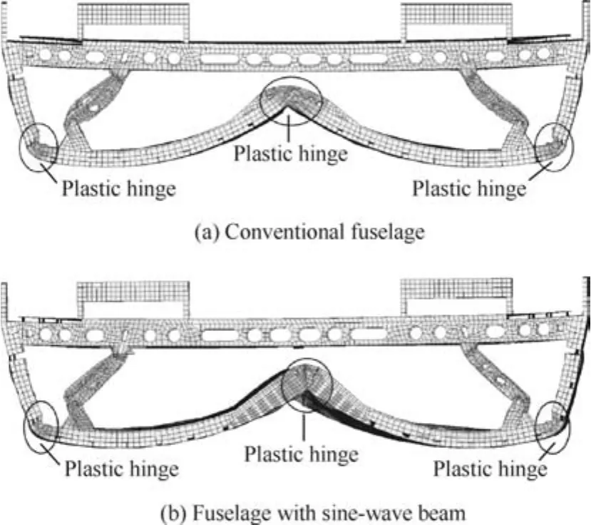
Fig.6 Failure behavior of conventional fuselage and fuselage with sine-wave beam.
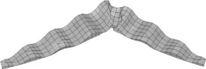
Fig.7 Failure behavior of sine-wave beam.
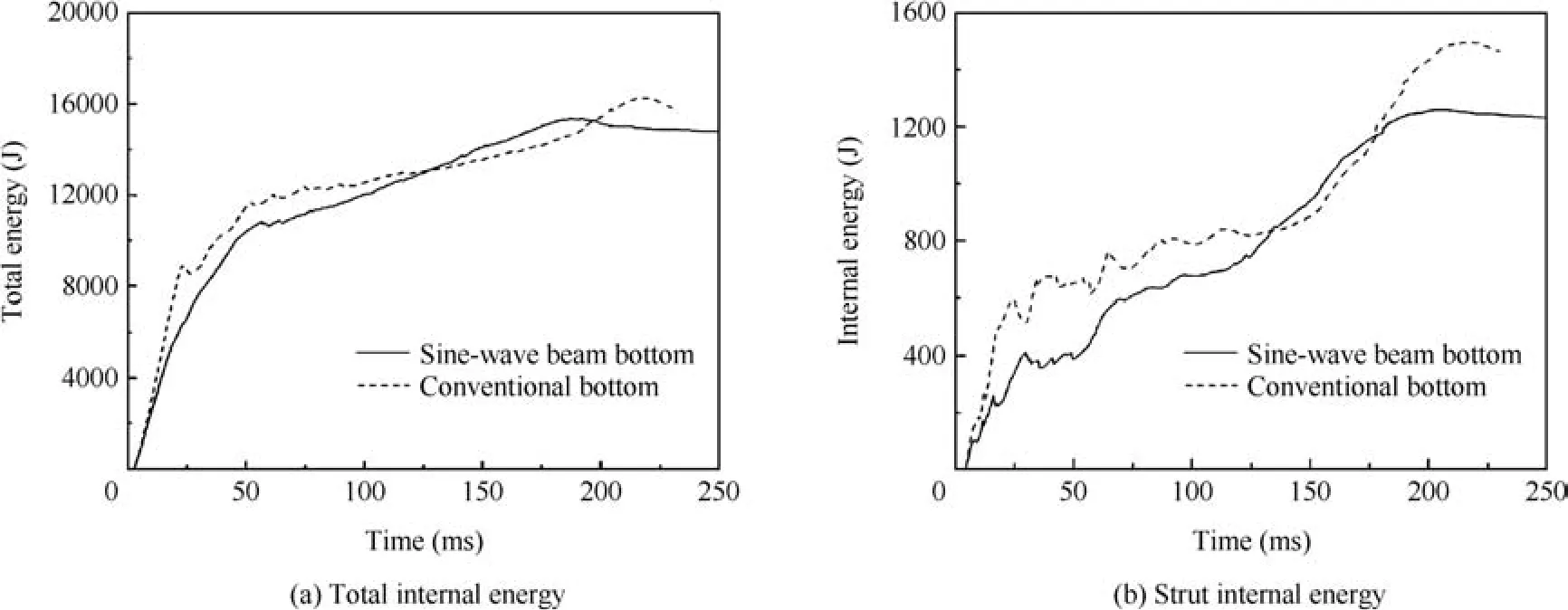
Fig.8 Total internal energy and strut internal energy of two fuselages.
The acceleration,velocity and displacement curves of two fuselages are exhibited in Fig.9.The fuselage with sine-wave beam has better acceleration characteristics for the lower impact load and more stable impact load.The initial peak acceleration is 17.73gfor conventional fuselage,while that of proposed fuselage is just 16.10g.The latter is 9.2%lower than the former.As shown in Fig.9(a),two high peak accelerations are demonstrated in the acceleration curve of conventional fuselage,while the number of high impact load of proposed fuselage is much less than that of the conventional fuselage.In addition,there is a peak acceleration around 220 ms due to the collision between cargo floor and cabin floor for the conventional fuselage,and this maximum acceleration reaches above 15gfor the residual impact kinetic energy.Better than the conventional type,there is no secondary impact load for the proposed fuselage because of the sine-wave beam bottom structure.The impact velocity curve could be given by the integral of acceleration curve,and it is corresponding with the acceleration curves,as shown in Fig.9(b).The velocity increasing rate of conventional fuselage is larger than that of proposed fuselage for the high impact load in the beginning.The impact velocities of two fuselages reach 0 m/s at the same time although the two impact history curves are greatly different.As shown in Fig.9(c),the displacement of conventional fuselage is smaller than that of proposed fuselage for the low impact load in the beginning,but its final displacement is a little larger.
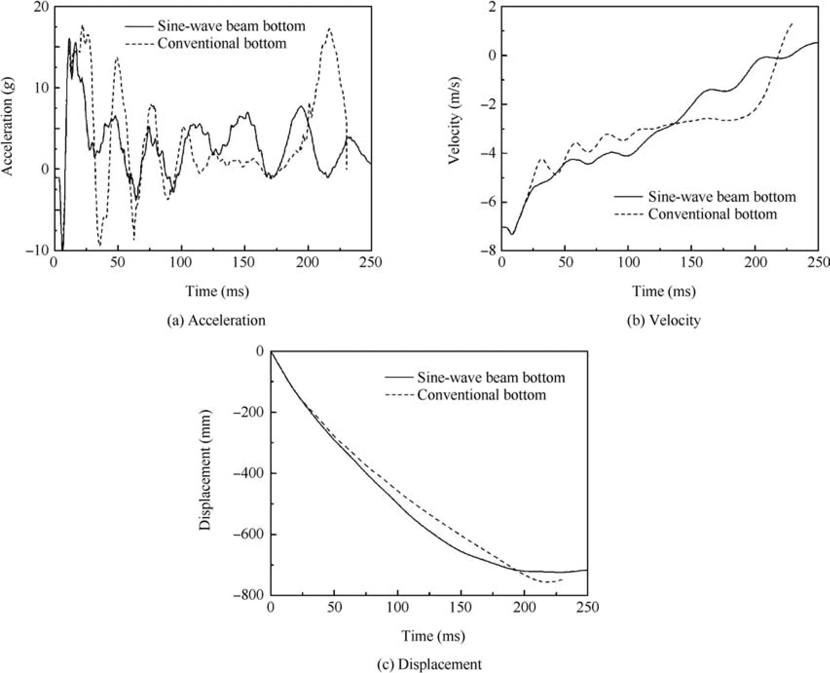
Fig.9 Acceleration,velocity and displacement of two fuselages.
4.Integrated design of sine-wave beam and different struts
The aircraft with the sine-wave beam has better crashworthiness performance than that of the conventional type from the previous analysis.Besides,other components including frame and strut have great influence on the crashworthiness performance of aircraft.Although the frame determining the entire crashworthiness performance absorbs nearly more than half of impact kinetic energy,its energy absorption ability is affected by the strut.To better demonstrate the crashworthiness performance of aircraft,three different strut design concepts including the single shell with holes,single shell and square tube are integrated with the sine-wave bottom structure here.
4.1.Failure behavior
The failure behavior of the fuselage with single shell and square tube is exhibited in Fig.10.The fuselages with and without hole in single shell strut have the same location and number of plastic hinges exhibited in Figs.6(b)and 10(a).The fuselages with strut have three plastic hinges which is consistent with the fuselage without strut.Removing the hole in strut would reinforce its rigidity and intensity,thus the deformation of single shell is smaller than single shell with holes.The bottom frame between the two symmetrical struts is forced to deform,and the plastic deformation of bottom structure increases for the enhancement of strut rigidity.In addition,the fuselage tilts along the longitudinal direction for the asymmetry of strut.However,the location of plastic hinges is close for the above two cases.Different from the two cases,the square tube strut totally alters the location of plastic hinges,and frame damage just locates between two struts.The frame under the strut suffers large plastic deformation.The failure behavior of three different kinds of struts is demonstrated in Fig.11.The deformation of strut increases with the decreasing of its rigidity.The rigidity of single shell with hole is so small,and it plays relatively small role during impact accident.However,the deformation of the entire fuselage is altered for the increasing of rigidity by removing the hole from strut.For the square tube,it keeps integrity during impact process,and it forces the location alteration of plastic hinges.

Fig.10 Failure behavior of fuselage with single shell and fuselage with square tube.
4.2.Energy absorption ability
The total internal energy curves of three different fuselages are exhibited in Fig.12.The internal energy curves of three fuselages in the beginning 50 ms are nearly the same because the deformation of this phase is focused on the bottom area.There is a great difference of final internal energy among three fuselages for their rebound energy and vibration energy.It could be seen that the fuselage with square tube has the largest rebound velocity for the increasing of fuselage rigidity.The fuselage with single shell has the optimal internal energy curve.The impact process is stable because the internal energy curve is smoother than those of two other fuselages.The internal energy curves of the sine-wave beam are exhibited in Fig.13.The bending deformation is the failure behavior of different sine-wave beams,thus the three internal energy history curves are consistent in the beginning 100 ms.The largest and smallest internal energy of sine-wave beam is the single shell with holes and square tube,respectively.The energy absorption ability of strut is exhibited in Fig.14.The final internal energy of single shell is about two times that of single shell with holes,and four times that of square tube.It is concluded that the fuselage having single shell without holes is better than that having single shell with holes and square tube as the strut structure from the viewpoint of energy absorption ability.

Fig.11 Failure behavior of different struts.
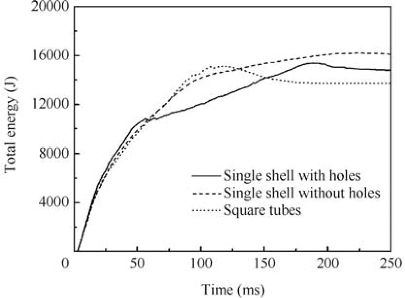
Fig.12 Total internal energy of fuselage with different struts.

Fig.13 Internal energy of sine-wave beams.

Fig.14 Internal energy of struts.
4.3.Acceleration characteristics
Controlling the acceleration characteristics under the living limit of human being is the key crashworthy design objective of fuselage.The acceleration characteristics including the initial peak acceleration and history curve should be given great attention.The initial peak accelerations and its history curve could be seen in Fig.15(a).The initial peak accelerations are 16.10g,20.31gand 20.71gfor fuselage with three kinds of struts,i.e.the single shell with holes,single shell without holes and square tubes,which is an increasing function with respect to the strut stiffness.The second and third peak accelerations for square tube are larger than that of single shell with or without holes,but its acceleration is converged to zero after 120 ms.Different from square tube,although the initial peak acceleration is relatively small,there are several peak accelerations above 5gin the entire impact process of single shell with holes because of the residual impact kinetic energy,and it is caused by the small strut stiffness and the limited energy absorption ability.The acceleration characteristics of single shell have the distinct advantages compared with other two cases.The second peak acceleration for single shell without holes is very small,and the following acceleration curve also keeps under a low level.This is the perfect acceleration history curve for the low peak acceleration and its rapid convergence rate.In conclusion,the acceleration characteristic of fuselage with single shell is better than that of fuselage with single shell with holes or square tube for its low initial peak acceleration and better acceleration history curve.The velocity and displacement history curves are exhibited in Figs.15(b)and(c).It could be seen that fuselage with square tube reaches 0 m/s at about 120 ms,while the other two are about 250 ms.In addition,it has the largest rebound velocity,and the maximum is nearly 2 m/s.The maximum displacements for square tube,single shell without and with holes are 450,600 and 700 mm,respectively,and it is an increasing function with respect to strut rigidity.
It could be concluded that both of sine-wave beam and strut stiffness have great influence on the crashworthiness of fuselage.The strut not only dissipates much more portion of impact kinetic energy but also improves the energy absorption of fuselage.The crashworthiness performance of fuselage with single shell is better than that of fuselage with single shell with holes or square tube for the reasonable impact load history curve,better failure behavior and energy absorption ability.To obtain better crashworthy fuselage,the sine-wave beam and strut should be integrated and designed.

Fig.15 Acceleration,velocity and displacement of different fuselages.
5.Conclusions
(1)The lifting of bottom frame is the effective approach to provide the crushing platform for energy absorption structure.The sine-wave bottom structure under the frame could not only dissipate much proportion of impact kinetic energy but also reduce the initial peak acceleration.
(2)The single shell without holes could improve not only the failure behavior but also the acceleration characteristics compared with single shell with holes and square tube.The fuselage with moderate stiffness strut and sine-wave beam bottom structure has the optimal crashworthiness performance.Both of bottom structure and strut should be integrated and designed for the crashworthy aircraft fuselage requirement.
Acknowledgement
The authors thank the anonymous reviewers for their critical and constructive review of the manuscript.This study was co-supported by the National Natural Science Foundation of China(No.11402011)and the Fundamental Research Funds for the Central Universities.
1.Guo BD,Liu PQ,Qu QL,Wang JQ.Effect of pitch angle on initial stage of a transport airplane ditching.Chin J Aeronaut2013;26(1):17–26.
2.Ren YR,Xiang JW.Crashworthiness uncertainty analysis of typical civil aircraft based on box-Behnken method.Chin J Aeronaut2014;27(3):550–7.
3.Sturm R,Hepperle M.Crashworthiness and ditching behavior of blended-wing-body(BWB)aircraft design.Int J Crashworthiness2015;20(6):592–601.
4.Adams A,Lankarani HM.A modern aerospace modelling approach for evaluation of aircraft fuselage crashworthiness.Int J Crashworthiness2003;8(4):401–13.
5.Adams A,Thorbole CK,Lankarani HM.Scale modelling of aircraft fuselage:an innovative approach to evaluate and improve crashworthiness.Int J Crashworthiness2010;15(1):71–82.
6.Crankhite JD,Berry VL.Crashworthy airframe design concepts:fabrication and testing.Fort Worth(TX):Bell Helicopter Textron,Inc.;1982.Report No.:NASA-CR-3603.
7.Ren YR,Xiang JW.Energy absorption structures design of civil aircraftto improve crashworthiness.AeronautJ2014;118(1202):383–98.
8.Meng FX,Zhou Q,Yang JL.Improvement of crashworthiness behavior for simplified structural models of aircraft fuselage.Int J Crashworthiness2011;14(1):1–15.
9.Zheng JQ,Xiang JW,Luo ZP,Ren YR.Crashworthiness design of transport aircraft subfloor using polymer foams.Int J Crashworthiness2011;16(4):375–83.
10.Paolo F,Bonnie W,Francesco D,Mostafa R,Mark H,Alan B.LS-DYNA MAT54 modeling of the axial crushing of a composite tape sinusoidal specimen.Compos Part A Appl Sci Manuf2011;42(11):1809–25.
11.Jose Luis San V,Francisco B,Francisco M.Simulation of impact on composite fuselage structures.European congress on computational methods in applied sciences and engineering ECCOMAS 2000;2000 Sep 11–14;Barcelona,Spain;Regensburg,Germany:ECCOMAS;2000.
12.Wiggenraad JFM,Michielsen ALPJ,Santoro D,Lepage F,KindervaterC,Beltran F.Developmentofacrashworthy composite fuselage structure for a commuter aircraft.American Helicopter Society 57th annual forum;2001 May 9–11;Washington,D.C.;Virginia,USA:AHS;2001.
13.David D,Didier J,Michel M,Gerard W.Evaluation of finite element modeling methodologies for the design of crashworthy composite commercial aircraft fuselage.24th international congress of the aeronautical sciences.Yokohama,Japan;Stockhom,Sweden:ICAS;2004.
14.Huey DC,Sotiris K.Energy absorbing beam design for composite aircraft subfloor.34th AIAA/ASME/ASCE/ASC structures,structuraldynamics,andmaterialsconference.La Jolla,CA;Reston:AIAA;1993.
15.Zheng JQ,Xiang JW,Luo ZP,Ren YR.Crashworthiness layout of civil aircraft using waved-plate for energy absorption.Acta Aeronaut Astronaut Sin2010;31(7):1376–402 Chinese.
16.Zou TC,Mou HL,Feng ZY.Research on effects of oblique struts on crashworthiness of composite fuselage sections.J Aircr2012;49(6):2059–63.
17.Ren YR,Xiang JW.The crashworthiness of civil aircraft using different quadrangular tubes as cabin-floor struts.Int J Crashworthiness2011;16(3):253–62.
18.Ren YR,Xiang JW.A comparative of the crashworthiness of civil aircraft with different strut configurations.Int J Crashworthiness2010;15(3):321–30.
19.Heimbs S,Strobl F,Middendorf P.Integration of a composite crash absorber in aircraft fuselage vertical struts.Int J Vehicle Str Syst2011;3(2):87–95.
20.Liu XC,Sun XS.Drop test and crash simulation of a civil airplane fuselage section.Chin J Aeronaut2015;28(2):447–56.
21.Liu XC,Zhou SF,Ma JF,Sun XS,Mu RK.Correlation study of crash analysis and test of civil airplane sub-cabin energy absorption structure.Acta Aeronaut Astronaut Sin2012;33(12):2202–10 Chinese.
13 May 2015;revised 20 October 2015;accepted 8 January 2016
Available online 24 February 2016
ⓒ2016 Chinese Society of Aeronautics and Astronautics.Published by Elsevier Ltd.This is an open access article under the CC BY-NC-ND license(http://creativecommons.org/licenses/by-nc-nd/4.0/).
*Corresponding author.
E-mail addresses:renyiru@hnu.edu.cn(Y.Ren),xiangjw@buaa.edu.cn(J.Xiang),zhengjianqiang@comac.cc(J.Zheng),luozp@buaa.edu.cn(Z.Luo).
Peer review under responsibility of Editorial Committee of CJA.
Ren Yiruis an assistant professor and master supervisor at College of Mechanical and Vehicle Engineering,Hunan University.He received the B.E.and Ph.D.degrees from Harbin Engineering University and Beihang University in 2006 and 2011,respectively.His main research interests are aircraft design,mechanics of composite material,crashworthiness design,and structural dynamics.
Xiang Jinwuis a full professor and Ph.D.supervisor at School of Aeronautic Science and Engineering,Beihang University.His area of research includes aircraft design,structural dynamics and aeroelasticity.
Zheng Jianqiangis an engineer at Beijing Aeronautical Science and Technology Research Institute of COMAC.He received the Ph.D.degree from Beihang University in 2012.His main research interests are aircraft design and structural dynamics.
Luo Zhangpingis an associate professor and master supervisor at School of Aeronautic science and Engineering,Beihang University.His area of research includes aircraft design and structural dynamics.
杂志排行
CHINESE JOURNAL OF AERONAUTICS的其它文章
- Hypersonic starting flow at high angle of attack
- Advances and trends in plastic forming technologies for welded tubes
- Instability and sensitivity analysis of flows using OpenFOAM®
- Numerical simulations of high enthalpy flows around entry bodies
- Modeling and simulation of a time-varying inertia aircraft in aerial refueling
- Experimental investigations for parametric effects of dual synthetic jets on delaying stall of a thick airfoil