Containment ability and groove depth design of U type protection ring
2016-11-23BiCongerXunHijunHungXinninHeZeknHongWeirong
Bi Conger,Xun Hijun,*,Hung Xinnin,He Zekn,Hong Weirong
aHigh-speed Rotating Machinery Laboratory,Institute of Chemical Machinery,Department of Chemical Engineering,Zhejiang University,Hangzhou 310027,China
bCollaborative Innovation Center for Advanced Aero-engine,Beijing 100083,China
Containment ability and groove depth design of U type protection ring
Bai Congera,b,Xuan Haijuna,b,*,Huang Xianniana,b,He Zekana,b,Hong Weironga
aHigh-speed Rotating Machinery Laboratory,Institute of Chemical Machinery,Department of Chemical Engineering,Zhejiang University,Hangzhou 310027,China
bCollaborative Innovation Center for Advanced Aero-engine,Beijing 100083,China
Disk fragments containment;High energy rotor;Numerical analysis;Protection ring;Verification test
High-energy rotor uncontained failure can cause catastrophic damage effects to aircraft systems if not addressed in design.In this paper,numerical simulations of three high-energy rotor disk fragments impacting on U type protection rings are carried out using LS-DYNA.Protection rings with the same mass and different groove depths are designed to study the influence of the groove depth.Simulation results including kinetic energy and impact force variation of single fragment are presented.It shows that the groove depth infects both the axial containment ability of the protection ring and the transfer process of energy.The depth of groove ought to be controlled to an appropriate value to meet both the requirement of axial containment and higher safety factor.Verification test on high-speed spin tester has been conducted and shows that protection ring with appropriate U structure can resist the impact of the disk burst fragments.The ring is inflated from a circular to an oval-triangle shape.The corresponding simulation shows good agreement with the test.
1.Introduction
In turbine cooler of environment control system(ECS),auxiliary power unit(APU)and air turbine starter in aircraft,failed high speed rotor can be released as high-energy fragments,affecting flying performance in a number of direct and indirect ways and even leading to the loss of airplane.1With a more stringent working condition of higher temperature and rotational velocity,degradation and burst failure are more likely to occur,especially on the critical disks.Even though disk burst accidents happen infrequently nowadays,they are not completely avoidable.2Due to the catastrophic results,specific provisions are established for containment ability in both civil and military airplane specifications.Federal Aviation Administration(FAA)Federal Aviation Regulations(FARs)set requirements for equipment containing high-energy rotors oftransport category airplane in Part 25.3Corresponding technical standards for APU are also put forward in TSO-C77b,gas turbine auxiliary power units by FAA.4
An available practice for studying the containing process is the combination of experimental tests and numerical simulations.With the advent of computer non-linear finite element codes,numerical simulations have become an important means for researchers to conduct their studies.A number of investigations have included experiments and numerical simulations of high-energy disk fragments containment.Hagg and Sankey5carried out tests which showed that containment of missile-like disk quarter fragments by a steel cylindrical shell is a continuous two-stage process.In Stage 1,the main objects to be considered are the loss in kinetic energy of system and the energy dissipated in plastic compression and shear strain.For non-perforation,the process enters Stage 2,which mainly involves dissipation of energy in plastic tension strain.The effects of mesh refinement on numerical simulations of uncontained engine debris impact on thin plates were studied by Norman Jr.6and Ambur7et al.In their studies,it was concluded that very fine mesh should be used to predict damage similar to that obtained from experimental results.Eric and Steven8proposed a simulation method of using ANSYS/LSDYNA to develop an analysis method that could provide more accurate predictions of containment failure limits for a wider range of disk and containment geometries.Li et al.9carried out aeroengine turbine blade and disk containment tests respectively and analyzed them using numerical simulations with ANSYS/LS-DYNA.He et al.10conducted numerical study of an aeroengine fan blade/casing impact process and the effects of stress initialization on simulation are assessed.Liu et al.11studied compressor disk containment of aircraft cooling turbine used in aircraft environment control system.The disk burst into 3 pieces and containment process was investigated in combination of experimental results and numerical results.In this paper,numerical models are established first to predict the containment ability and loads.Then,simulation results are validated through test data.Detailed data obtained from numerical results are used to analyze the variation of the energy,the force,etc.
For protection rings,U structure seems to be an optimal design for disk bursting containment of high-energy rotor.In order to meet the requirement of containment,the protection rings must have enough thickness and U groove depth to resist the high-energy fragments.But excessive thickness results in excessive weight.To achieve a minimum weight of the casing which can offer enough containment strength,reasonable structural designs for the casing are expected.In this paper,containment ability and groove depth design of U type protection ring are studied.
This paper consists of five sections.Following this introduction,numerical simulations of fan impeller fragments in air turbine cooler impacting on the U type protection rings appears in Section 2.The containment ability of rings with different U-groove depths is studied using ANSYS/LS-DYNA.Section 3 shows a verification containment test on highspeed spin tester with the optimal protection ring chosen from the simulations.Section 4 describes the simulation of containment process under the test condition.Comparisons between the test and the simulation results are discussed.The last section presents the conclusions.
2.Containment ability of different U geometries
With the aim of saving costs and improving efficiency of research,a series of numerical simulations is carried out to study the effect of U geometry to the containment ability using ANSYS/LS-DYNA.
2.1.Design objective
Containment ability is studied through the simulation of fan impeller disk fragments in air turbine cooler impacting on the protection casing.In practical situation,fan protection casing consists of three components,among which the pipe and the protection ring play a major role of protection.Thus,the model in simulation is built without the outer shell(see Fig.1).The installation position of the protection ring is designed(see Fig.2).
Referring to SAE Aerospae-ARP-85F12,the containment speed is defined 125%of the maximum speed resulting from normal operating condition.According to the design parameter of the air turbine cooler,the fan disk is supposed to burst with the speed of 70,069 r/min.The main design parameters are listed in Table 1.It should be noted that 2Cr13,the material of the protection ring,is a common material used in aerospace for its good corrosion resistance to the atmosphere.Available material parameters for simulation and fine machinability lead the choice.
2.2.Failure mode
According to FARs,it must be shown by test that high-energy rotor equipment can contain any failure of a high energy rotor that occurs at the highest speed obtainable with the normal speed control devices inoperative.TSO-C77b also puts forward provision that containment must be substantiated in accordance with the condition of hub containment in APU.4In advisory circular(AC)20-128A of FAA,engine and APU failure model include single one-third disc fragment,intermediate fragment,fan blade fragment,etc.13Before the test,the most dangerous bursting mode must be determined.In order to simplify the question,the impeller is assumed to be a disk with a radius ofr.Therefore,the rotational kinetic energy(Ec)of the disk can be calculated as

wheremis the total mass of the impeller and ω the disk rotating/burst speed.
During the process of impacting,translational kinetic energy(Et)plays a leading role among all the types of the energy of fragment.Assume the disk bursts intonequal parts.Thus,the centroid radius(rm)andEtof a fragment can be defined as

The ratio ofEttoEcis presented as


Fig.1 Geometric model of test components.
Fig.3 shows a drawing of energy ratio according to Eq.(4).It is possible to conclude that for a certain disk,the maximum translational kinetic energy of a single fragment occurs when the disk bursts into three parts.
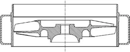
Fig.2 Schematic of fan components.

Table 1 Main design parameters of components.

Fig.3 Ratio of translational kinetic energy(Et)of the fragment to kinetic energy of the disk(Ec).
2.3.Different U protection rings
Five protection rings with the same mass are studied in the simulation.The heights of rings are certain because of the overall structure.Fig.4(a)presents four ring structures of different U-groove depths,among which Type I has the deepest U-groove of 17 mm,half height of the ring.U-groove depth is successively and uniformly decreased from Type I to Type IV.A straight cylinder is used in Type V for comparison with U geometries(see Fig.4(b)).To obtain a more obvious contrast,thickness of Type II is set to approach a critical state.
It should be noted that the five rings are controlled to be of the same mass of 0.57 kg.The corresponding wall thicknesses are designed using UG,listed in Table 2.
2.4.Finite element model
To improve simulation efficiency,geometric characteristics that make few effects of containment are simplified.Finite element models are shown in Fig.5.To capture the detailed behavior of the case,at least three elements through the thickness of the case are set.All elements are set to be 8-node solid element which can observe the failure mode through the thickness while other element types such as the shell element cannot easily obtain the message.14
Material model is a key factor affecting the accuracy of results from a nonlinear finite element simulation.In this paper,the Johnson–Cook(JC)model is chosen for the reason shown in Refs.9,15and has already been described def initely.16,17The material parameters used in this paper are listed in Table 3 and taken from Refs.18–20.In Table 3,Ais the yield stress,Bandnrepresent the effects of strain hardening,Cis the strain rate constant andmrepresents the temperature constant in constitutive model.16For fracture model,D1,D2,D3,D4,D5are failure constants determined by material tests.17

Fig.4 Five cross-sections of protection ring.

Table 2 Geometries of five protection rings.
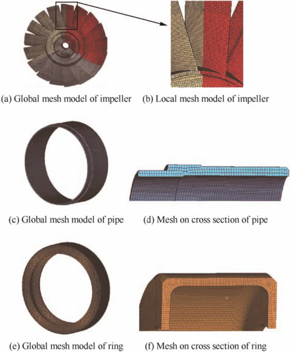
Fig.5 Finite element models.
The elements of impeller fragments are given an initial angular velocity.Surface to surface contact between the disk fragment and the containment structure is modeled using a kinematic contact algorithm.The contact stiffness scale factor is defined as 1.0 and the friction coefficient is defined as typical values of 0.15.9
2.5.Comparison and analysis
Fig.6 shows the simulation results of different protection rings.It can be observed that Type I protection ring is torn by one fragment and a piece of breach appears.Fragments are contained within Type II.Since the outside surface of the ring damaged slightly,it can be defined as a critical state.For Types III–V,damage of the rings does not occur,but the fragments fly out in axial direction.
It is shown that smaller depth of the groove leads to less obvious deformation of the protection ring.However,the fragments are more likely to run out of the covered range of ring and fragments flying along axial-direction may cause damage to other components.High energy disk fragments containment should be defined to capture the fragments within the ring,so Type II protection ring,which successfully contains the fragments in both radial and axial direction,shows greater fitness.
From the forgoing it follows that U structure performs better than straight cylinder in containing the fragments.Under the condition of a constant mass of ring,greater depth of the groove leads to smaller thickness of the impacting zone,which indicates the reduction of safety factor of the protection ring.As shown in Fig.6(a),ring penetration happens.When designing protection rings,the depth of groove ought to be controlled to an appropriate value.
The above analysis shows that U-groove depth plays an essential role for containment.In addition,it has influence on other aspects.On the one hand,the protection ring requires sufficient stiffness which is directly related to the groove depth.On the other hand,U-groove depth has an effect on the energy transfer process between the fragment and ring.Fig.7 and Table 4 show the kinetic energy variation of the fragments.With the groove depth decreasing,the residual kinetic energy(after impacting)of the fragments increases slightly.Axial deviation of fragments emerges due to the interaction of themselves,for they rebound from the casing with certain kinetic energy.It is shown that the impacting force of the fragments tends to have a lower maximum value and a longer duration with a deeper U-groove,as Fig.8 presents.The maximum impact force is also carried backward as the groove depth increases.

Fig.6 Simulation results of different protection rings.

Table 3 J-C constitutive relation and fracture criterion constant of TC4,2A12 and 2Cr13.
It is possible to conclude that appropriate U-groove depth helps to buffer the impact of fragments,leading to an adequate interaction and energy transfer.Rebounding fragments with less kinetic energy and the obstruction of U-groove are conducive to axial containment.However,considering the requirement of less weight and volume,it is also unsuitable for an excessive depth.The present results serve to illustrate that Type II protection ring,with a more suitable U-groove depth,can meet both the requirement of axial containment and higher safety factor.
3.Verification test and results
Component level containment test using high-speed spin tester is an appropriate method to study the behavior of fragments/casing impact,penetration and perforation.21Containment ability studied above was verified through a test.Since tests are relatively expensive,they were carried out only for once.
3.1.Test arrangement
Protection case used in the test includes a U type protection ring,a pipe and the outer shell.According to the analysis in Section 2,Type II protection ring,with a relatively suitable U-groove depth of 13 mm,was chosen to be tested.Considering the expected result of containment and the limited cost,thickness is redesigned to 2.3 mm,with a safety factor of 1.1.
The test was conducted on the ZUST1 rotor high-speed spin tester in High-Speed Rotating Machinery Laboratory in Zhejiang University.Parameters of this spin facility are presented in Ref.21.For the requirement of a fan disk burst in speed ranging from 70069 to(75069±50)r/min,a speed increasing gear box with ratio of 4.07 is added to attain a secondary acceleration with a final output maximum speed up to 96000 r/min.The experiment was conducted at room temperature.Fig.9 presents the sketch of the testing rig and pretest photo in testing chamber.

Fig.7 Kinetic energy variation of single fragment.

Table 4 Residual kinetic energy of single fragment.
3.2.Impeller bursting method
Before test,the fan impeller is supposed to be notched along radial direction at three symmetrical positions circumferentially with the aim of bursting into 3 pieces at target speed range along the direction of presented crack(see Fig.10).In Fig.10(a),area without the section line is supposed to be cut,thus,rcrepresents the distance from center to terminal of the crack andLis the remaining length along the crackdirection.Fracture occurs in the notched cross-section at which the localized plastic zone expands with the increase of rotating speed.When the circumferential stress at the crosssection is beyond the ultimate tensile strength of the material,the impeller bursts with a certain kinetic energy.The average stress method is used to calculate the notched cross-section circumferential stress roughly and provides guidance for cutting.In order to be workable,the process of notching is supposed to be conducted in multiple steps.
3.3.Results and analysis
Conservatively,the initial remaining length of the impeller(L)was 9.5 mm and impeller burst did not occur at the highest speed,75069 r/min.The same procedure was carried out until the remaining length reduced to 7.0 mm,with the burst speed of 75069 r/min which is in accordance with simulations.
The first testing site is presented in Fig.11.It is shown that the casing can resist the impact of three high-energy disk fragments.Blades at three impacting points wore seriously and missed;the pipe was penetrated and the disk fragments were successfully contained within the protection ring.The U type protection ring deformed from a circular to an oval-triangle shape.The test result indicates that the analysis of U type protection ring is conductive.
4.Numerical simulation of test
Since the actual bursting speed is 5000 r/min more than that in the simulation before,numerical simulation of the test is conducted with the aim of further verification and better understanding of the impact process.
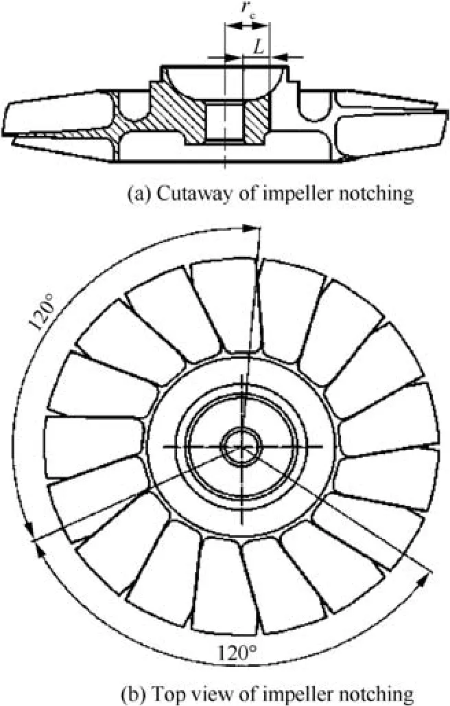
Fig.10 Impeller notching pattern.

Fig.11 The first testing site.
Geometric configurations of the disk and the protection ring are the same as those used in the test.Simulation method follows that in Section 2.
Simulation results indicate that the main failure modes of blades include crispation,wear of main impact zone and fracture of the root.It is found that the fragments breach the pipe and cause dishing deformation on the ring.Bulge deformation occurs at the impact region of the protection ring,and because of the three impact points from the disks’fragments,the ring deformed from a circular to an oval-triangle shape.
The combined disk fragments of simulation show good agreement with the test.Comparison is shown in Fig.12.Fig.13(a)presents the whole containment components in the test.Pipe and protection ring in Figs.13(b)and(c)also accurately reveal the failure characteristics.According to the high concordance between the simulation and the test in Section 3,the simulation method can be regarded reliable.
Fig.14 shows the von Mises stress contour plots at 8 different time points.The fragments are released after they separate from each other.The blade tip firstly impacts the pipe and bends due to extrusion,and an impact force peak occurs at 0.06 ms(see Fig.15).As a result,for each disk fragment,blades on one side are subjected to severe extrusion while slight impacts occur on the other side.The pipe is perforated firstly at the time of 0.21 ms,meanwhile the impact force reaches the maximum.Contact of the protection ring and the fragments occurs at 0.30 ms,at this point,the pipe is severely deformed and damaged.Hereafter,a part of the fragment proceeds to tear the pipe,and other part impacts the ring.The third impact force peak in Fig.15 at time 0.39 ms is the result from the impact of the fragment and the protection ring.After the time of 3 ms,most of the initial kinetic energy of the fragments is consumed.

Fig.12 Comparison between test and simulation of impeller.
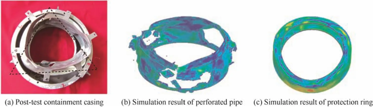
Fig.13 Comparison between test and simulation of casing.
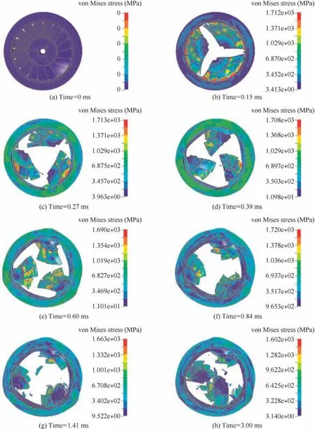
Fig.14 Containment simulation results.

Fig.15 Impact force progress.
5.Conclusions
In this paper,numerical simulations of high-energy rotor disk fragments impacting on different U-type protection ring are carried out using LS-DYNA.Verification test and the correspondingsimulation werealso performed.Comparisons between the experimental and the numerical results show that the numerical simulations are in fitness.Based on the simulation observations and test results presented,the following conclusions were drawn:
(1)While containing fragment of 1/3 disk,the U structure performs better than straight cylinder in protection ring design.U-groove depth infects both the axial containment ability and the energy transfer process between fragments and rings.The depth of groove ought to be controlled to an appropriate value to meet both the requirement of axial containment and higher safety factor.
(2)Containment test shows that the fragments perforate the pipe and cause inflation of the U type protection ring.The ring is inflated from a circular to an oval-triangle shape.The test result indicates that the numerical analysis of U type protection ring is conductive.Simulation shows good agreement with the test and the method can be regarded as reliable.
1.Mousa NA,Whale MD,Groszmann DE,Zhang XJ.The potential for fuel tank fire and hydrodynamic ram from uncontained aircraft engine debris.Washington,D.C.:US Department of Transportation,Federal Aviation Administration;1997(Report No.:DC 20591 DOT/FAA/AR-96/95).
2.Xuan HJ,Liu LL,Feng YM,He Q,Li JJ.Containment of highspeed rotating disk fragments.J Zhejiang Univ Sci A2012;13(9):665–73.
3.FAA Federal Aviation Regulations.Airworthiness standards:Transport category airplanes.Washington,D.C.:Federal Aviation Administration;1984(FAA-FAR-25).
4.Department of Transportation,Federal Aviation Administration.Gas turbine auxiliary power units.Washington,D.C.:US Department of Transportation,Federal Aviation Administration;2000.p.16–7(Technical Standard Order(TSO-C77b)).
5.Hagg AC,Sankey GO.The containment of disk burst fragments by cylindrical shells.J Eng Power1974;96(2):114–23.
6.Norman Jr FK,Jaunky N,Lawson RE,Ambur DR.Penetration simulation for uncontained engine debris impact on fuselage like panels using LS-DYNA.Finite Elem Anal Des2000;36(2):99–133.
7.Ambur DR,Jaunky N,Lawson RE.Numerical simulations for high-energy impact of thin plates.Int J Impact Eng2001;25(7):683–702.
8.Eric S,Steven H.The use of LS-DYNA models to predict containment of disk burst fragments.10th international LS-DYNA user conference.2008 Jan 1–9;Detroit(MI).
9.Li JJ,Xuan HJ,Liao LF,Hong WR,Wu RR.Penetration of disk fragments following impact on thin plate.J Zhejiang Univ Sci A2009;10(5):677–84.
10.He Q,Xuan HJ,Liu LL,Hong WR,Wu RR.Perforation of aeroengine fan casing by a single rotating blade.J Aerosp Sci Technol2013;35(1):234–41.
11.Liu LL,Xuan HJ,Zhang N,Hong WR.Research on compressor disc containment of a cooling turbine.22nd proceedings of the conference on structural engineering.2013 Aug 9–11;Urumqi,China.Beijing:Engineering Mechanics Press;2013.p.190–5[Chinese].
12.SAE Aerospace.SAEAerospace-ARP-85F.Airconditioning systems for subsonic airplanes.Warrendale(PA):Society of Automotive Engineers(SAE)Aerospace;2012.p.27.
13.Federal Aviation Administration.Design considerations for minimizing hazards caused by uncontained turbine engine and auxiliary power unit rotor failure.Washington,D.C.:Federal Aviation Administration;1997(Report No.:FAA Advisory Circular No.20-128A).
14.He Q,Xuan HJ,Liao LF,Hong WR,Wu RR.Simulation methodology development for rotating blade containment analysis.J Zhejiang Univ Sci A2012;13(4):239–59.
15.Teng X,Wierzbicki T.Evaluation of six fracture models in high velocity perforation.Eng Fract Mech2006;73(12):1653–78.
16.Johnson GR,Cook WH.A constitutive model and data for metals subjected to large strains,high rates and high temperatures.Proceedings of the 7th international symposium on ballistics;1983 Apr 19–21;Hague,Netherlands.p.541–57.
17.Johnson GR,Cook WH.Fracture characteristics of three metals subjected to various strains,strain rates,temperatures and pressures.Eng Fract Mech1985;21(1):31–48.
18.Li J,Xie LJ,Wang XB,Wang L,Xie J,Yang HJ.Material constitutive model of 2Cr13 for FEA of chip formation process.Appl Mech Mater2008;10(12):796–800.
19.Chen G,Chen ZF,Tao JL,Niu W,He P.Dynamic mechanical property research of TC4.J Exp Mech2005;20(4):605–9[Chinese].
20.Murat B,Steve K,Matti JL.Explicit finite-element analysis of 2024-T3/T351 aluminum material under impact loading for airplane engine containment and fragment shielding.J Aerosp Eng2009;22(3):287–95.
21.Xuan HJ,Wu RR.Aeroengine turbine blade containment tests using high-speed rotor spin testing facility.Aerosp Sci Technol2006;10(6):501–8.
21 August 2015;revised 27 November 2015;accepted 31 December 2015
Available online 23 February 2016
ⓒ2016 Chinese Society of Aeronautics and Astronautics.Published by Elsevier Ltd.This is an open access article under the CC BY-NC-ND license(http://creativecommons.org/licenses/by-nc-nd/4.0/).
*Corresponding author.Tel.:+86 571 87951223.
E-mail addresses:baiconger@zju.edu.cn(C.Bai),marine@zju.edu.cn(H.Xuan).
Peer review under responsibility of Editorial Committee of CJA.
BAI Congeris a Ph.D.candidate at Institute of Process Equipment in Zhejiang University.Her research interests are structure and strength of aeroengine,especially of containment design methodology study for high-energy rotor disk fragments.
XUAN Haijunis an associate professor and Ph.D.supervisor at Highspeed Rotating Machinery Lab.,Zhejiang University,Hangzhou,P.R.China.He received the Ph.D.degree from the same university in 2004.His current research interests are rotordynamics,rotor strengthen,disk low cycle fatigue,rotating blade high cycle fatigue and impacted structure dynamics response in high-speed rotating machinery.
杂志排行
CHINESE JOURNAL OF AERONAUTICS的其它文章
- Hypersonic starting flow at high angle of attack
- Advances and trends in plastic forming technologies for welded tubes
- Instability and sensitivity analysis of flows using OpenFOAM®
- Numerical simulations of high enthalpy flows around entry bodies
- Modeling and simulation of a time-varying inertia aircraft in aerial refueling
- Experimental investigations for parametric effects of dual synthetic jets on delaying stall of a thick airfoil