Precessing motion in stratified radial swirl flow
2016-11-23QinHoLinYuzhenLiJio
Qin Ho,Lin Yuzhen,*,Li Jio
aNational Key Laboratory of Science and Technology on Aero-Engine Aero-thermodynamics,School of Energy and Power Engineering,Beihang University,Beijing 100083,China
bAVIC Commercial Aircraft Engine Co.,Ltd.,Shanghai 200241,China
Precessing motion in stratified radial swirl flow
Qin Haoa,Lin Yuzhena,*,Li Jibaob
aNational Key Laboratory of Science and Technology on Aero-Engine Aero-thermodynamics,School of Energy and Power Engineering,Beihang University,Beijing 100083,China
bAVIC Commercial Aircraft Engine Co.,Ltd.,Shanghai 200241,China
Large eddy simulation;Precessing motion;Stratified flow;Swirl flow;Unsteady flow
Vortex/flame interaction is an important mechanism for unsteady combustion in a swirl combustion system.Technology of low emission stirred swirl(TeLESS),which is characterized with stratified swirl flow,has been developed in Beihang University to reduce NOXemission.However,large-scale flow structure would be induced in strong swirl flow.Experiments and computational fluid dynamics(CFD)simulation were carried out to investigate the unsteady flow feature and its mechanism in TeLESS combustor.Hotwire was firstly applied to testing the unsteady flow feature and a distinct mode with 2244 Hz oscillation frequency occurred at the pilot swirl outlet.The flow mode amplitude decayed convectively.Large eddy simulation(LES)was then applied to predicting this flow mode and know about its mechanism.The deviation of mode prediction compared with hotwire test was 0.8%.The spiral isobaric structure in pilot flow passage indicates that precessing vortex core(PVC)existed.The velocity spectrum and phase lag analysis suggest that the periodic movement at the pilot outlet was dominated by precessing movement.Negative tangential momentum gradient reflects that the swirl flow was unstable.Another phenomenon was found out that the PVC movement was intermittently rotated along the symmetric axis.
1.Introduction
Green energy is the topic of 21st century.As for aero gas turbine combustor,lean combustion technologies are developed,such as lean premixed prevaporized(LPP),lean direct injection(LDI)and rich burn-quench-lean burn(RQL),to reduce NOXemission.1,2However,lean combustion system is susceptible to the combustion instability,which is a resonant phenomenon coupled between unsteady heat release and acoustic mode of combustor.This instability occurs with large amplitude of periodic pressure or velocity oscillation in combustor,leads to the failure of high-temperature component and finally threatens the engine’s safety.3,4
Technology of low emission stirred swirl(TeLESS)for civil aero-engine combustor was developed in Beihang University to reduce NOXemission.Concentric staged partial premixed combustion is applied to this technology,in which the multihole-air-injection is adopted in main stage to generate the premixed flame and single fuel spray is adopted to realize the diffusion combustion to stabilize main stage flame.5In termsof partial premixed swirling combustion,two mechanisms dominate the unsteady combustion,the first one is equivalence ratio oscillation,the second one is vortex/flame interaction.6Equivalence ratio oscillation time lag phenomenon was observed and proposed by Lieuwen et al.,7Lee et al.8and Nguyen9measured the equivalence ratio oscillation through infrared absorption using 3.39 μm HeNe laser system.Large eddy simulation was applied by Huang and Yang10to investigate the interaction between large-scale flow structure and flame in a model swirl combustor.Large eddy simulation was also applied by Sengissen et al.11in a strati fied swirl combustion system and the interaction between pilot stage spray flame and precessing vortex was con firmed as the nonlinear mechanism.Bellow et al.12studied the nonlinear flame transfer function in a swirl stabilized model combustor.The rolling up and shedding movements of flame were the saturation mechanism.Several phenomena were observed in Balachandran et al’s study.13In turbulent swirl premixed combustion system,small disturbance with higher exciting frequency would be easier to cause the rolling up of flame in shear layer,and the critical disturbance would get larger with increasing equivalence ratio.
As for swirl flow,symmetry ring vortex and asymmetry spiral vortex would be observed in common under large swirl number.14,15The unsteady flow mode can be described by Strouhal number(St),and this dimensionless number is almost independent of flow Reynolds number.14In aeroengine combustor,the swirl number is generally designed around 0.6 to generate a stale centroid recirculation to stabilize the flame.16Under this circumstance,ring vortex or spiral vortex would occur.Questions are raised as to whether the large-scale flow structure would occur in TeLESS combustor and where they would be produced and developed.In order to answer those questions,unsteady flow feature is firstly diagnosed using hotwire measurement and the corresponding mechanism is then studied by large eddy simulation.Syred14has described that 1.Processing vortex core(PVC)mode frequency(f0)is quasi-linear with the bulk flow velocity;2.The intensity of PVC movement relies on the fuel/air mixing properties in partial premixed combustion;3.The PVC mode frequency changes fromf0to(0.8–1)f0with non-reacting flow condition transited to partially premixed reacting flow condition.Consequently,the present investigation was carried out under non-reacting flow condition(without combustion),because it is conductive to cost reduction and urgent technology transition on single nozzle test research period.
2.Experiment
Instantaneous flow velocity at the adjacent downstream of TeLESS swirler was measured by 1D-hotwire.As the unsteady flow mode was most concerned in this study,less attention was paid to three-dimensional character of swirl flow and the datas obtained from 1D-hotwire is enough.The test system is illustrated in Fig.1.The flow rate was controlled by upstream valve and displayed by differential pressure sensor indirectly because the bulk flow velocityUis proportional to the square of pressure drop ΔPwhen flow Mach number is smaller than 0.2.The hotwire probe was arranged at downstream of swirler and was installed onto the displacement component,which has a displacement resolution of 2.5 μm.Transparent organic glass tube was applied to adjusting the hotwire probe.The hotwire probe arrangement is illustrated in Fig.2;the hotwire was parallel to the radial direction of swirler.The tangential velocityw,satisfying the right-hand rule,is defined as positive.The planex0yis perpendicular to the ground.
Scheme of TeLESS swirler is illustrated in Fig.3,where three swirlers are concentric and the flow is referred to as strati fied flow.The main stage inlet is perforated.And the pilot is combined by two counter radial swirlers.The swirl number of 1st and 2nd swirler at pilot stage is 0.67 and-0.72 respectively,and the swirl number at main stage is-0.6.The negative sign means the counter rotating direction.The variableRPis the radius of the pilot outlet.The pressure drop cross swirler(ΔP)during the test was to ensure that the bulk velocity under atmosphere condition was equal to takeoff design condition in real engine combustor.ΔP=3.92 kPa was applied and the corresponding flow Reynolds number of pilot stage outlet and main stage outlet was 1.16×10⁵and 2.97×10⁵respectively.17The hydraulic diameter of each stage outlet was applied in estimating the Reynolds number.In order to know the spatial feature of this strati fied swirl flow,the flow velocity at different position was scanned.The scanning was carried out in thex0yplane(see Fig.2)and the scanning grids are illustrated in Fig.3 as well.The grid nodes position in radial direction was represented by capitals fromAtoR(some capitals are absent)and the position in axial direction was represented by numerals from 1 to 6.The axial interval was 3 mm,and the radial interval was 2 mm.The position of nodeA1was located 2 mm downstream from the center of the pilot outlet.For instance,the positions of nodesA1,F1,G2,L4andR6in planex0ywere(2,0),(2,10),(3,12),(9,22)and(15,34),respectively.The origin of Cartesian coordinate is at the center of pilot stage outlet;the position ofA1is at 2 mm downstream of pilot stage outlet;the physical space between adjacent Arabic notation on abscissa is 3 mm;the physical space between adjacent capital letter on ordinate is 2 mm.The sample rate of hotwire was 20 kHz and 2 seconds’data was recorded at each node.

Fig.1 Hotwire test system.

Fig.2 Hotwire arrangement.
Statistic and fast fourier transform(FFT)were applied to obtaining the average velocity and the unsteady flow velocity spectrum.Original time domain signal is illustrated in Fig.4(a),the ordinateurepresents velocity,the mean velocity atF1node was 42.77 m/s.FFT was then performed and two periodic flow modes can be recognized in Fig.4(b),the ordinateu’represents velocity oscillation component.The first mode was 1126 Hz with amplitude of 1.09 m/s and the second mode was 2244 Hz with amplitude of 3.27 m/s.Compared with the first flow mode,the second one was much more distinct.That is,the periodic flow was dominated by the second mode.Band pass filter at 2244 Hz with half-bandwidth of 5 Hz is illustrated in Fig.4(c).It is found that the second flow mode is in perfect sinusoidal motion.Positions at which second flow mode existed in the test are illustrated in Fig.5 and are pointed out as black spot.The second mode just occurs in the adjacent region of pilot outlet.The absolute values of velocity fluctuating amplitude of the second mode at each position were different;the oscillation amplitude was the largest near the shear layer boundary and decays convectively.Velocity information at three positions,E1,F1,G2,is listed in Table 1.17

Fig.3 Scheme of TeLESS swirler and hotwire scanning grids.
3.Large eddy simulation
Large eddy simulation(LES)was applied to analyzing the periodic flow motion mentioned above.As the perforation is adopted for main stage inlet,simplification of calculation domain for main stage passage was carried out to reduce the complexity level.This simplification method was referred to the method once applied in Zhang et al’s18CFD simulation on NOXemission of TeLESS combustor.Moreover,the periodic flow motion just occurred locally at pilot stage.19Thus it is reasonable to make a simplification for the main stage passage flow domain.
Unstructured mesh was applied for calculation domain.Due to the sensitivity of large eddy simulation to the mesh number and quality,the mesh dimension ΔLis shown as

in which,Δtis time resolution(time step)and¯uis the local mean velocity.As the second flow mode was 2244 Hz obtained from hot wire test,the period was about 4.5×10⁻⁴s.In order to capture the dynamic process,time resolution is set as Δt=1×10⁻⁵s,and there are 45 segments to describe a complete periodic movement.In addition,as the local mean velocity at position ofF1node was 42.77 m/s,the displacement of fluid particle was about 0.43 mm in a single time segment.Thus,the mesh dimension should be satisfied ΔL< 0.43 mm when establishing unstructured mesh.The grid independence was performed using Reynolds-averaged Navier–Stokes(RANS)equations with 2.6 million,3.2 million and 3.9 million grids.Fig.6 shows the axial velocity profiles at different axial positions with different grid numbers.It can be seen that the axial velocity profile changes little when the grids number exceeds 3.2 million.Consequently,the mesh with 3.2 million grids was selected for simulation.
As for boundary condition,the outlet of calculation domain is set as pressure outlet boundary.And the pilot stage inlet and main stage inlet are set as mass flow rate inlet boundary after considering the low flow Mach number(Ma<0.2)in swirler and the simplification of calculation domain for upstream of swirler.The mass flow ratemais deduced from pneumodynamics,seen as Eqs.(2)–(4).

Fig.4 Hotwire test results at position of F1node.


Fig.5 Region impacted by the second periodic flow mode(hotwire test result).
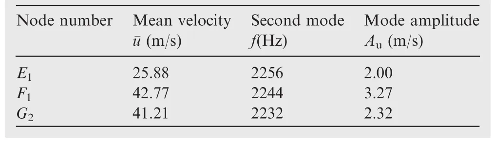
Table 1 Unsteady flow tested by hotwire.17
In which,the variableAeis the effective flow area of swirler,Kis a constant,q(λ)is aerodynamic function value,ccris critical sound speed,γ is the ratio of specific heat,Ris the gas constant,P*andT*represent total pressure and total temperature respectively.
Wall-adapting local eddy viscosity(WALE)subgrid-scale model was applied.In order to reduce the convergence time,initial solution was first obtained by RANS and then imported into LES simulation.In order to validate the LES,flow velocity and its components in three directions at several positions(includingE1,F1,G2)were recorded at each time step in LES.The sample time step was 1×10⁻⁵s and 0.2 million time steps were recorded.

Fig.6 Grid independence validation using RANS results.

Fig.7 Unsteady flow velocity spectrum at position of F1node obtained from LES.

Table 2 Unsteady flow predicted by LES.
Velocity spectrum at position ofF1node obtained from LES is illustrated in Fig.7.Two flow modes can be distinguished from the spectrum as well.The first mode was 1116 Hz with amplitude of 2.01 m/s and the second mode was 2224 Hz with amplitude of 1.99 m/s.Compared with the hotwire test result,the frequency simulation deviation is about 0.8%.However,the amplitude simulation deviation is quite large.The simulation result of amplitude of the first mode was an order larger than test,and the second mode was near half smaller than test.This large deviation on amplitude would be due to the initial background flow obtained from RANS.This phenomenon could be explained as that the energy switched between 1st mode and 2nd mode.Hirshi et al.20once found out that the initial trigger condition has a great influence on the motion in the nonlinear system,which manifests itself in the form of different amplitudes.Unsteady velocity information at positionsE1,F1,G2is listed in Table 2.The second mode frequency simulation deviated from test results less than 1.4%.Although the amplitude simulation deviated greatly away from test result,the spatial distribution of oscillation amplitude was familiar with test.In total,unsteady flow mode in TeLESS swirl can be captured by LES.As the second flow mode dominates in the hotwire test,this mode will be used for analysis in discussion.
4.Discussion
This section discusses the basic features of flow velocity fluctuation,the reason leading to those features and the influence of precessing motion on swirl flow stability.
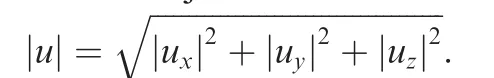
A spiral isobaric surface(99500 Pa)selected at arbitrary time in the pilot passage is illustrated in Fig.9,and this asymmetric structure is referred as precessing vortex core(PVC).21,22Question is raised as to whether the periodic velocity fluctuation atF1node is caused by this precessing motion.Velocity spectrums and phase relationships at four special positions(S1,S2,S3,S4)in pilot passage are analyzed,these four position and the corresponding spectra are illustrated in Fig.10.Velocities at positionsS1andS2re flect the unsteady flow features in 1st swirl of pilot stage,while theS4re flects feature in 2nd swirl.The velocity at positionS3represents the shear layer’s feature.

Fig.8 Phase relationship between flow velocity u and its three direction velocity components ux,uy,uz(LES result).
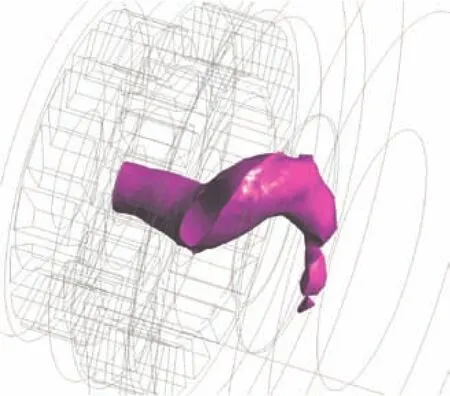
Fig.9 Isobaric surface(99500 Pa)at arbitrary time(LES result).
Unsteady flow modes of 1120 Hz and 2244 Hz both can be seen in 1st and 2nd swirl passage;however,the amplitude at 1st swirl was almost an order larger than 2nd swirl.This phenomenon indicates that the velocity fluctuation in 2nd swirl was induced by the background pressure fluctuation which was caused by the precessing motion in 1st swirl passage.The phenomenon that the amplitude atS1is smaller thanS2implies that the precessing motion was in initial period atS1and reached full development atS2.The amplitude atS3was sharply reduced compared withS2’s,which shows that flow shear between 1st and 2nd swirl had significant damping effect on precessing motion.Finally,the precessing motion intensity decayed convectively as the amplitude atF1was smaller thanS3.The phase relationships(Fig.10(f))betweenS2,S3andF1depict the axial convective feature.
Swirl flow stability and criteria were studied and proposed by Rayleigh23:
(1)The swirl flow is stable when tangential momentum moment ρwrincrease along radial direction.
(2)The swirl flow is neutrally when ρwrkeeps constant along radial direction.
(3)The swirl flow is unstable when ρwrdecrease along radial direction.
Fig.10 Unsteady flow features in pilot passage(LES result).
A modified Richardson number(Ri*)is proposed by Beer et al.24to describe the stability of swirl flow system.The system becomes stable ifRi*is larger than zero.The radial distributions of ρwrat different phases at the position ofx=2 mm(passing throughF1node)are illustrated in Fig.11.Rpis the radius of pilot outlet(see Fig.3).It can be found out that there are four flow characteristic regions in pilot swirl flow.In the region of 0 <r/Rp< 0.35,the gradient d(ρwr)/dralmost kept zero,which indicates that free vortex existed.In the region of 0.35 <r/Rp< 0.5,d(ρwr)/drkept positive,which indicates that the flow was stable and the flow behaved as solid rotation.However,in the region of 0.5<r/Rp< 0.9,d(ρwr)/drturned to negative,which indicates that the flow was unstable.This is because that the full development of precessing motion would bring flow system into unstable.Due to the boundary layer flow,the gradient d(ρwr)/drturned back to positive.And the negative minimum of ρwrcorresponds to the maximum velocity fluctuation amplitude.These two phenomena indicate that there was little effect of precessing motion on boundary layer flow.
The reference25has mentioned that the PVC rotates around recirculation zone,sheds and convects along stream line where axial velocity equals zero.That is,once there was PVC in the swirl flow,the position whereux=0 around recirculation zone represents the PVC position.Velocity ratiouz/uxis introduced here to estimate the radial position of PVC.Asux→0,uz/uxbecame the largest.The reason why applying componentuzis that this component fluctuated strongest.The radial distributions of velocity ratio at different phase are illustrated in Fig.12.It shows that the values and radial positions of(uz/ux)maxat each phase were different,that is,the position of PVC at each phase was different.By comparing Figs.11(a)and 12,it shows that the velocity atF1became larger when the PVC approachesF1.Another interesting phenomenon is that the PVC rotated around axisymmetric line at nonuniform angular velocity.The positions of(uz/ux)maxat phase 0°,144°and 216°are marked in Fig.12 asT1,T2andT3respectively.Seen from Fig.12,the total radial displacement of PVC was 0.14 at processT1→T2→T3,while the displacement was 0.03 at processT3→T1.The mean radial displacement rates ΔS/ΔTof PVC at different process are list in Table 3.The variable ΔSrepresents normalized total radial displacement,ΔTrepresents the normalized time spent at each process,φ is the phase angle.The subscript ‘‘i” and ‘‘j” representT1,T2orT3.

Seen from Table 3,the mean radial displacement rate at processT1→T2→T3was 0.217,while the rate at processT3→T1was 0.075.It indicates that the PVC would rotate around axisymmetric line intermittently.This intermittency would be caused by the asymmetric radial vessel of pilot inlet.However,the intermittent motion did not affect the sinusoidal flow feature atF1position.The intermittency phenomenon was also observed by Dawson et al.26,27
The hotwire test results obtained under non-reacting flow condition are valuable.A large number of tests under reacting flow conditions with different combustor inlet temperature,inlet pressure,fuel–air-ratio and fuel-stage-ratio have been conductedforTeLESScombustor.28,29ThePVC mode appeared in some reacting flow cases,while disappeared in other reacting flow cases.This phenomenon was similar to Syred’s work.14Fig.13 shows the dynamic pressure spectrum obtained from one of the reacting flow tests,the ordinatep′represents pressure oscillation component.The specturm can be distinguished by two kinds of movements.The one is combustor acoustic resonant(822 Hz)and its harmonic resonant,and the other one is PVC motion(2192 Hz).The detailed information about reacting flow test for TeLESS can be found in reference.28

Fig.11 Radial distributions of ρwr at different phases at the position of x=2 mm(LES result).

Fig.12 Radial distributions of velocity ratio at different phases(LES result).

Fig.13 Dynamic pressure spectrum under reacting flow condition for TeLESS combustor.(Inlet temperature is 750 K,inlet pressure is 1.1 MPa,air mass flow rate is 0.95 kg/s,fuel–air-ratio is 0.023,fuel-stage-ratio is 43%).
5.Summary
Unsteady flow feature and its mechanism in TeLESS stratified swirl flow were investigated by combining hotwire measurement and large eddy simulation and several conclusions are listed as follows:
(1)Unsteady flow modes of 1126 Hz and 2244 Hz at pilot outlet were found in the hotwire test and unsteady flow was dominated by 2244 Hz mode.The velocity fluctuation intensity decayed convectively.And the maximum intensity occurred near pilot outlet shear layer.
(2)Mechanism of unsteady flow mode was investigated through LES method.The mesh dimension and time resolution were set based on the hotwire test results.The mode frequency prediction deviated from test by less than 1.4%.Although the mode amplitude prediction deviated largely from test,the predicted spatial distribution of fluctuated amplitude was similar to test results.
(3)The spiral structure of isobaric surface(99500 Pa)indicates that there was precessing vortex core in the pilot stage passage.Unsteady velocity spectra at several special positions were discussed.The periodic flow at the pilot outlet would be caused by the precessing motion.And the shear between 1st and 2nd counter swirl flow in pilot had a distinct damping effect on precessing motion.
(4)Different flow features existed along radial direction.The negative gradientd(ρwr)/drindicated that the swirl flow was unstable.
(5)The variation of velocity ratio distribution at different phases indicates that the PVC rotated intermittently.
(6)The PVC motion frequency under non-reacting flow condition is slightly different from the frequency under reacting flow condition.Consequently,the investigation conducted under the non-reacting flow condition is meaningful and economical.
(7)The PVC motion would be a potential mechanism affecting the unsteady heat release,which depends on the fuel supply condition.To eliminate PVC’s negative effects,it requires reducing the swirl number of pilot’s 1st stage to decrease the PVC intensity as suggested in reference.14
Acknowledgement
Thanks for AVIC Commercial Aircraft Engine Co.,Ltd.’s support on combustion instability investigation.
1.Smith R.Advanced low emissions subsonic combustor study.Washington,D.C.:NASA;1998.Report No.:CR-1998-207931.
2.Kuentzmann P.Report of the independent experts to CAEP/8 on the second NOXreview&long term technology goals.Montreal,Canada:ICAO;2010.Report No.:Doc-9953.
3.Lieuwen TC,Yang V.Combustion instabilities in gas turbine engines.Reston:AIAA;2005.
4.Huang Y,Yang V.Dynamics and stability of lean-premixed swirlstabilized combustion.ProgEnergyCombustSci2009;35(4):293–364.
5.Fu ZB,Li JB,Lin YZ.Experimental investigation on ignition performance of LESS combustor.Proceedings of the ASME turbo expo.Vancouver,Canada.New York:ASME;2011.
6.Lee HJ,Kim KT,Lee JG,Quay BD,Santavicca DA.An experimental study of the coupling of combustion instability mechanisms in a lean premixed gas turbine combustor.Proceedings of the ASME turbo expo.Orlando,USA.New York:ASME;2009.
7.Lieuwen T,Neumeier Y,Zinn BT.The role of unmixedness and chemical kinetics in driving combustion instabilities in lean premixed combustor.Combust Sci Technol1998;135(1–6):193–211.
8.Lee JG,Kim K,Santavicca DA.Measurement of equivalence ratio and its effect on heat release during unstable combustion.Proc Combust Inst2000;28(1):415–21.
9.Nguyen QV.Measurements of equivalence ratio fluctuations in a lean premixed prevaporized(LPP)combustor and its correlation to combustion instability.Proceedings of the ASME turbo expo.Amsterdam,Netherlands.New York:ASME;2002.
10.Huang Y,Yang V.Bifurcation of flame structure in a leanpremixed swirl stabilized combustor:Transition from stable to unstable flame.Combust Flame2004;136(3):383–9.
11.Sengissen AX,Giauque AV,Staffelbach GS,Porta M,Krebs W,Kaufmann P,et al.Large eddy simulation of piloting effects on turbulentswirling flames.ProcCombustInst2007;31(2):1729–36.
12.Bellow BD,Bobba MK,Seitzman JM,Lieuwen T.Nonlinear flame transfer function characteristics in a swirl-stabilized combustor.J Eng Gas Turbines Power2007;129(4):954–61.
13.Balachandran R,Ayoola BO,Kaminski CF,Dowling AP,Mastorakos E.Experimental investigation of the nonlinear response of turbulent premixed flames to imposed inlet velocity oscillations.Combust Flame2005;143(1):37–55.
14.Syred N.A review of oscillation mechanisms and the role of the precessing vortex core(PVC)in swirl combustion systems.Prog Energy Combust Sci2006;32(2):93–161.
15.Steinberg AM,Arndt CM,Meier W.Parametric study of vortex structures and their dynamics in swirl-stabilized combustion.Proc Combust Inst2013;34(2):3117–25.
16.Palies P,Durox D,Schuller T,Candel S.The combined dynamics of swirlers and turbulent premixed swirling flames.Combust Flame2010;157(9):1698–717.
17.Qin H,Ding ZL,Li HT,Lin YZ,LI JB.Unsteady swirling flow in low emissions stirred swirls(LESS)combustor.J Aerosp Power2015;30(7):1566–75[Chinese].
18.Zhang M,Fu ZB,Lin YZ,Li JB.CFD study of NOXemissions in a model commercial aircraft engine combustor.Chin J Aeronaut2012;25(6):854–63.
19.Qin H,Ding ZL,Lin YZ,Li JB.Dynamic response characteristic of concentric stage swirling structure.J Aerosp Power2015;30(4):793–9[Chinese].
20.Hirshi G,Hiroyuki N,Takaya M,Shigeru T.Dynamic properties of combustion instability in a lean premixed gas-turbine combustor.Chaos2011;21(1):013124–13134.
21.Wang S,Yang V,Hsiao G,Hsieh SY,Mongia HC.Large eddy simulation of gas turbine swirl injector flow dynamics.J Fluid Mech2007;583:99–122.
22.Roux S,Lartigue G,Poinsot T,Meier U,Berat C.Studies of mean and unsteady flow in a swirled combustor using experiments,acoustic analysis and large eddy simulations.Combust Flame2005;141(1):40–54.
23.Rayleigh L.On the stability of stratified flow.Proc R Soc London1916;93:148–58.
24.Beer JM,Chigier NA,Davies TW,Bassindale K.Laminarization of turbulent flames in rotating environments.Combust Flame1971;16:39–45.
25.Syred N,O’Doherty T,Froud D.The interaction of the precessing vortex core and reverse flow zone in the exhaust of a swirl burner.J Power Energy1994;208(1):27–36.
26.Dawson JR,Rodrigues-Martinez VM,Syred N,O’Doherty T.The effect of expansion plane geometry on fluid dynamics under combustion instability in a swirl combustor.Proceedings of 41st AIAA aerospace sciences meeting and exhibit.Reno,Nevada.Reston:AIAA;2003.
27.Dawson JR,Rodrigues-Martinez VM,Syred N,O’Doherty T.The effect of combustion instability on the structure of recirculation zones in confined swirling flames.Combust Sci Technol2005;177(12):2349–71.
28.Qin H,Tang GQ,Lin YZ,Li JB.Influence of fuel stage ratio on pressure oscillation frequency of LESS combustor.J Aerosp Power2015;30(6):1337–43[Chinese].
29.Qin H,Fu ZB,Lin YZ,Li JB.Investigation on liner structure optimization based on pressure oscillation in combustors.J Aerosp Power2015;30(5):1076–83[Chinese].
23 January 2015;revised 27 July 2015;accepted 30 October 2015
Available online 23 February 2016
ⓒ2016 Chinese Society of Aeronautics and Astronautics.Published by Elsevier Ltd.This is an open access article under the CC BY-NC-ND license(http://creativecommons.org/licenses/by-nc-nd/4.0/).
*Corresponding author.Tel.:+86 10 82316847.
E-mail addresses:hao916200@163.com(H.Qin),linyuzhen@buaa.edu.cn(Y.Lin),li9403@hotmail.com(J.Li).
Peer review under responsibility of Editorial Committee of CJA.
Qin Haois a Ph.D.candidate at School of Energy and Power Engineering,Beihang University.His area of research includes unsteady swirling flow,flame dynamics and combustion instability.
Lin Yuzhenis a professor and Ph.D.supervisor at School of Energy and Power Engineering,Beihang University.His main research interests are low emission combustion,combustion instability and supersonic combustion.
Li Jibaois the vice president and the chief engineer of AVIC Commercial Aircraft Engine Co.,ltd.He is the project leader of civil aeroengine.
杂志排行

CHINESE JOURNAL OF AERONAUTICS的其它文章
- Hypersonic starting flow at high angle of attack
- Advances and trends in plastic forming technologies for welded tubes
- Instability and sensitivity analysis of flows using OpenFOAM®
- Numerical simulations of high enthalpy flows around entry bodies
- Modeling and simulation of a time-varying inertia aircraft in aerial refueling
- Experimental investigations for parametric effects of dual synthetic jets on delaying stall of a thick airfoil