Plastic wrinkling model and characteristics of shear enforced Ti-alloy thin-walled tubes under combination die constraints and diff erential temperature fields
2016-11-23YanJing
Yan Jing
Aeronautical Key Laboratory for Plastic Forming Technology,Beijing 100024,China
Beijing Key Laboratory of Digital Plastic Forming Technology and Equipment,Beijing 100024,China
Beijing Aeronautical Manufacturing Technology Research Institute,Beijing 100024,China
Plastic wrinkling model and characteristics of shear enforced Ti-alloy thin-walled tubes under combination die constraints and diff erential temperature fields
Yan Jing*
Aeronautical Key Laboratory for Plastic Forming Technology,Beijing 100024,China
Beijing Key Laboratory of Digital Plastic Forming Technology and Equipment,Beijing 100024,China
Beijing Aeronautical Manufacturing Technology Research Institute,Beijing 100024,China
Plastic wrinkling predictions and shear enforced wrinkling characteristics of Ti-alloy thin-walled tubes under combination die constraints have become key problems urgently in need of solutions in order to improve forming quality in their shear bending processes under differential temperature fields.To address this,a wrinkling wave function was developed by considering their shear bend deformation characteristics.Based on this wave function and the thin shell theory,an energy prediction model for this type of wrinkling was established.This model enables consideration of the effects of shear deformation zone ranges,material parameters,loading modes,and friction coefficients between tube and dies on the minimum wrinkling energy.Tube wrinkling sensitive zones(WSZs)can be revealed by combining this wrinkling prediction model with a thermalmechanical coupled finite element model for simulating these bending processes.The reliability of this wrinkling prediction model was verified,and an investigation into the tube wrinkling characteristics was carried out based on the experimental conditions.This found that the WSZs are located on either a single side or both sides of the maximum shear stress zone.When the friction coefficients between the tube and the various dies coincide,the WSZs are located on both sides.The larger the value of the tube inner corner radius and/or the smaller the value of the outer corner
1.Introduction
As a compact,light-weight component with high strength and performance,Ti-alloy thin-walled tubes with ultrasmall bend radii(bend radii and tube diameter ratios<1)integrate structural and material advantages in a way that makes them be widely applicable to aerospace,aviation and related high technology industries.Tube bending is a key technology for manufacturing tube parts,and it has shown a tendency to focus its development on these Tialloy thin-walled tubes.1In contrast to the existing rotary draw bending2–5and push bending,6a shear bending process under differential temperature fields,as shown in Fig.1,has provided an innovative solution to enable the manufacturing of these Ti-alloy thin-walled tubes while decreasing yield strength and improving formability.

Fig.1 Shear bending process of Ti-alloy thin-walled tube under differential temperature fields.

Fig.2 Tube shear enforced wrinkling.7,8
In Fig.1,a tube is bent first by shear force.After passing along die corners,its bend deformation zone transforms into a vertical segment that enables the transfer of shear force to the tube blank.This vertical segment is subjected to a shear stress where there is an evident shear deformation zone.Both sides of the shear deformation zone are subjected to a compressive stress respectively,and thus the tube can possibly wrinkle.Fig.2 shows the tube’s shear enforced wrinkling defects.7,8The probability of tube wrinkling grows with the increases in tube diameter and decreases in bend radius.The tube forming processes need combination dies and differential temperature fields to act in coordination.Thus,the plastic wrinkling predictions and shear enforced wrinkling characteristics of Ti-alloy thin-walled tubes have become problems that urgently need to be solved in order to improve forming quality and achieve forming limits in these shear bending processes.A great deal of research about the predictions of shear enforced wrinkling has been carried out mainly in plates or membranes under simple boundary conditions,9–12however,there are hardly any published studies on the plastic wrinkling predictions of shear enforced tubes under combination die constraints and differential temperature fields.
Over the last several decades,three kinds of methodologies have been used for determining the critical conditions of wrinkle onset in order to predict plastic wrinkling in sheet and/or tube metal forming processes.These consist of an experimental approach,a bifurcation theory and an energy method.
(1)The experimental approach is based on critical wrinkling displacement or strain fields measured online in metal forming processes.Yoshida13developed a buckling test,and the critical amplitudes of buckling are measured to estimate a sheet’s anti-wrinkling abilities in an unequal stretch process.Narayanasamy and Loganathan14studied the wrinkling in the deep drawing process of circle cup parts without blank holding pressure constraints,and the critical hoop strains and radial strains ratios of wrinkling zones had been used for estimating wrinkling.
(2)The bifurcation theory is based on the bifurcation functionals proposed by Hill15or Hutchinson16.When the solutions of their variation equations are nonzero,wrinkling occurs.Kim et al.17–19combined Hill’s bifurcation theory and a continuation method proposed by Riks20for post bifurcation analysis along a secondary solution path with an implicit finite element(FE)code.The deep drawing process of a cone part and the Yoshida buckling test process were simulated by using this modified code,and the critical displacement fields in these two processes had been acquired.Chu and Xu21simplified the sheet deep drawing process as a two dimensional problem,and analyzed the critical wrinkling stresses by using the bifurcation theory.Based on Hutchinson’s functional,Abbasi et al.22analyzed the flange of tailor welded sheets,and Pourmoghadam et al.23analyzed the critical blank holding pressures of anisotropic laminated sheets.Ravindra and Dixit24combined Hill’s functional with the implicit FE method,and considered the determinants of the coefficient matrixes of its variation equations as the critical wrinkling conditions of the flanges of square cup parts.
The explicit FE method enables simulations of post bifurcation behaviors along a secondary solution path in forming processes,and its essence is also based on the bifurcation theory.This method enables the determination of critical displacement and/or strain fields,and its prediction precision mainly depends on element types,meshing densities and the initial imperfection of geometric shapes.25–27The increases in the meshing densities and the introduction of initial imperfection have been able to improve wrinkling prediction precision,but both ways have increased FE analysis time costs.The shear bending processes of Ti-alloy thin-walled tubes under differential temperature fields are typical thermal-mechanical coupled processes,and the improvement of computational efficiency has been a challenging issue in their simulations.
(3)The energy method assumes that the wrinkling occurs when the minimum wrinkling energy of the sheets and/or shells ΔUminequals the work done by the external forces ΔW.Yu et al.28,29analyzed critical wrinkling stresses of the flanges of circle cup parts.Cao et al.30,31analyzed those flanges and the side walls of cone parts.Morovvati et al.32analyzed those of two-layer sheets.The energy method has been more effective in establishing the critical conditions of wrinkling onset in thin shell metal forming processes compared with the bifurcation theory.Sun and Yang33established critical forming forces in the tube axial compressive processes.Wang and Cao34predicted the wrinkling in the numerical control(NC)bending processes of small diameter tubes based on the Donnell-Mushtari-Vlasov shell theory.Yang and Lin35analyzed the critical bend radii in the NC bending processes of different diameter tubes based on the more precise wrinkling wave function.Liu et al.36analyzed the critical wrinkling stresses of side walls in the hydroforming processes of thin-walled tube teejoints.
It is difficult to simulate these post bifurcation behaviors by only using the implicit FE method,and thus it is necessary to combine established critical conditions with the FE code for wrinkling predictionsin forming processes.Wang and Cao37,38predicted the wrinkling by combining the critical wrinkling stresses with the implicit FE model for simulating the deep drawing processes.Lin et al.39combined the wrinkling energy model with the rigid-plastic FE model for simulating the tube NC bending processes,and first predicted the tube wrinkling by using the wrinkling factor ΔW/ΔUminfor indicating the tube wrinkling probability.By combining the wrinkling energy model under multi-die constraints with the dynamic explicit FE model for simulating the NC bending processes of large diameter thin-walled aluminum alloy tubes,Li and Yang et al.40,41revealed the tube wrinkling sensitive zones(WSZs)and predicted the tube wrinkling accurately and eff iciently by using the wrinkling factor.They found that this wrinkling index is insensitive to both the mesh densities and initial imperfection.In addition,this index considers comprehensively the effects of both critical wrinkling stresses and the WSZs on wrinkling to enable more accurate descriptions of material wrinkling characteristics in forming processes.
Ti-alloy thin-walled tubes are covered by combination dies in their shear bending processes under differential temperature fields,and thus it is difficult to measure the critical displacement and/or strain fields of their wrinkling online.Critical conditions determined only by using an analytical approach cannot consider the effects of several vital parameters of wrinkling,such as the WSZs,and the complicated thermalmechanical coupled dynamic contact behaviors between the tubes and the various dies.It is also difficult to solve these complicated contact problems by using the implicit FE method due to the deteriorated convergence in each iteration procedure.Thus,a wrinkling wave function was developed by considering the tube shear bend deformation characteristics.Based on this wave function and the thin shell theory,an energy prediction model of wrinkling was established,and the wrinkling factor was used for the wrinkling index.The WSZs were revealed by combining this wrinkling prediction model with a thermal-mechanical coupled explicit FE model for simulating tube shear bending processes,and an investigation of their wrinkling characteristics was carried out based on experimental conditions.
2.Research methodology
2.1.Experimental process
Shear bending experiments of the TA2 Ti-alloy thin-walled tubes under differential temperature fields were performed,and the experimental apparatus included forming dies,a cooling system and a hot forming press,as shown in Fig.3.The cooling gas source linked to the forming dies by a metal tube supplying the argon.The thermal physical properties of TA2 tube are listed in Table 1,42and the tube shear stress constitutive parameters in Table 2.43The constitutive equation was defined as¯σ=K(T)¯εn(T)˙¯εm′(T),where¯σ is the equivalent stress,¯ε is the equivalent strain,and˙¯ε is the equivalent strain rate.
A tube and the forming dies were heated by the press platforms,and their temperatures were measured by a thermocouple inserted in a fixing bending die.Transfer mechanisms were the heat conduction between the tube and the dies,the heat convection between the tube and its ambience,mainly the air and the cooling gas flow,and the thermal radiation between them.
The tube blank shown in Fig.4 was used for the prevention of wall thinning.The surfaces of both the half tube with a slope end and the die cavities were lubricated by an air dry solid film lubricant(T50)to decrease the friction coefficients between them,while the surfaces of the other half tube were unlubricated.A tube segment with a length 70 mm from the slope end was inserted into the cavity of the fixing bending die,and the other segment was inserted into the moving die cavities.The experimental parameters are listed in Table 3.
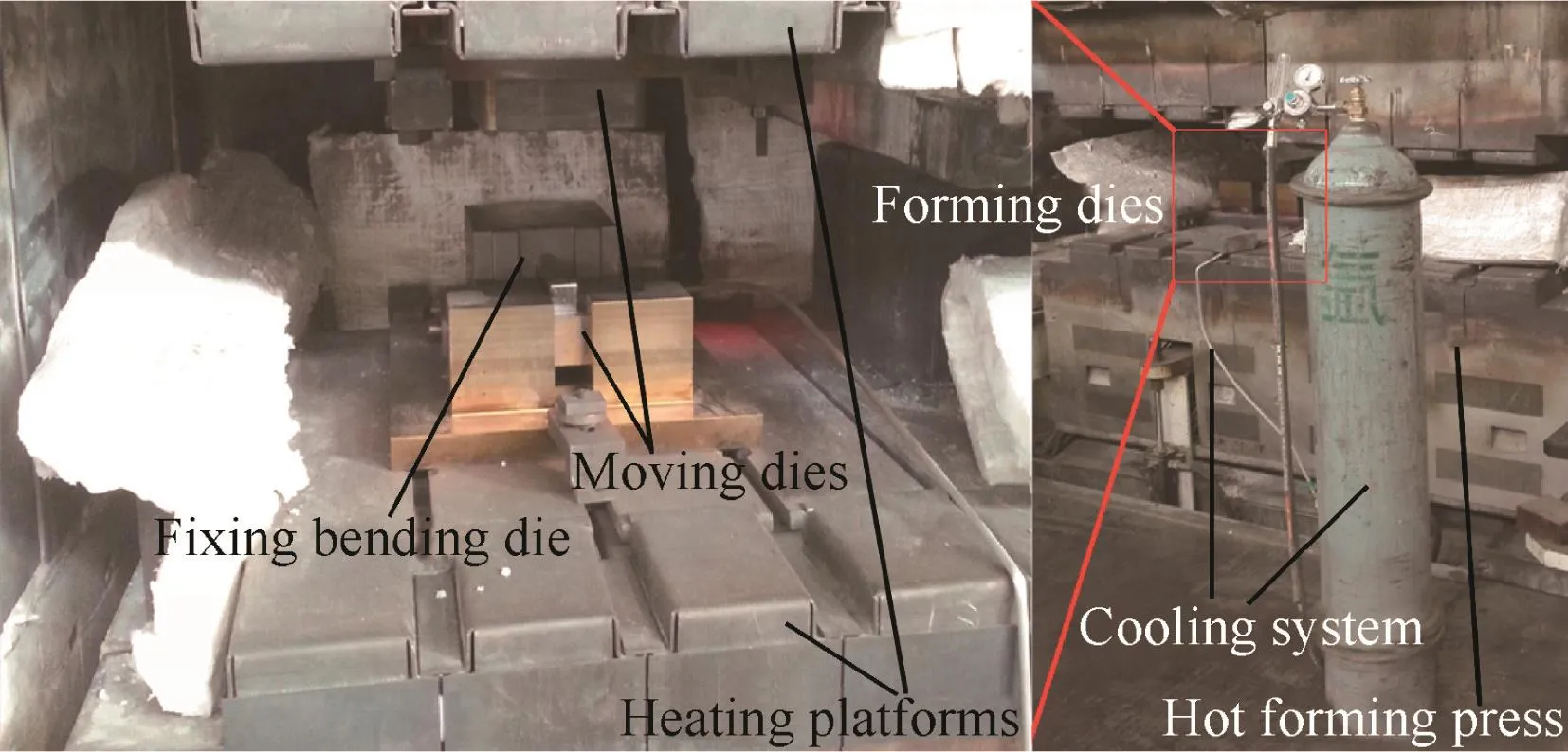
Fig.3 Shear bending apparatus of Ti-alloy thin-walled tubes under differential temperature fields.
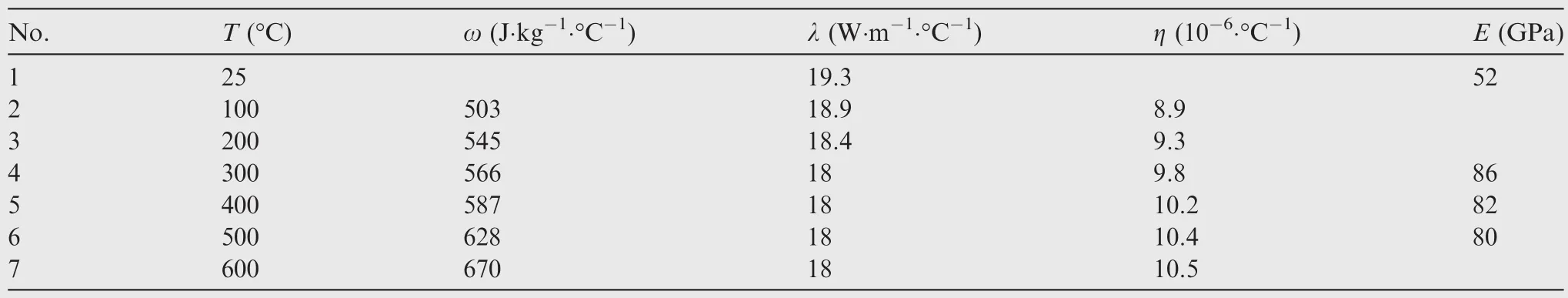
Table 1 TA2 tube thermal physical properties.42
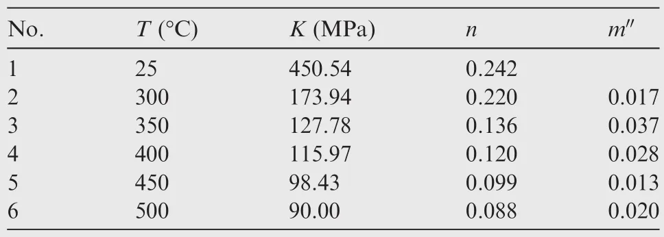
Table 2 TA2 tube shear stress constitutive parameters.43
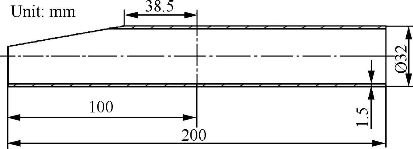
Fig.4 Geometric shape of tube blank.
A tube part is shown in Fig.5,and shear enforced wrinkling can be observed in the vertical tube segment.The tube insertion length was so short that the slope end was not supported by the fixing dies,and only a single side of the vertical segment was loaded by shear force,defined as a single side loading mode(SSLM).The shear deformation material there increased greatly and thus increased shear stress.The larger the shear stress,the larger the compressive stress.As a result,tube wrinkling probability largely increased,and the tube wrinkled.
When the insertion length was changed to 100 mm,both sides of the vertical segment were loaded by shear force,defined as a both sides loading mode(BSLM),and tube part forming was stable,as shown in Fig.6.In this process,both tube ends were supported by the dies without exerting an axial load on the tube end and the like was seen in the literature,7,8and the shear deformation material distributed more evenly there,which prevented the increases in shear stress.Thus,the tube wrinkling probability was smaller than the SSLM.
2.2.FE model
A three dimensional(3D)elastic-plastic thermal-mechanical coupled FE model for simulating shear bending processes of Ti-alloy thin-walled tubes under differential temperature fields was established based on a dynamic,explicit,thermalmechanical module in the ABAQUS software environment.Fig.7 shows a representative FE model for simulating these processes.In this model,the half bodies of a tube and theforming dies’cavities are modeled considering their geometric symmetry.The tube is a deformable body discretized by the 1 mm×1 mm thermal-mechanical,eight-node,doubly curved thin shell elements considering reduced integration and hourglass control.The forming dies are simplified as rigid bodies,with constraints,discretized by the same thin shell elements.
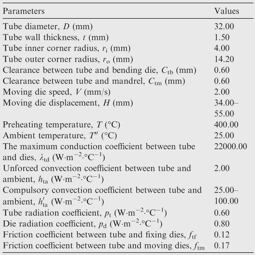
Table 3 Experimental parameters of TA2 tube shear bending processes.
A material model used in the simulation is an isotropic,homogeneous,elastic-plasticmaterialfollowing thevon-Mises yield criterion,with the isotropic work hardening and without the Bauschinger effects taken into account.The relationships between the constitutive parameters and the temperatures are listed in Table 2.
The displacement components of both the fixing bending die and the fixing mandrel are 0 mm along all degrees offreedom,while a shear velocity is exerted on both the moving bending die and the moving mandrel only along the Y direction.The displacement component of the tube’s symmetrical central plane is 0 mm only along the Z direction,and the others are unconstrained.
The contact behaviors between the fixing/moving mandrels and the tube’s inside surface,and/or between the fixing/moving bending dies and the tube outside surface,are simulated by using contact pair algorithms.The tangent behaviors between them are described by the Coulomb friction model.44Friction heat generation was considered in the definitions of the contact properties between them.
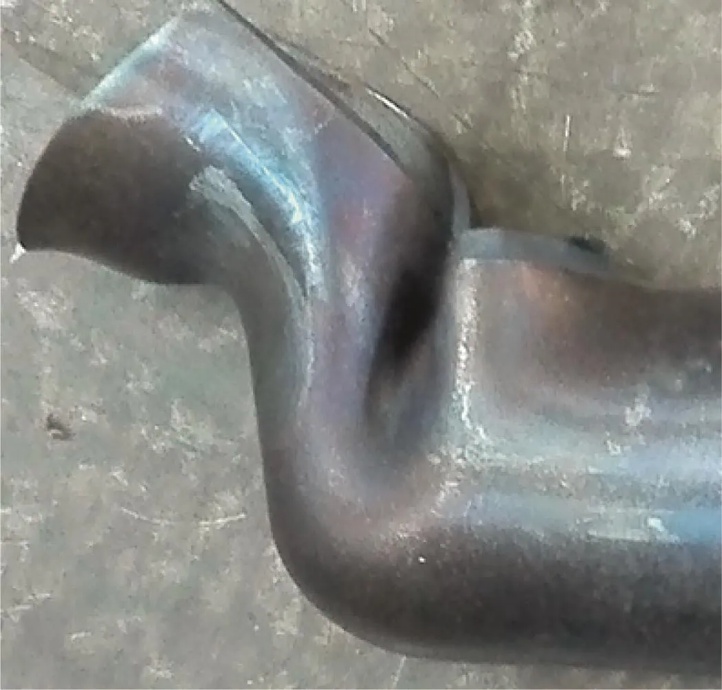
Fig.5 TA2 tube shear enforced wrinkling.

Fig.6 TA2 stable tube forming.
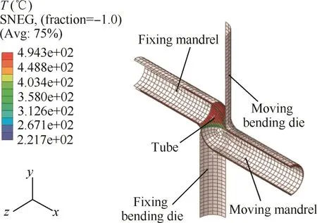
Fig.7 A representative FE model for a Ti-alloy thin-walled tube shear bending process under differential temperature fields.
The values of the initial temperature fields of the tube and the forming dies are the same as their preheated temperatures,and their distributions are simplified for uniformity without considering the thermal resistances of the dies.Simulation of changes in tube temperature fields is performed by defining the heat transfer parameters in the heat conduction processes between the tube and the different dies,the heat convection processes between the tube and its ambience,and the thermal radiation processes between them.The relationship between the ‘clearance” and the ‘conduction coefficient” is used to define heat conduction.Both the ‘temperature difference”and the ‘convection coefficient” are used to define heat convection.The ‘temperature difference” and the ‘radiation coefficient”are used to define thermal radiation.In the literature,43the reliability of this FE model has been verified by the experimental results.
2.3.Wrinkling energy model
2.3.1.Shell energy model
Based on the wrinkling mode of shear enforced Ti-alloy thinwalled tube observed in this experiment,and the thin-shell theory,45a shear enforced wrinkling energy model of a cylinder shell can be established.
The shell model is shown in Fig.8.The range of the shear deformation zone along the X direction is ΔX=X1-X0,and X0is a starting point along this direction of the vertical shear deformationzone.Alongtheθdirection,itsrangeis Δθ = θ1- θ0,and θ0is its starting point.These two starting points are both determined by performing FE analyses of the shear bending processes.
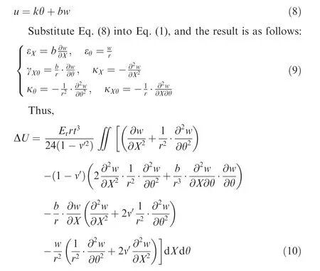
The shell geometrical equation is as follows:
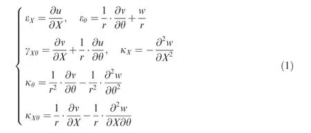
where X,θ,and Z are the curve coordinate systems on the shell middle plane;εX,εθand γXθare the strain components;κX,κθand κXθare the curvature change components;u,v and w are the displacement components;r is the tube radius.
The shear enforced wrinkling energy of the shell is as follows:
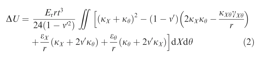

Fig.8 Cylinder shell model.
2.3.2.Wave function of shear enforced wrinkling
According to the literature,35the tube wave function is assumed to satisfy Eq.(3),and its boundary conditions considering X0=0 mm:(1)when X=X0,X=X1-X0,w=0;(2)when X=X0,X=
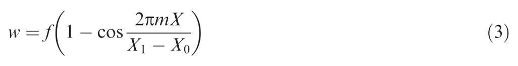
When the range of the vertical shear deformation zone reaches X,the tube becomes wrinkled.According to the small deflection assumption,its displacement along the X direction is as follows:

where R0is the bend radius,and R0=ri+r;Δφ is the range of the maximum tangent compressive stress in the tube intrados determined by performing the FE analyses;m is the wave number;and C is the shear angle as shown in Fig.9.
Thus,
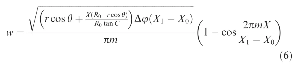
The shear features of the real wrinkling wave are obvious,and so the wave function shown in Eq.(6)needs to be treated as follows:
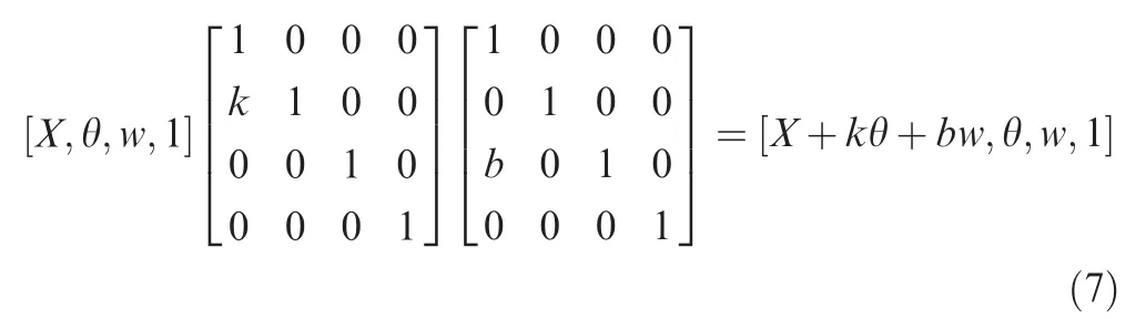
where k>0 and b>0 are the shear coefficients used for indicating the shear deformation degree of the wave along the X direction,and they are determined by performing an analysis of the real wave shape.
Therefore,the effects of both the w and the u should be considered in the shear enforced wrinkling energy model,and according to Eq.(7),
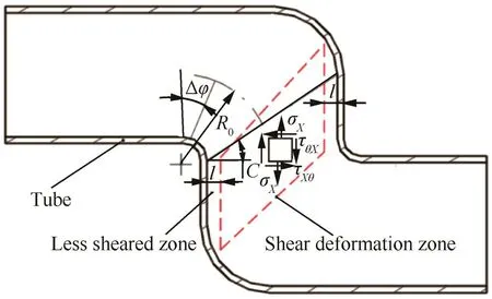
Fig.9 Illustration of tube shear deformation.
2.3.3.Critical wave number
According to the literature,46for the infinitesimal body in the shear deformation zone shown in Fig.8,the following equation can be established when the shear enforced wrinkling occurs:
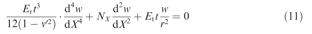
where NXis the membrane force along the X direction in the middle plane.
Substitute Eq.(3)into Eq.(11),and the membrane force is deduced as follows:
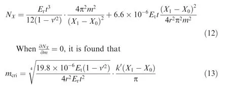
where k′> 0 defines the effects of the shear deformation on the critical membrane force orientation.By substituting Eq.(13)into Eq.(10),the minimum shear enforced wrinkling energy ΔUmincan be determined.
Substitute Eq.(13)into Eq.(12),and the critical stress of shear enforced wrinkling onset is as follows:

From Fig.9,the shear deformation zone is subjected to the tension and shear stresses,and they are calculated respectively by Eqs.(15)and(16).
where σXis the tension stress;τXθis the shear stress;σφis the maximum tangent compressive stress on tube intrados determined by performing the FE analyses of the shear bending processes;l is the length of the less sheared zone7;μ is the average friction coefficient between the tube and the die corners;δ is the load coefficient,defined for the SSLM(1)as δ=1 and for the BSLM(2)as δ=2.
The principle stress in the shear deformation zone is as follows:
When the shear enforced wrinkling occurs,
2.4.Prediction methodology of shear enforced wrinkling
Fig.10 shows the prediction methodology of shear enforced wrinkling.WSZs are determined by combining the FE model for simulating the Ti-alloy thin-walled tube shear bending processes under differential temperature fields with the wrinkling energy model.
The minimum wrinkling energy ΔUminof the WSZs and the work done by the external force ΔW are calculated respectively,and then the wrinkling factor ΔW/ΔUminis determined for measuring the tube wrinkling probability.The critical condition of wrinkling onset is ΔW/ΔUmin≥ 1,otherwise tube formation is stable.Work ΔW is defined as follows:

where m′is the element number of the plastic shear deformation zone;¯σiis element average equivalent stress;¯εiis element average equivalent strain;dViis the element volume.
Fig.10 Prediction methodology of shear enforced wrinkling.
2.5.The minimum wrinkling energy
2.5.1.Wave function parameter identification
Shear angles are determined by measuring the digital 3D geometric models of the Ti-alloy thin-walled tubes with the different diameters,as shown in Table 4.
By the comparing the real wave shape shown in Fig.11 and the wave function shown in Eqs.(6)and(7),the k=50.30,and b=0.58 are determined.Fig.11 shows the comparison between them.It can be found that the wave function enables a reliable description of the real wave shape.
2.5.2.Effect of shear deformation zone range
Fig.12 shows the effects of the shear deformation zone range on the minimum wrinkling energy ΔUmin.It can be found that(1)the larger the ratio of the X direction range and the tube diameter ΔX/D,the smaller the value of ΔUmin;the larger the value of the θ direction range Δθ,the larger the values of ΔUmin,and the larger the ratios of ΔX/D corresponding to thelow energy.FortheBSLM,when ΔX/D>0.80,ΔUmin< 40 J indicating the tube’s small anti-wrinkling abilities(see Fig.12(a)).For the SSLM,when ΔX/D > 0.50,ΔUmin< 40 J(see Fig.12(b)).(2)The values of ΔUminfor the SSLM are smaller than the BSLM,and thus the tube’s anti-wrinkling abilities for SSLM are also smaller.According to Eq.(14),the critical stress for the SSLM is smaller,which indicates reduced anti-wrinkling abilities.Thus,the established critical wave number,mcriis reliable.(3)The smaller the value of ΔX/D,the larger the effects of the θ direction range on the minimum wrinkling energy.
2.5.3.Effect of preheating temperature
Fig.13 shows the effects of preheating temperature T on the minimum wrinkling energy ΔUmin.It can be found that the larger the value of T,the larger the values of ΔUmin,but,the effects of the temperatures are small.The larger the ratio of ΔX/D,the smaller the values of ΔUmin.The smaller the value of T,the smaller the ratios of ΔX/D corresponding to small anti-wrinkling abilities.In essence,the above results reflect the effects of temperature on the constitutive parameters of the TA2 tube(see Table 2).
2.5.4.Effect of tube diameter
Fig.14 shows the effects of the tube diameter D on the minimum wrinkling energy ΔUmin.It can be found that(1)the larger the value of D,the smaller both the values of ΔUminand their changes.(2)With increasing values of D come larger values of Δθ, ΔUminand the effects of the values of Δθ.When D > 70 mm,the increments of ΔUminremain stable.The larger the ratio of ΔX/D,the smaller the value of ΔUmin.(3)Withboth larger values of D and smaller values of Δθ come smaller ratios of ΔX/D corresponding to small anti-wrinkling abilities.

Table 4 Shear angle of Ti-alloy thin-walled tube.
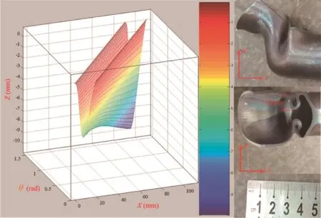
Fig.11 Comparison between wave function and real wave shape.
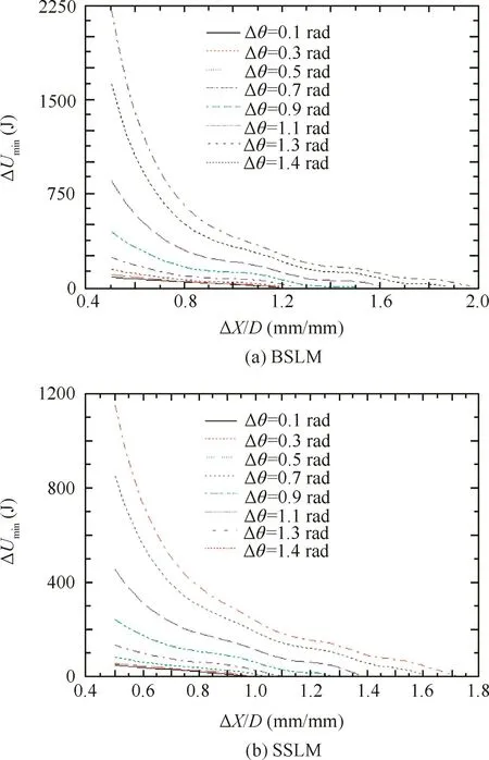
Fig.12 Effect of shear deformation zone range on the minimum wrinkling energy(T=400°C,D=32 mm,t=1.5 mm).
2.5.5.Effect of wall thickness
Fig.15 shows the effects of the wall thickness t on the minimum wrinkling energy ΔUmin.It can be found that(1)the smaller the value of t,the smaller both the values of ΔUminand their changes.(2)With decreases in the value of t come larger values of Δθ and ΔUminand smaller effects of the value of Δθ.The larger the ratios of ΔX/D,the smaller the values of ΔUmin.(3)The ratios of ΔX/D corresponding to small antiwrinkling abilities are not sensitive to the values of t and Δθ.
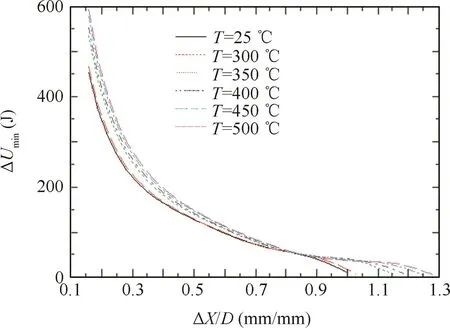
Fig.13 Effect of preheating temperature on the minimum wrinkling energy(D=32 mm,t=1.5 mm).
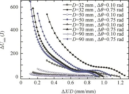
Fig.14 Effect of tube diameter on the minimum wrinkling energy(T=400°C,t=1.5 mm).
Fig.15 Effect of wall thickness on the minimum wrinkling energy(T=400°C,D=32 mm).
2.5.6.Effect of inner corner radius
Fig.16 shows the effects of the inner corner radius rion the minimum wrinkling energy ΔUmin.It can be found that(1)the smaller the value of ri,the smaller the values of ΔUmin,and their changes are basically constant.(2)With decreases in the value of ri,the values of Δθ and ΔUminincrease,and their increments are basically constant.(3)The smaller both the values of riand Δθ,the smaller the ratios of ΔX/D corresponding to small anti-wrinkling abilities.
2.6.WSZs and verifications
Based on the experimental conditions listed in Table 3,the FE model was established for simulating the TA2 tube shear bending processes,and the WSZs ranges corresponding to the maximum wrinkling factor( ΔW/ΔUmin)maxwere determined.
2.6.1.BSLM
Fig.17 shows an illustration of the WSZs searching ranges.It can be found that,for the BSLM,the lower side and the upper part of the tube’s vertical segment are both sheared,and the two sides of the shear deformation zone both have wrinkling possibilities.Thus,the boundaries of the both sides are defined as the 0 points from which the WSZs ranges are searched.
Fig.16 Effect of inner corner radius on the minimum wrinkling energy(T=400°C,D=32 mm,t=1.5 mm).
Fig.17 Illustration of WSZs searching ranges.
Fig.18 Effect of shear deformation zone range on wrinkling factor.
Fig.18 shows the effects of the shear deformation zone ranges on the wrinkling factor ΔW/ΔUmin.It can be found that,with the increase of value in the X direction range ΔX,the ratios of ΔW/ΔUminincrease at first,and then remain stable(see Fig.18(a)).It can be found that,from Fig.18(b),(1)when Δθ ∈ [0.65,1.37]rad,the larger the value of the θ direction range Δθ,the smaller the ratios of ΔW/ΔUminfor both sides;the wrinkling probability of the lower side is less than the upper side.(2)When Δθ ∈ [0.50,0.55]∈ rad,ratios of ΔW/ΔUminwill peak,and the wrinkling probability of the lower side is reduced.(3)When Δθ=0.50 rad,the ratio ΔW/ΔUminof the upper side is at maximum.The reasons for this are that the larger the value of Δθ,the larger the values of the minimum wrinkling energy ΔUmin;when Δθ < 0.50 rad,the increments of the external work ΔW are larger than the ones of ΔUmin,and both the tube slope end and the small friction between the tube and the fixing dies enable decreased contact between them,which means the increments of ΔW on the upper side are larger than the lower side.While Δθ> 0.50 rad,the increments of ΔW are smaller than those of ΔUmin,and thus the ratios of ΔW/ΔUmindecrease gradually.Under experimentalBSLM,the WSZ rangesare determined as Δθ =0.50 rad and ΔX=25.00 mm,located on the upper side.From Fig.19,it can be found that their ranges are basically identical to the maximum shear stress boundaries.(ΔW/ΔUmin)max=0.35 indicates that tube forming is stable,as verified by the experimental result(see Fig.4).
2.6.2.SSLM
For SSLM,shear enforced tube wrinkling was observed in the experiment and was the same as the simulation result of the FE model(see Fig.20).Thus,the established FE model for simulating this process is reliable.The stress-strain fields acquired from the FE analyses enable accurate calculations of the external work ΔW.
From Fig.21,it can be found that,for the SSLM,the WSZ ranges are determined as Δθ =0.75 rad and ΔX=28.00 mm,and their ranges are also basically identical with the boundaries of the maximum shear stress zone(see Fig.22).(ΔW/ΔUmin)max=1.36 indicates that the tube is wrinkling and the prediction result is the same as the experimental one.This is because the increases in the WSZ ranges under the SSLM result in increases in the values of ΔW,and the values of ΔUminare much smaller than in BSLM(see Fig.12(b)).Thus,the ratio of ΔW/ΔUminincreases greatly,and the tube wrinkling probability is higher.
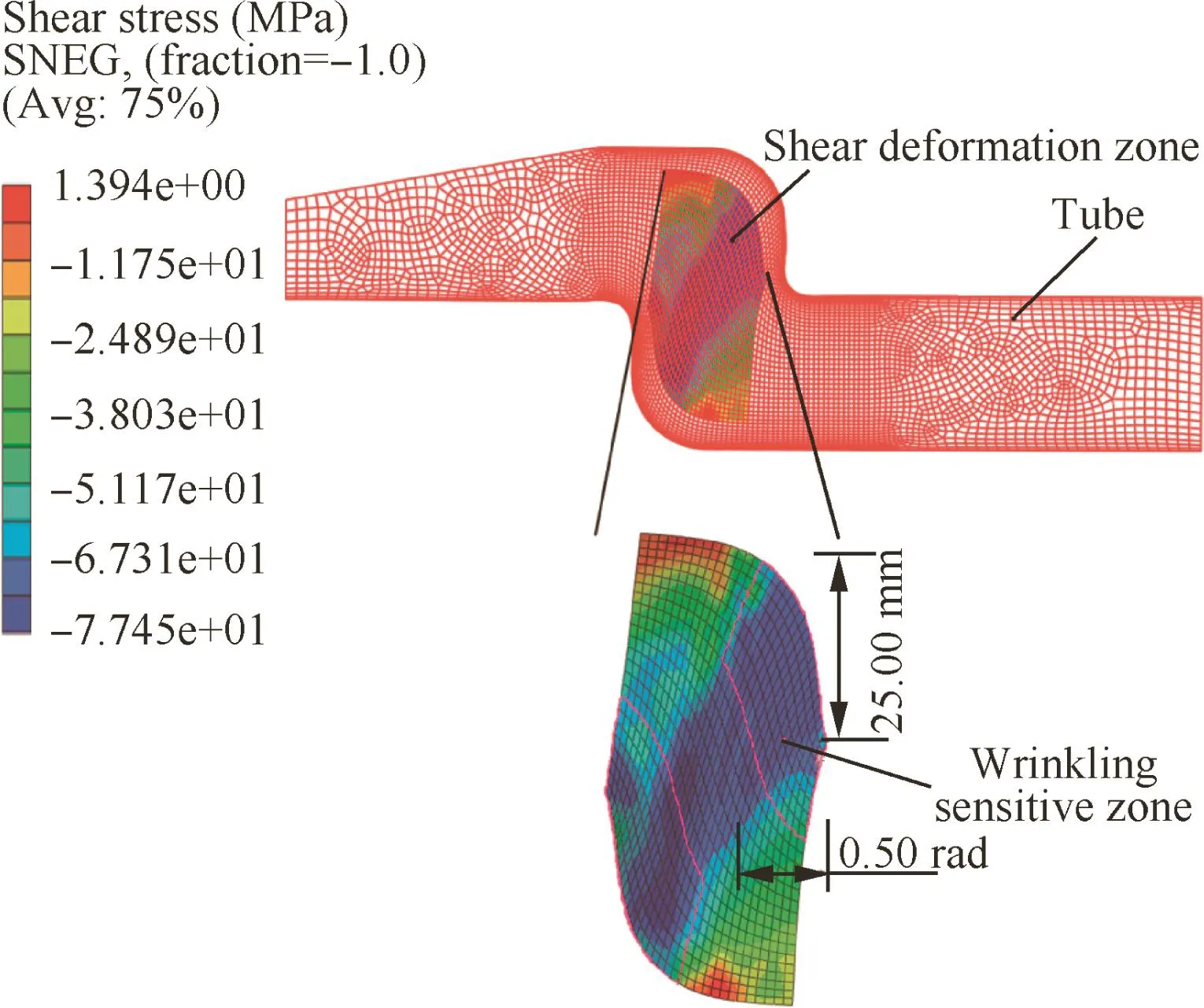
Fig.19 TA2 tube WSZ range for experimental BSLM.
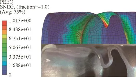
Fig.20 Comparison between simulation and experimental results.
3.Results and discussions
Based on the determined WSZ ranges and the experimental conditions listed in Table 3,the effects of the processing parameters on shear enforced wrinkling characteristics of the TA2 tubes are studied by using a single parameter rotation method.The wrinkling factor ΔW/ΔUminis calculated by using the methodology shown in Fig.10.
3.1.Effect of clearance between tube and mandrel
Fig.23 shows the effects of the clearance between the tube and the mandrel Ctmon the wrinkling factor ΔW/ΔUmin.It can be found that,with the increases in the value of Ctm,the wrinkling possibility first increases and then decreases.When Ctm=0.6 mm,the ratio of ΔW/ΔUminreaches its peak.The reason for this is that when Ctm≤0.6 mm,the increases of Ctmvalue enable decreases in contact interactions between the mandrels and the tubes,and thus change the tube displacement fields of the different zones(see Fig.24).While the displacements of the A zones along the ‘Y” direction increase(see Fig.25(a)),the displacements of the B zones decrease(see Fig.25(b)).The increases in the materials transferring from the A zones to B zones enable the increases in the maximum shear stresses,and thus both the value of the external work ΔW and the ratio of ΔW/ΔUminincrease.When Ctm> 0.6 mm,the contact interactions between the mandrels and the tubes largely decrease,and thus the materials in B zones increase more and more.The unequal deformation degrees around the die corner zones increase greatly,resulting in decreases in the shear forces exerted on the tubes by the mandrels.Thus,the maximum shear stresses decrease,and both the value of ΔW and the ratio of ΔW/ΔUmindecrease.
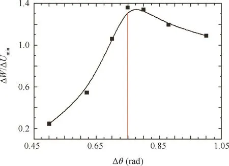
Fig.21 Effect of θ direction range on wrinkling factor.
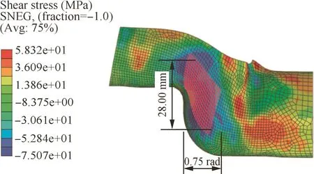
Fig.22 TA2 tube WSZ range for experimental SSLM.
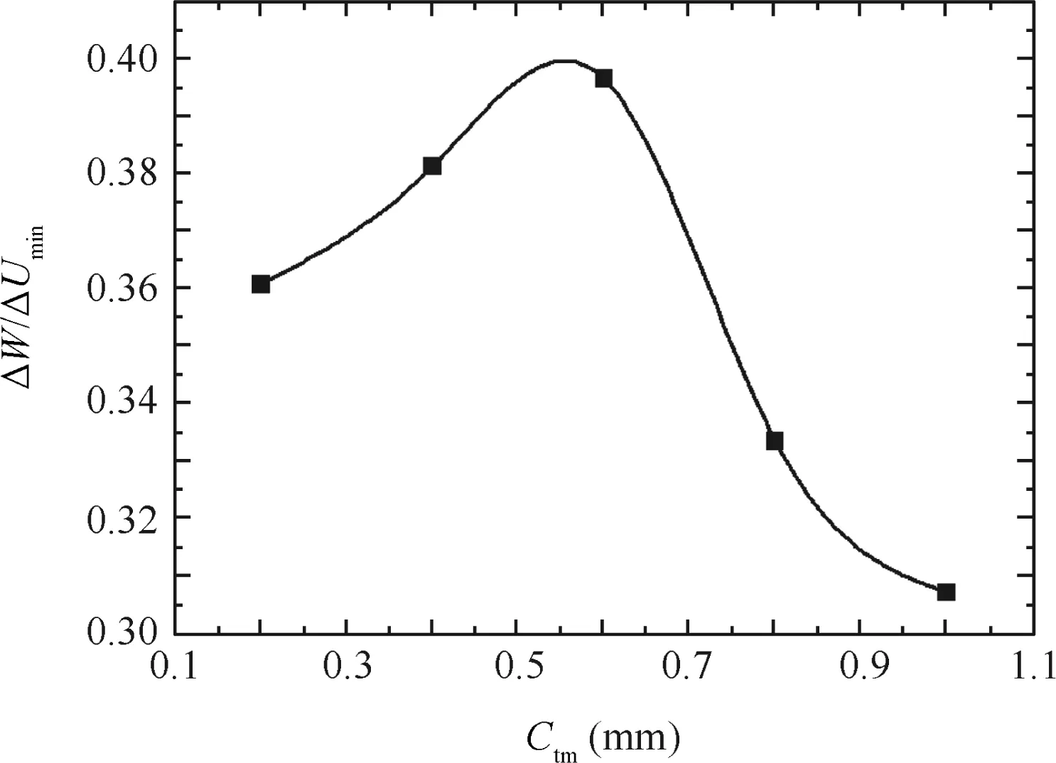
Fig.23 Effect of clearance between tube and mandrel on wrinkling factor.
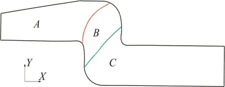
Fig.24 Displacement fields of different zones.

Fig.25 Average displacements of different zones.
3.2.Effect of clearance between tube and bending die
Fig.26 shows the effect of the clearance between tube and bending die Ctbon the wrinkling factor ΔW/ΔUmin.It can be found that,with increasing value of Ctb,the ratio of ΔW/ΔUminat first increases and then decreases,similar to the effect of the value of Ctm.When Ctb=0.6 mm,the ratio of ΔW/ΔUminpeaks.
3.3.Effect of moving die displacement
Fig.27 shows the effects of the moving die displacement H on the wrinkling factor ΔW/ΔUmin.It can be found that with the increases in the value of H,tube wrinkling probability at first increases and then decreases.When H=44 mm,the ratio of ΔW/ΔUminpeaks.This is because when H ≤ 44 mm,larger value of H corresponds to larger value of ΔX,which results in the decreases in the values of ΔUmin(see Fig.12(a)).Meanwhile,larger value of H means more shear deformation materials,which results in increases in both the maximum shear stress and the value of the external work ΔW.As a result,the ratio of ΔW/ΔUminincreases.When H > 44 mm,the degree of wall thinning and the flattening of the tube’s vertical segments both increase,and a necking phenomenon is observed in the experimental process(see Fig.28).This phenomenon enables decreases in the shear forces,and thus both the maximum shear stress and the value of ΔW decrease(see Fig.29).Changes in the value of ΔW are larger than the minimum wrinkling energy ΔUmin,and thus the ratio of ΔW/ΔUmindecreases.
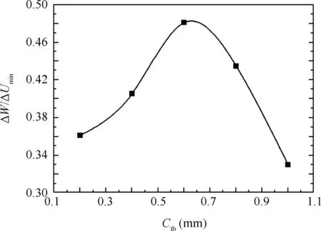
Fig.26 Effect of clearance between tube and bending die on wrinkling factor.
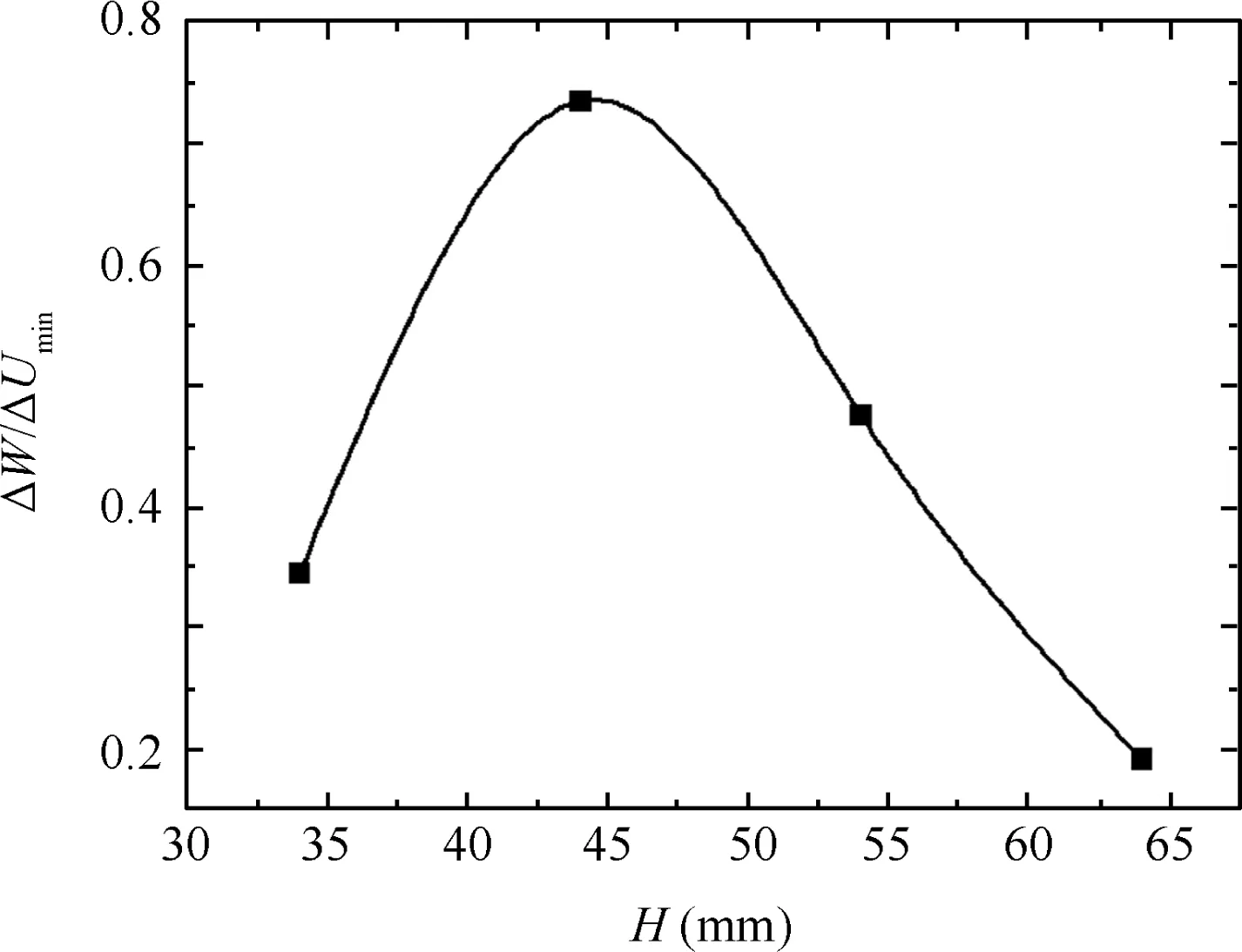
Fig.27 Effect of moving die displacement on wrinkling factor.
3.4.Effect of preheating temperature
Fig.30 shows the effects of the preheating temperature T on the wrinkling factor ΔW/ΔUmin.It can be found that the larger the value of T,the smaller the value of ΔW/ΔUmin.This is because the larger the value of T,the larger the value of ΔUmin(see Fig.13)and the smaller the value of ΔW.
3.5.Effect of outer corner radius
Fig.31 shows the effects of the outer corner radius roon the wrinkling factor ΔW/ΔUmin.It can be found that the smaller the value of ro,the smaller the ratio of ΔW/ΔUmin.This is because the smaller the value of ro,the smaller the interaction areas between the outer corners and the tubes,which enables decreases in the shear forces exerted on the tubes.Thus,decreases in both the maximum shear stress and the value of ΔW enable decreases in the value of ΔW/ΔUmin.
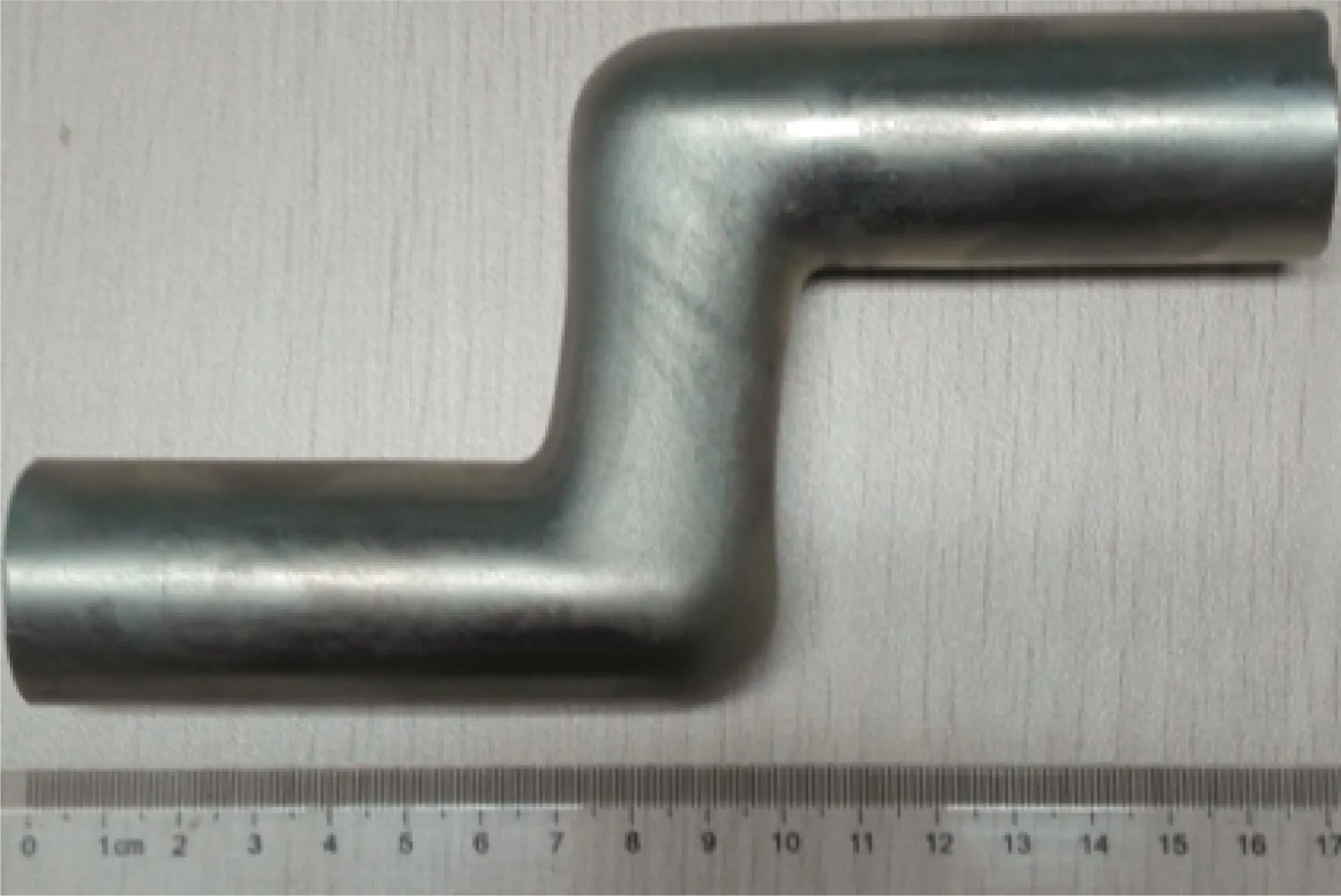
Fig.28 Necking phenomenon(H=55 mm).
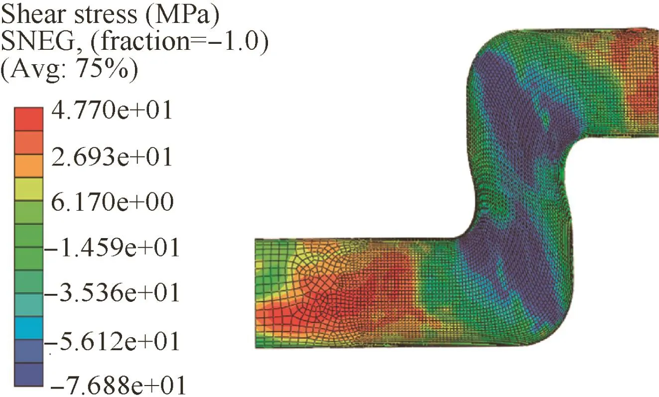
Fig.29 Tube shear stress distributions(H=55 mm).
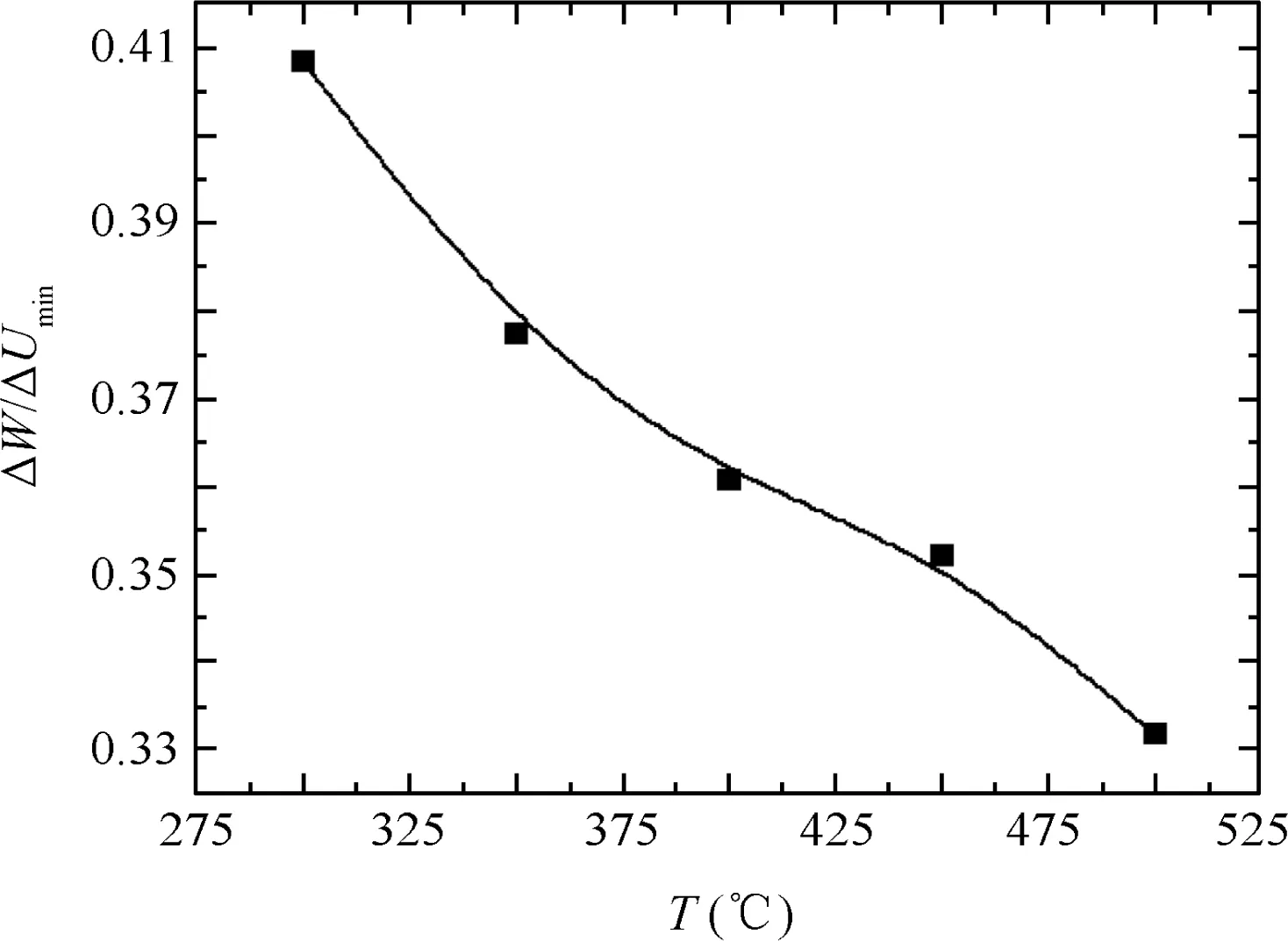
Fig.30 Effect of preheating temperature on wrinkling factor.
3.6.Effect of inner corner radius
Fig.32 shows the effects of the inner corner radius rion the wrinkling factor ΔW/ΔUmin.It can be found that the larger the value of ri,the smaller the ratio of ΔW/ΔUmin.This is because with larger the value of ricomes larger value of the minimum wrinkling energy ΔUmin(see Fig.16);the value of the external work ΔW increases,but the increments of ΔW are smaller than ΔUmin.Thus,the ratio of ΔW/ΔUmindecreases.
3.7.Effect offriction between tube and fixing dies
Fig.33 shows the effects of the friction coefficient between the tube and the fixing dies ftfon the wrinkling factor ΔW/ΔUmin.It can be found that with increases in the value offtf,the ratio of ΔW/ΔUminat first decreases and then increases.When ftf=0.17,the ratio of ΔW/ΔUminis at its minimum.This is because with increases in the value offtf,the materials on the upper sides of the maximum shear stress zones decrease.Thus,decreases in both the maximum shear stress and the value of external work ΔW enable decreases in the ratio of ΔW/ΔUmin.Meanwhile,the shear materials of the lower sides increase.Thus,increases in both the maximum shear stress and the value of ΔW enable the increases in the ratio of ΔW/ΔUmin.As shown in Fig.34,when ftf<0.17,the wrinkling probability of the upper sides is larger than the lower sides;when ftf=0.17,the shear materials of the upper sides are equal to the lower sides,and thus the WSZs are located on the both sides of the shear deformation zones;when ftf>0.17,the wrinkling probability of the upper side is less than the lower side.
3.8.Effect offriction between tube and moving dies
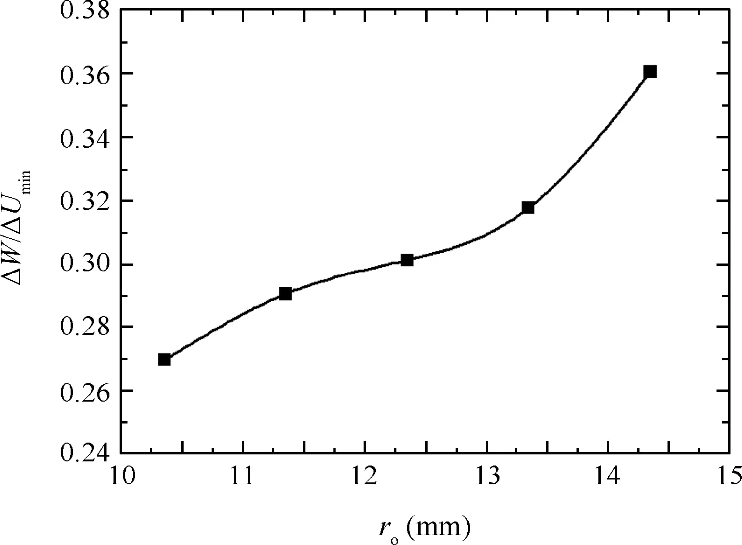
Fig.31 Effect of outer corner radius on wrinkling factor.
Fig.32 Effect of inner corner radius on wrinkling factor.
Fig.33 Effect offriction between tube and fixing dies on wrinkling factor.
Fig.34 Effect offriction between tube and fixing dies on WSZs.

Fig.35 Effect offriction between tube and moving dies on wrinkling factors.
Fig.35 shows the effects of the friction coefficient between the tube and the moving dies ftmon the wrinkling factor ΔW/ΔUmin.It can be found that,with the increases in the value offtm,the ratio of ΔW/ΔUminat first decreases and then increases.When ftm=0.12,the ratio of ΔW/ΔUminis at its minimum.This is because with increases in the value offtm,shear materials on the lower sides of the maximum shear stress zones decrease.Thus,decreases in both the maximum shear stress and the value of the external work ΔW enable decreases in the ratio of ΔW/ΔUmin.Meanwhile,the shear materials of the upper sides increase.Thus,increases in both the maximum shear stress and the value of ΔW enable increases in the ratio of ΔW/ΔUmin.As shown in Fig.36,when ftm< 0.12,the wrinkling probability of the lower side is greater than the upper side;when ftm=0.12,the shear materials of the upper sides are equal to the lower sides,and thus the WSZs are located in the both sides of the shear deformation zones;when ftm>0.12,the wrinkling probability of the upper side is higher than the lower side.
Fig.36 Effect offriction between tube and moving dies on WSZs.
4.Conclusions
(1)Based on the wave function of tube shear enforced plastic wrinkling and the thin shell theory,a reliable energy prediction model for this type of wrinkling was established.This model enables the effects of shear deformation zone ranges,material parameters,loading modes,and friction coefficients between tube and various dies with the minimum wrinkling energy to be considered.
(2)The larger the value of the vertical segment length of the shear deformation zone,the smaller the value of the minimum wrinkling energy;the larger the value of the circum range of the shear deformation zone,the larger the values of both the minimum wrinkling energy and its vertical segment length corresponding to small antiwrinkling abilities;the smaller the value of the vertical segment length,the larger the effects of the circum range on the minimum wrinkling energy.Both the antiwrinkling abilities under the SSLM and the vertical segment lengths corresponding to the small anti-wrinkling abilities are smaller than the BSLM.The larger the value of the preheating temperature,the larger the value of the minimum wrinkling energy,but its increments are small;either larger values of tube diameter or smaller values of wall thickness lead to smaller values of both the minimum wrinkling energy and its increments;the vertical segmentlengthscorresponding to thesmallantiwrinkling abilities are not sensitive to changes of wall thickness and circum range.The smaller the value of the inner corner radius,the smaller the value of the minimum wrinkling energy,and its increments are basically constant.
(3)The WSZs are located in the upper side or both sides of the maximum shear stress zones.When the friction coefficients between the tube and the various dies coincide,the WSZs are located on both sides.The WSZs ranges under the BSLM are smaller than SSLM.
(4)With the increases in the value of the clearance between the tube and the mandrel,the value of the wrinkling factor at first increases and then decreases.When the clearance value is 0.6 mm,tube wrinkling probability is at maximum.With increases in value of the clearance between the tube and the bending die,the value of the wrinkling factor at first increases and then decreases.With the increases in the value of the moving die displacement,the value of the wrinkling factor at first increases and then decreases.When the displacement value is 44 mm,tube wrinkling probability is at maximum.The larger the value of either the inner corner radius or the preheating temperature,the smaller the value of the wrinkling factor.The smaller the value of the outer corner radius,the smaller the wrinkling probability.With increases in the friction coefficients between the tube and various dies,the value of the wrinkling factor at first decreases and then increases.When the friction coefficients between the tube and various dies coincide,tube wrinkling probability is minimized.
The shear enforced wrinkling energy prediction model established in this study is helpful for understanding the wrinkling mechanisms of Ti-alloy thin-walled tubes under combination die constraints and differential temperature fields.The results enable improvements in the forming limits of TA2 tubes.
Acknowledgment
The authors gratefully acknowledge the support of National Natural Science Foundation of China(No.51305415).
Supplementary material
Supplementary data associated with this article can be found,in the online version,at http://dx.doi.org/10.1016/j.cja.2016.06.019.
1.Yang H,Li H,Zhang ZY,Zhan M,Liu J,Li GJ.Advances and trends on tube bending forming technologies.Chin J Aeronaut 2012;25(1):1–12.
2.Song FF,Yang H,Li H,Zhan M,Li GJ.Springback prediction of thick-walled high-strength titanium tube bending.Chin J Aeronaut 2013;23(5):1336–45.
3.Jiang ZQ,Zhan M,Yang H,Xu XD,Li GJ.Deformation behavior of medium strength TA18 high-pressure tubes during NC bending with different bending radii.Chin J Aeronaut 2011;24(5):57–64.
4.Tian S,Liu YL,Yang H.Effects of geometrical parameters on wrinkling of thin-walled rectangular aluminum alloy wave-guide tubes in rotary-draw bending.Chin J Aeronaut 2013;26(1):242–8.
5.Yan J,Yang H,Zhan M,Li H.Forming characteristics of Al-alloy large-diameter thin-walled tubes in NC-bending under axial compressive loads.Chin J Aeronaut 2010;23(4):461–9.
6.Zeng YS,Li ZQ.Experimental research on the tube push-bending process.J Mater Proc Technol 2002;122(2–3):237–40.
7.Goodarzi M,Kuboki T,Murata M.Deformation analysis for the shear bending process of circular tubes.J Mater Proc Technol 2005;162–163(5):492–7.
8.Goodarzi M,Kuboki T,Murata M.Effect of die corner radius on the formability and dimensional accuracy of tube shear bending.Int J Adv Manuf Technol 2007;35(1–2):66–74.
9.Wang CG,Lan L,Tan HF.Secondary wrinkling analysis of rectangular membrane under shearing.Int J Mech Sci 2013;75(10):299–304.
10.Senda K,Petrovic M,Nakanishi K.Wrinkle generation in shearenforced rectangular membrane.Acta Astronaut 2015;111(6–7):110–35.
11.Attipou K,Hu H,Mohri F,Potier-Ferry M,Belouettar S.Thermal wrinkling of thin membranes using a Fourier-related double scale approach.Thin-Walled Struct 2015;94(9):532–44.
12.Sun ZZ,Yang YY.Study of the shear stress wrinkling in sheet metal forming.Eng Mech 2006;23(7):35–9[Chinese].
13.Yoshida K.Purposes and features of the Yoshida wrinkling test.J JSTP 1983;272:901–8.
14.Narayanasamy R,Loganathan C.Study on wrinkling limit of commercially pure aluminium sheet metals of different grades when drawn through conical and tractrix dies.Mater Sci Eng A 2006;419(1–2):249–61.
15.Hill R.A general theory of uniqueness and stability in elasticplastic solids.J Mech Phys Solids 1958;6(3):236–49.
16.Hutchinson JW.Plastic buckling.Adv Appl Mech 1974;14:67–144.
17.Kim JB,Yoon JW,Yang DY,Barlat F.Investigation into wrinkling behavior in the elliptical cup deep drawing process by finite element analysis using bifurcation theory.J Mater Proc Technol 2001;111(1–3):170–4.
18.Kim JB,Yang DY,Yoon JW,Barlat F.The effect of plastic anisotropy on compressive instability in sheet metal forming.Int J Plast 2000;16(6):649–76.
19.Kim JB,Yoon JW,Yang DY.Wrinkling initiation and growth in modi fied Yoshida buckling test: finite element analysis and experimental comparison.Int J Mech Sci 2000;42(9):1683–714.
20.Riks E.An incremental approach to the solution of snapping and buckling problems.Int J Solids Struct 1979;15(7):529–51.
21.Chu E,Xu Y.An elastoplastic analysis of flange wrinkling in deep drawing process.Int J Mech Sci 2001;43(6):1421–40.
22.Abbasi M,Ketabchi M,Labudde T,Prahl U,Bleck W.New attempt to wrinkling behavior analysis of tailor welded blanks during the deep drawing process.Mater Des 2012;40(9):407–14.
23.Pourmoghadam M Nourjani,Esfahani R Shahrokh,Morovvati Rizi B,Nekooei Rizi B.Bifurcation analysis of plastic wrinkling formation for anisotropic laminated sheets(AA2024-Polyamide-AA2024).Comput Mater Sci 2013;77(9):35–43.
24.Ravindra KS,Dixit PM.Prediction of flange wrinkling in deep drawing process using bifurcation criterion.J Manuf Proc 2010;12(1):19–29.
25.Kim J,Kang SJ,Kang BS.A comparative study of implicit and explicit FEM for the wrinkling prediction in the hydroforming process.Int J Adv Manuf Technol 2003;22(7):547–52.
26.Liu N,Yang H,Li H,Li ZJ.A hybrid method for accurate prediction of multiple instability modes in in-plane roll-bending of strip.J Mater Proc Technol 2014;214(6):1173–89.
27.Liu N,Yang H,Li H,Tao ZJ,Hu X.An imperfection-based perturbation method for plastic wrinkling prediction in tube bending under combination die constraints.Int J Mech Sci 2015;98(7):178–94.
28.Yu TX,Johnson W.The buckling of annular plates in relation to the deep drawing process.Int J Mech Sci 1982;24(3):175–88.
29.Yu TX,Zhang LC.The elastic wrinkling of an annular plate under uniform tension on its inner edge.Int J Mech Sci 1986;28(11):729–37.
30.Cao J,Boyce MC.A predictive tool for delaying wrinkling and tearing failures in sheet metal forming.J Eng Mater Technol 1997;119(4):354–65.
31.Wang X,Cao J.An analytical prediction of flange wrinkling in sheet metal forming.J Manuf Proc,Trans ASME 2000;2(2):100–7.
32.Morovvati MR,Mollaei B,Asadian MH.A theoretical,numerical,and experimental investigation of plastic wrinkling of circular two-layer sheet metal in the deep drawing.J Mater Proc Technol 2010;210(13):1738–47.
33.Sun ZC,Yang H.Research on mechanical model of buckling in tube axial compressive process.Chin J Mech Eng 2003;39(6):110–3[Chinese].
34.Wang X,Cao J.Wrinkling limit in tube bending.J Manuf Sci Eng,Trans ASME 2001;123(4):430–5.
35.Yang H,Lin Y.Wrinkling analysis for forming limit of tube bending processes.J Mater Process Technol 2004;152(3):363–9.
36.Liu G,Peng JY,Yuan SJ,Teng BG,Li K.Analysis on critical conditions of sidewall wrinkling for hydroforming of thin-walled Tee-joint.Int J Machin Tools Manuf 2015;97(10):42–9.
37.Wang X,Cao J.On the prediction of side-wall wrinkling in sheet metal forming processes.Int J Mech Sci 2000;42(12):2369–94.
38.Cao J,Wang X.An analytical model for plate wrinkling under triaxial loading and its application.Int J Mech Sci 2000;42(3):617–33.
39.Lin Y,Yang H,Li H,Zhan M.Influences offorming parameters on wrinkling in NC thin-walled tube bending.Acta Aeronautica et Astronautica Sinica 2003;24(5):456–61[Chinese].
40.Li H,Yang H,Zhan M.A study on plastic wrinkling in thinwalled tube bending via an energy-based wrinkling prediction model.Modell Simul Mater Sci Eng 2009;17(3):1–33.
41.Yang H,Yan J,Zhan M,Li H,Kou YL.3D numerical study on wrinkling characteristics in NC bending of aluminum alloy thinwalled tubes with large diameters under combination die constraints.Comput Mater Sci 2009;45(4):1052–67.
42.Editor Committee of ‘China aeronautical materials handbook”.China aeronautical materials handbook.Beijing:China Standard Press;2001.p.10–20.
43.Yan J,Wu W.Identification method of shear stress constitutive parameters of Ti-alloy thin-walled tube.Acta Aeronautica et Astronautica Sinica 2016;37(9):2884–94[in Chinese].
44.Hibbit Karlson and Sorensen Inc.ABAQUS version 6.9.Washington(FL):Hibbit Karlson and Sorensen Inc;2009.p.180–200.45.Liu HW.Theory of plates and shells.Hangzhou:Zhejiang University Press;1987.p.242–69.
46.Liang BW,Hu SG.Elastoplastic stability theory.Beijing:National Defense Industry Press;1983.p.251–3.
Yan Jing received his B.S.and the Ph.D.degrees in materials processing engineering from Northwestern Polytechnical University in 2003 and 2010 respectively,and then became a research and development engineer in Beijing Aeronautical Manufacturing Technology Research Institute.His main research interests are the modeling and simulations of aeronautical sheet metal forming processes.
10 January 2016;revised 24 February 2016;accepted 25 April 2016
Available online 21 October 2016
Combination die constraint;
Differential temperature field;
Energy method;
Finite element;
Shear bending;
Ti-alloy thin-walled tube;
Wrinkling
*Address:Aeronautical Key Laboratory for Plastic Forming Technology,Beijing 100024,China.
E-mail address:yanjing2008win@163.com.
Peer review under responsibility of Editorial Committee of CJA.
Production and hosting by Elsevier
http://dx.doi.org/10.1016/j.cja.2016.06.019
1000-9361Ⓒ2016 Chinese Society of Aeronautics and Astronautics.Production and hosting by Elsevier Ltd.
This is an open access article under the CC BY-NC-ND license(http://creativecommons.org/licenses/by-nc-nd/4.0/).radius,the smaller the wrinkling probability.With an increase in the value of the moving die displacement,the wrinkling probability increases at first,and then decreases.
Ⓒ2016 Chinese Society of Aeronautics and Astronautics.Production and hosting by Elsevier Ltd.Thisis an open access article under the CC BY-NC-ND license(http://creativecommons.org/licenses/by-nc-nd/4.0/).
杂志排行

CHINESE JOURNAL OF AERONAUTICS的其它文章
- Analysis of swirling flow eff ects on the characteristics of unsteady hot-streak migration
- Implicit discontinuous Galerkin method on agglomerated high-order grids for 3D simulations
- Design and implementation of rigid-flexible coupling for a half-flexible single jack nozzle
- Dynamic simulation of aerial towed decoy system based on tension recurrence algorithm
- A quasi-one-dimensional model for hypersonic reactive flow along the stagnation streamline
- An experimental investigation on static directional stability