Out of phase thermal mechanical fatigue investigation of a directionally solidi fied superalloy DZ125
2016-11-21HuXionYngXiogungShiDuoqiYuHuichen
Hu Xion,Yng Xiogung,*,Shi Duoqi,Yu Huichen
aSchool of Energy and Power Engineering,Beihang University,Beijing 100083,China
bBeijing Institute of Aeronautical Materials,Beijing 100095,China
1.Introduction
With the gas turbine entry temperature(TET)reaching to a level of 1600 K–1900 K,highly cooled turbine blades are widely applied in the high pressure turbine sections of modern military and commercial aircraft engines.Due to engines start-up and shut-down,these components undergo extremely complex TMF loadings in an aggressive oxide and corrosiongas environments.1As a result of the non-uniform inlet gas temperature distribution and the inner cooling air,steep temperature gradients exist and tend to result in various TMF cycles depending on the locations along the components,i.e.turbine blades.Though different types of TMF cycles,i.e.IP(In Phase),OP and counter clock diamond(CCD),may occur,the OP TMF cycle is found to be the most damaging on the leading and tail edges which are always coincided with the life limited locations of the whole components.Hence,OP TMF investigations for turbine blade superalloys received much more attention.
Thermal mechanical fatigue firstly became a problem in the early 1970s when hot section components were designed more compact resulting in serious temperature gradients.The alloys used for these components experienced complicated stress and temperature histories.Compared to the traditional isothermal fatigue(IF)at high temperatures,the cyclic responses,fatigue life distributions,and damage mechanisms under TMF loadings are different and more complicated.Classical studies on TMF were conducted by Neu and Sehitoglu2,3who extensively investigated the damage mechanism and life modeling of the 1070 steel alloy.Three different damages,i.e.fatigue,oxidation and creep,were modeled for the life prediction.One contribution of their research was the proposal of the oxidation damage function which was based on the repeated microrupture process of oxides observed from microscopic measurements.This oxidation damage function covers a wide range of TMF conditions,i.e.temperature–strain phase effect,strain range and rate,microstructure of oxide and oxidation kinetics.Though the method was developed from a steel alloy,it was found to be suitable fornickelbase superalloys,i.e.Mar-M247.4
In the past thirty years,most of the investigations on TMF were concerning deformation and life behavior5,constitutive modeling6,damage mechanism7,8,life modeling7,9–12and experimental technology development.13Temperature and strain phases,cycling shapes14,specimen shapes and coating15–17were well considered.More recent investigations on these subjects were conducted by a group at Georgia Institute of Technology.18,19Some of the important conclusions are listed as follows:
(1)For most of the superalloys,including polycrystalline,DS and single crystal(SC)superalloys,TMF life is shorter than IF life,even if the compared IF tests were performed at the maximum temperature of the TMF cycle.
(2)Due the temperature dependent modulus and yield
properties of these alloys,the constitutive modeling is very complex for its application in hot components,especially when the rate dependent,anisothermal,and anisotropic behaviors are simultaneously considered.
(3)Under TMF loadings,the damage mechanism is much more severe than traditional IF loadings.Fatigue,creep and environment interactions make the failure mechanism complicated.Furthermore,OP TMF cycling is found to be more severe than other types of TMF loadings,especially at long life stage.What’s more,this type of fatigue loading is similar to the most severe loadings experienced on the real components.
(4)The coating can play a very important role on the damage mechanism.Due to a ductile to brittle transition(i.e.around 700°C)of the deposited coatings,an early cracking usually occurs on the coated specimen,reducing TMF lives compared to uncoated specimens.
As the temperature distributions of real components vary at different locations,the effect of temperature ranges on TMF behavior may be very important for the design process.In the present study,out of phase thermal mechanical fatigue behavior was experimentally and numerically studied considering the temperature effects.The arrangement of the present work are as follows:in Section 2,the experimental procedure isdemonstrated;the testresults,including stress/strain response,fatigue life and damage mechanism are discussed in Section 3,then in Section 4,a modi fied Chaboche’s constitutive model is used to characterize the stress and strain responses under TMF loadings;and in Section 5,the OP TMF life of this material is predicted using Neu–Sehitoglu model; finally,the conclusions are given out in Section 6.
2.Material,specimen and experiment procedure
DZ125 is a DS Ni-based superalloy used for gas turbine blades and vanes.The nominal chemical composition of the material in weight percent ratio can be found in previous work.20The microstructure of DZ125 DS superalloy mainly contains γ/γ′two phases.The size of γ′phase is between approximately 0.4–1.5 μm,and the average size of fine γ′phase in the dendrite regions is about 0.4 μm.The volume fraction of γ′phase is about 65%.The alloy is provided in form of cylinders with the longitudinal direction being parallel to the longitudinal crystal orientation.The maximum angular deviation from the crystal direction is limited to 5°.Cylindrical specimens with a diameter of 6 mm and a gauge length of 22 mm were machined.The detailed size of the specimen is described in Fig.1.
All OP TMF tests were carried out on an Instron fatigue testing facility shown in Fig.2.The specimens were heated through a copper coil and cooled by the compressed air.Three type K thermocouples were welded on the surface of the test specimens presented in Fig.2.One thermocouple used to control the temperature was welded on the middle of the gauge section,and the other two were symmetrically welded approximately 10 mm away from the middle one to monitor the temperature gradient along the gage of the test specimens.Through a PID controller,the heating and cooling rate was controlled at 10°C/s.The typical measured temperatures in the middle section of the specimen are shown in Fig.3.For 400–900 °C TMF cycling,the measured minimum and maximum temperatures are 379 °C and 911 °C,and for TMF cycling,the measured minimum and maximum temperatures are 489.3 °C and 1000.3 °C.Though the accuracy does not satisfy ASTM E 2368-4,in which the maximum temperature is restricted within 2°C,it is accurate enough for the present work since the two temperature conditions being studied are signi ficantly different,and one aim of this work is to compare the results of the two cycles.Additionally,the measured temperature difference between the middle and top/bottom thermocouples were controlled within 20°C.
In the present study,two temperature conditions,ranging from 400 °C to 900 °C and 500 °C to 1000 °C,were tested.The OP TMF loading is presented in Fig.4.All of the fatigue tests were performed at strain ratio of-1 under different mechanical strain ranges.The total strain was measured by a high temperature extensometer.To control the mechanical strain,the thermal strain was measured before the test and compensated to the total strain.Therefore,the mechanical strain was indirectly controlled by the high temperature extensometer.The cycles corresponding to final fracture were de fined as fatigue lives.

Fig.1 Size of test specimen.

Fig.2 Instron fatigue test facility and specimen.
3.Experimental results
3.1.Stress/strain response
Fig.5 shows the typical stress–mechanical strain hysteresis loops for the first cycle of the OP tests conducted.The applied strain amplitudes were the same at two different temperature conditions.The test responses showed limited cyclic plasticity as a result of the high strength of this alloy.Since the Young’s modulus is temperature dependent,the slope of the stress–strain curve in the elastic range is different between test conditions.Hence,it is very important to capture this phenomenon for the constitutive modeling of this material.Additionally,as yield strength is lower at higher temperature,the mean stress under OP TMF loading is positive.Furthermore,higher temperature ranges,i.e.500–1000 °C OP TMF,will cause larger mean stresses.For example,at the same strain range of 0.8%,the mean stress is 80 MPa at 500–1000 °C OP TMF,but it is only 55 MPa for 400–900 °C OP TMF.Some researchers indicated that the mean stress is an important factor in fluencing the TMF lives.9This may be one of the reasons that higher temperature ranges always result in shorter lives.It should be noted that the maximum compressive strain does not correspond to the maximum compressive stress for 500–1000 °C condition,which indicates that creep and stress relaxation may take place during the high temperature half cycles.However,the lower temperature test appears to have maximum compressive stress occurring simultaneously with the maximum compressive strain.

Fig.3 Measured temperature in fatigue test for 400–900 °C and 500–1000 °C OP TMF loadings.

Fig.4 OP TMF loading applied in this study.

Fig.5 Stress and mechanical strain response of DZ125 subjected to OP TMF.
The hardening effect of stress range as a function of fatigue cycle is presented in Fig.6.The strain range(Δε)for the two conditions is 0.8%.The results reveal that hardening mainly occurs at the first 50 cycles and the stress ranges become steady for the remainder of the fatigue life.This is typical for superalloys under OP TMF cycles.The same phenomena could be found in the research of other DS superalloys,i.e.CM247LC DS21
3.2.Fatigue life
All of the test results as well as others taken from material handbook22are described in Fig.7.The strain–life curve in the present study coincides with the previous results in the handbook.Obviously,TMF livesareshorterthanthe isothermal fatigue lives at the maximum temperature for both of the two different test conditions.Because the fatigue lives under 400–900 °C TMF are almost the same with that of 980 °C IF lives,it can be deduced that lives for 400–900 °C OP TMF is also shorter than to 900°C IF lives.This indicates that the damage mechanism under TMF loadings is more severe than IF cycles for both of the two tested temperature conditions.Additional damage mechanism can have a great impact on this complex loadings.Other studies on superalloys,i.e.CM247LC21,GTD-11123,Inconel 71812,support the same phenomenon.The explanation may be a result of fatigue and environment interaction activated in the presence of nonisothermal cycling.As it is shown in Fig.7,the temperature has a strongly reduced knockdown effect on cycles to fatigue.When the maximum and minimum temperatures of the TMF cycles raise 100°C,fatigue life is shortened by a factor of 2 to 3.
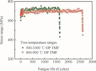
Fig.6 Stress range evolution of DS DZ125 at Δε=0.8%.
3.3.Fractographic and microstructural investigations
Scanning electron microscope and metallographic observations of the fractured specimens were conducted to investigate the failure mechanism.The micromechanism for two different temperature conditions with the same mechanical strain range of 0.8%are demonstrated in Fig.8.The fatigue and fracture zone on the fractography can be clearly differentiated through macroscopic observations.Under high magni fication,no signi ficant fatigue striations were observed for specimens subjected to 500–1000 °C TMF cycles which is shown in Fig.8(a).However,the conditions is different with clear striation for 400–900 °C TMF cycled specimens shown in Fig.8(b).In Kupkovits’study21,the fatigue striations were also not observed for both OP and IP fracture surfaces of DS CM247LC superalloy performed under the temperatures cycling from 500 °C to 950 °C.This may be due to high temperature oxidations,where at lower temperatures,the oxide at the fracture is not so signi ficant within several tens of hours.Additionally,the multiply cracks tended to nucleate at the surface,which determines that it is a surface controlled failure procedure,and the crack initiation mechanism should be focus on the surface regions.

Fig.7 Mechanical strain range versus fatigue life subjected to different TMF and IF cycles.
Fig.9 shows the external cylindrical surfaces of the failed specimens under high magni fications.The arrows indicate the micro-cracks at the oxides.At higher temperature condition of 500–1000 °C,more numerous crack initiation sites were observed,evidence of increased environmentally assisted damage.This is also found in DS GTD-11123which was performed under isothermal conditions comparing the results at 871°C with 982°C.Most of the initiated cracks initiated at oxidized spikes.When the temperature goes from maximum temperature to minimum temperature,the formed oxides experience a brittle–ductile transition temperature.Under OP TMF loadings,tensile stresses are applied on this brittle oxide particles,making it easier form microcrack initiations,then the oxide spikes are formed.Since the chemical compositions of the surface(i.e.Al2O3)and subsurface(i.e.γ′depleted zone)are changed,the microstructures of the superalloy in these areas are weakened and crack initiations are further promoted.As a result of this repeated microrupture process of the oxidation,the cracks are eventually initiated.
An interesting phenomenon is found that the oxidation spikesarelargerunder400–900 °C OP TMF loading(approximately between 10–20 μm)comparing to 500–1000 °C condition(less than 5 μm).It appears that critical size of the oxidation spike exists for each test conditions.At higher temperatures,this critical size is smaller compared to lower temperature conditions.At lower temperature range,environment and fatigue interaction is weaker,leaving more time for the oxides growing.On the other hand,at higher temperatures,cracking in the oxides make the oxygen diffuse into the inner matrix easier.This can be also treated as a result of the cracking mechanism under OP TMF.The cracking in the oxide spikes is controlled by the combination of temperature and mechanical loading.The oxidation and fatigue interaction of this alloy should be carefully considered for the life modeling and its’application in turbine blades.
Additional information on crack initiation could also be obtained by the evaluation of short crack in longitudinal sections of the failed specimens.Metallographic analysis results are represented in Fig.10,which shows the microstructures of the specimens tested under two temperature conditions.The results reveal that the crack density is higher for the higher temperature case corresponding to the previous surface examinations.All of the cracks initiate at the locations with sever oxide spikes.Along the crack path,the oxidation accumulates.However,the depth of the oxide becomes steady approximately 100 μm behind the crack tip.Along the path of the crack excepted for the crack tip,the stresses are 0 MPa,thus it was a pure cyclic oxidation procedure.This pure oxidation process can be supposed by a sub-parabolic growth rule.Since the experiment time was only several tens of hours,i.e.2345 cycles corresponding to 65 h,the thickness of the oxidation is limited by the test time.It should be noted that the oxidation of the free surface along the crack path as well as the crack tip can be more accurately characterized by performing the cyclic oxidation tests.
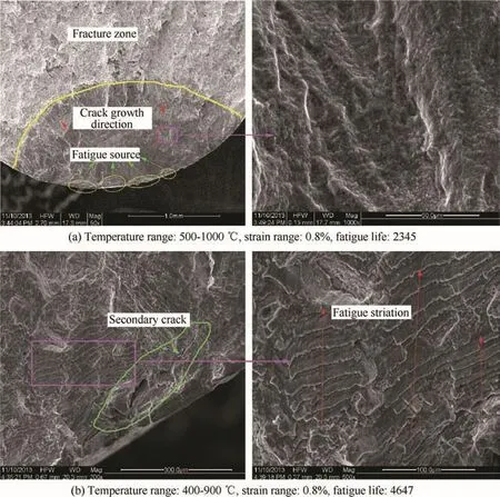
Fig.8 Fracture surface of the failed specimens.
Fig.10(b)also indicates the oxygen diffuses along both the grain boundary and interdendritic areas where the diffusion is easier.The interdendritic areas were weakened by the oxidation process,and then the secondary cracks formed at these regions.Hence,the multiple cracking mechanism at the crack tip is also dominated by environment and fatigue interaction.However,when the cracks are long enough,the cracking will be dominated by the mechanical loading,controlled by the stress intensity factor at the crack tip.In a microscopic scale,the cracking tends to propagate along with the interdendritic areas,which is more perpendicular to the loading direction.
4.Constitutive modeling
For DS and SC superalloys,the macroscopic stress/strain response is anisotropic due to their respective microstructures.Constitutive modeling of these materials considering both anisothermal conditions and material anisotropy is a challenge to the engineering application.Up to now,a variety of constitutive models based on elastic viscoplasticity and crystal plasticity theory have been proposed and developed24–27For the high temperature superalloy application,some sophisticated constitutive models were developed by Manonukul et al.28,Mcke and Bernhardi29,Becker and Hackenberg30and Shenoy et al.6The cyclic plasticity and creep behaviors of high temperature superalloys were well characterized by these contributors.In this section,a modi fied Chaboche’s viscoplastic model is applied to simulate the TMF stress–strain responses of DS DZ125.
4.1.Modi fied Chaboche’s constitutive model
A viscoplastic potential is adopted here using the same form as Chaboche’s model,

where the symbol 〈·〉is Heaviside function,de fined as〈u〉=uifu> 0 and 〈u〉=0 ifu≤ 0.Kandnare temperature dependent material constants. The physical meaning ofKis drag stress.Frefers to yield function,which is expressed as:

The second deviatoric stress tensor invariant,J,is in the form of modi fied von Mises type,which is:

Here,Mijklis a fourth-order tensor considering the yield surface anisotropy,which is used to describe the anisotropic characterization of the DS superalloy.The detailed derivation of M can be referred to our previous work.20Therefore,the modi fied inelastic strain rate is then obtained from Drucker’s normality hypothesis and can be written as the following expression:
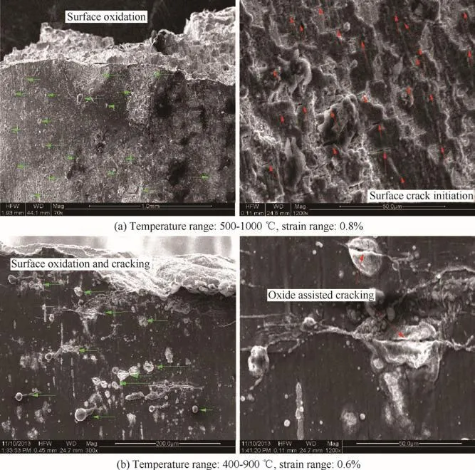
Fig.9 Surface oxidation and crack initiation.
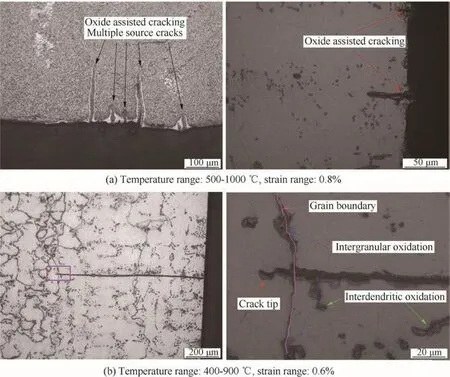
Fig.10 Metallographic observations of cracking initiation from longitudinal section of the failed specimen.
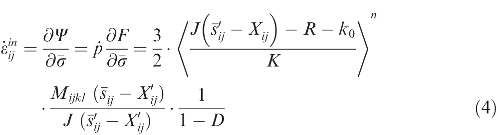
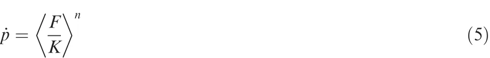
whereRis isotropic hardening.˙pis the accumulated inelastic strain rate,and its expression as:
The Ohno–Wang modi fication is applied in the evolution equation for the back stress describing non-linear kinematic hardening:

where Φ(p)= Φs+(1- Φs)e-ωp. Φsand ω are constitutive parameters.Ck=ckak,ck,ak,β k,mk,rkare all material parameters.˙Tis temperature rate.The first item refers to Prager’s linear hardening.The second item is dynamic recovery which is known as Ohno–Wang modi fication.The third item is describing static recovery.The forth additional item,was first considered by Prager in the context of linear kinematic hardening to consider the temperature rate effect.It was also introduced in the uni fied viscoplastic constitutive equations proposed by Chaboche.31Walker32,Ohno and Wang33also discussed this subject.Ohno and Wang pointed out that the hysteresis loops may shift unreasonably in stress when this temperature rate term is absent in the linear or nearly linear kinematic hardening.
The isotropic hardening evolution equation has the following expression:

whereb,Q,γ andmare material parameters used to describe deformation induced by isotropic hardening.Qris asymptotic value for the yield surface.The first term in Eq.(8)is related to the cyclic hardening or softening phenomenon.The second term describes time dependent recovery effect.If the recovery term is neglect,the isotropic hardening reaches steady state whenRapproaches its asymptotic value.In the present study,the second term is neglected because the cyclic hardening of DZ125 seem to be steady in a few cycles,i.e.20 cycles.The third term,R˙T,suggestedby Benallal and Cheikh34,is added to consider temperature rate effect.Frenz and the co-workers35also veri fied its necessity for the anisothermal conditions.
In order to model the tertiary creep deformation,one effective way is introducing a damage equation into the effective stress.Since only longitudinal orientation is concerned in the present study,for simplicity,an isotropic damage is selected.The Rabotnov–Kachanov law36is approved for the creep damage characterization.20,37Such form of damage characterizing the tertiary creep behavior can be coupled into theeffectivestressin Chaboche’smodel.Theclassical Rabotnov–Kachanov damage evolution is expressed as31:
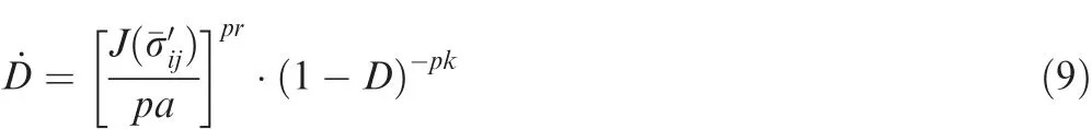
whereσ′
ijis deviatoric components of effective stress,J(σ′
ij)refers to the second invariant of the effective stress.pa,prandpkare three material parameters determined by the experimental creep deformation curves.
To sum up,there are a total of 28 material parameters in the modi fied Chaboche model.In order to determine the parameters,isothermal tensile,fatigue and creep tests are necessary.Since one purpose of the present research is to predict TMF stress and strain responses, five groups of temperaturedependent parameters,i.e.20,650,760,850,980°C,were determinedthrough a Levenberg–Marquadt optimization algorithm.The detailed parameter optimization procedure were carried out according to the following three steps:
(1)Using monotonic stress and strain test results,M11,M33andM55,K,n,k0,a1,a2,c1andc2,are identi fied to characterize the inelastic behavior of the material.In this step,test results in longitudinal and transverse orientations should be included.Additionally,in both of orientations,at least two curves at different loading rates should also be contained.
(2)Using creep strain curves,r1,r2,β1,β2,pa,prandpkare identi fied to characterize both of steady and tertiary stage creep deformation.In this step,at least one creep curve should be included at each temperature.Since creep is mainly occurred at high temperatures,creep dependent parameters were obtained at 760,850 and 980°C.
(3)m1,m2,Φs,ω are optimized using the isothermal fatigue tests atRε=-1.Then,bandQare optimized using the isothermal fatigue tests atRε=0.
4.2.Simulations under isothermal fatigue and creep loadings
In order to simulate the stress/strain responses under different loading conditions,the modi fied Chaboche’s model is implemented as an ABAQUS user material(UMAT)subroutine.The isothermal monotonic,isothermal fatigue and creep response simulations at 850 °C are demonstrated in Figs.11–14.As it can be seen in Figs.11 and 12,the rate dependence in the longitudinal orientation is characterized by Chaboche’s constitutive model.Due to the induction of anisotropic material tensor,stress and strain responses in longitudinal and transverse orientations are both wellsimulated, thus materialanisotropy is wellmodeled by the modi fied Chaboche’s model.Cyclic viscoplastic simulations are demonstrated in Fig.13.The results reveal that the anisotropy hardening is poor characterized.The main reason is that there was no anisotropy modi fication in isotropic hardening term in Eq.(8).

Fig.11 Experimental and simulated uniaxial tensile stress/strain responses of DZ125 superalloy in longitudinal(L)and transverse(T)orientations at 850°C.
In order to predict tertiary creep behavior of the materials,the parameters(i.e.pa,prandpk)which are related to creep damage should be determined.In the present,the creep deformation curves under 430 MPa and 520 MPa were used.The simulations and predictions were demonstrated in Fig.14.It is appreciated that the present constitutive model can predicted creep curves at 511,480,460 MPa very well.However,as the Kachanov damage is coupled,the model is extended to obtain the ability of modeling the tertiary creep deformation.This is especially important at the higher temperature under relative low stress where the tertiary creep mechanism dominates the failure.
4.3.Predictions under TMF loadings
The predicted and experimental OP TMF hysteresis loop of DZ125 is presented in Fig.15.Since the material data at different temperatures is gained from the baseline isothermal tests,a Calmat subroutine is employed to linearly interpolate the model parameters at the non-experimental temperatures.The stress asymmetry is well modeled.However,there are some errors at high temperature half cycles.There are three main reasons.Firstly,due to the absence of isothermal test at 1000°C,maximum temperature of the baseline isothermal tests is 980 °C,which is 20 °C lower than the upper temperature of the predicted cycle,so the parameter extrapolation will bring in some errors.Secondly,limited by the controlled temperature rate of the test setup,i.e.10°C/s,the TMF test was performed at the relative low strain rate(i.e.2×10-4s-1when the strain range was 0.01),which was not covered by the isothermal baseline test conditions.This maybe another factor in fluencing the accuracy.Additionally,because the temperature accuracy of the TMF tests was only controlled within 10°C,the measured stress and strain responses may have errors.It should be noted that since TMF test data were not used for the parameter fitting,this agreeable simulation can be a result of the strong predictable ability of Chaboche’s viscoplastic model.
5.TMF life prediction
The damage of fatigue failures under complex cyclic loadings at high temperature always exists as a combination of fatigue,creep and environment damage.It is a feasible way to separate damage involved from complex loadings into several simple damages such as fatigue,creep and environment damage.And the total damage will be summarized by linear accumulation of each of the simple damages,which can be written in the following expression3,

Here,Dtotal,Dfatigue,DcreepandDenvare total damage and damage due to fatigue,creep and oxidation,respectively.According to linear cumulative assumption,the fatigue damage can be expressed as the reciprocal of fatigue life:

Here,Nfatigueis pure fatigue life which is based on a strain–life relationship:

wherecanddare pre-factor and exponential term.It should be noted that these two parameter must be fit to lower temperature fatigue data where creep effect as well as oxidation effect are negligible.In the present study,760°C isothermal fatigue data were chosen.The fitted results are described in Fig.16.

Fig.12 Stress/strain response in the longitudinal and transverse direction under fatigue loadings at 850°C with strain ratio R=-1.

Fig.13 Experimental and simulated stress ranges versus cycles under strain range of 1.6%(R=-1,850°C).
Since only OP TMF is discussed,the creep damage could be neglected as the tensile stresses always cycle at lower temperatures typically below 750 °C.According to Neu–Sehitoglu model,the oxidation damage is expressed as3,
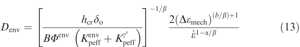
where Δεmechandε˙ are mechanical strain range and mechanical strain rate,respectively.hcris a critical length where oxidation attack trails behind crack growth.δois a measurement of oxide plusdepleted zone ductility.Bis a material coef ficient.band β is the time related mechanical strain range exponent.α represents the thermal strain rate sensitivity exponent.are effective parabolic constants for oxidation and γ′depletion,respectively.Φenvis phasing factor which can be written as,


Fig.14 Experimental and simulated creep strain in longitudinal direction of DZ125 DS superalloy at 850°C.
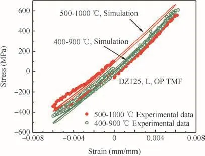
Fig.15 Stress–strain response for DZ125 DS superalloy under 400–900 °C and 500–1000 °C OP TMF.
where φenvis de fined as a function of the ratio of thermal and mechanical strain rates,

Here εthis thermal strain and ξoxis material constants.The oxidation and γ′depletion terms in the environment damage equation are de fined as,

The termsDoxandQoxare oxidation diffusion coef ficient and activation energy,whileDγ′andQγ′are γ′diffusion coef ficient and activation energy,respectively.Since the parametershcr,δo,and β in Eq.(13)are constants,an effective parameterBeffcan be de fined as:


Fig.16 Isothermal fatigue life modeling at 760°C.

Table 1 Environment damage constants.4
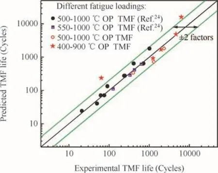
Fig.17 Comparison between predicted and test lives under different TMF loadings.
Hence,Eq.(13)is rewritten as:

Excepted forBeffandb,the environmental constants used for DZ125 are those fitted to the superalloy Mar-M247.4Beffandbare fitted using 500–1000 °C OP TMF test results of DZ125 which are performed in the present research.All of the constants are listed in Table 1.
The predictions are demonstrated in Fig.17.Three different temperature ranges are considered from present study and literature.The results reveal that most of the lives are predicted by a factor of 2.Since the dominated damage is oxidation,the Neu–Sehitoglu law has a reasonable characterization for OP TMF damage.Though it was first introduced from a steel,the similar micro-rupture procedure made it suitable for Nickel base superalloy after some modi fication on the oxidation damage parameters.
6.Conclusions
Thermal mechanical fatigue of a DS superalloy was experimentally studied.The results reveal that the cyclic stresses are asymmetric due to the temperature dependent modulus and yield property at strain ratio of-1.The responses at the high temperature half-cycle were affected by the temperature more signi ficantly than the low temperature half-cycle.The fatigue life results indicated that maximum and minimum temperature drop have very strongly reduced knockdown effect on fatigue lives.As the maximum and minimum temperature of the TMF cycles raised 100°C,fatigue life is shortened nearly by a factor of 2–3.Microstructure observations of the failed specimens showed that higher temperature suffered more oxidation damage with multiple crack initiations at the surfaces.Almost all of the cracks initiated at the oxidation spikes.More numerous crack initiation sites were observed under 500–1000 °C TMF loading than that of 400–900 °C condition.The difference of the TMF life results and critical size of the oxidation spikes at two temperature ranges indicated that the oxidation and fatigue interaction under higher temperatures is much easier to occur.Fatigue crack growth path tended to grow along the interdendritic areas.When the crack tip encounters the dendrite arms,the oxygen diffuses along both of the directions.The crack will propagate along two directions,but only one crack can propagate to form the main crack,and it trended to propagate along the direction near the transverse orientation of the specimen.
A modi fied Chaboche’s constitutive model is developed to capture the stress–strain response in the longitudinal and transverse orientations.Rate dependent plasticity,material anisotropy and anisothermal affects are all captured.The temperature effect on the TMF cycles is well modeled.Since most of the simulations and predictions are reasonable,this model is a useful way for the component level analysis considering complex loading histories.
Finally,the TMF life modeling of DZ125 is realized using a Neu–Sehitoglu damage equation.Though one group of test data(i.e.500–1000 °C OP TMF)were used to fit the material constants,both of 400–900 °C and 550–1000 °C OP TMF are reasonably predicted.
Acknowledgment
This research was financially supported by the National Basic Research Program of China(No.2015CB057400).
1.Lasalmonie A,Pellerin F,Fournder,D.Thermomechanical fatigue in gas turbine engines:the reason of a concern.Proceedings of the 81th AGARD structures and materials panel;1995 Oct 2–4;Banff,Canada:North Atlantic Treaty Organization.AGARDCP-569;1996.p.1.1–1.5.
2.Neu RW,Sehitoglu H.Thermomechanical fatigue,oxidation,and creep:Part I damage mechanisms.Metall Trans A1989;20(9):1755–67.
3.Neu RW,Sehitoglu H.Thermomechanical fatigue,oxidation,and creep:Part II life prediction.Metall Trans A1989;20(9):1769–83.
4.Sehitoglu H,Boismier DA.Thermo-mechanical fatigue of Mar-M247:Part 2-life prediction.J Eng Mater Technol1990;112(1):80–9.
5.Beck T,Pitz G,Lank KH,Lo¨he D.Thermal–mechanical and isothermal fatigue of IN 792 CC.Mater Sci Eng A1997;234–236:719–22.
6.Shenoy M,Mcdowell D,Neu RW.Transversely isotropic viscoplasticity model for a directionally solidi fied Ni-base superalloy.Int J Plast2006;22(12):2301–26.
7.Kupkovits RA,Neu RW.Thermomechanical fatigue of a directionally-solidi fied Ni-base superalloy:smooth and cylindricallynotched specimens.Int J Fatigue2010;32(8):1330–42.
8.Kupkovits RA,Neu RW.Thermomechanical fatigue of a directionally-solidi fied Ni-base superalloy in the presence of stress concentrations.Proceedings of the ASME turbo expo 2009:power for land,sea,and air,2009 June 8–12;Florida,USA.Orlando:ASME;2009.p.163–73.
9.Zamrik SY,Renauld ML.Thermo-mechanical out-of-phase fatigue life of overlay coated IN-738LC gas turbine material.ASTM Special Technical Publication2000;1371:119–37.
10.Bernstein HL,Grant TS,Mcclung RC,Allen JM.Prediction of thermal-mechanical fatigue life for gas turbine blades in electric power generation.ASTM Special Technical Publication1993;1186:213–38.
11.Lee D,Shini I,Kim Y,Koo JM,Seok CS.A study on thermo mechanical fatigue life prediction of Ni-base superalloy.Int J Fatigue2014;62:62–6.
12.Vose F,Becker M,Fischersworring-Bunk A,Hackenberg HP.An approach to life prediction for a nickel-base superalloy under isothermal and thermo-mechanical loading conditions.Int J Fatigue2013;53:49–57.
13.Wang RQ,Jing FL,Hu DY.In-phase thermal–mechanical fatigue investigation on hollow single crystal turbine blades.Chin J Aeronaut2013;26(6):1409–14.
14.Bressers J,Timm J,Williams J,Bennett A,Affeldt E.Effects of cycle type and coating on the TMF lives of a single crystal nickel based gas turbine blade alloy.ASTM Special Technical Publication1996;1263:56–67.
15.Chataigner E,Remy L.Thermomechanical fatigue behaviour of coated and bare nickel-based superalloy single crystals.ASTM Special Technical Publication1996:1263:3–26.
16.Bressers J,Martinez-Esnaola JM,Martin-Meizoso A,Timm J,Arana-Antelo M.Coating effects on crack growth in a single crystal nickel based alloy during thermo-mechanical fatigue.ASTM Special Technical Publication1996;1263:82–95.
17.Bauf fld B,Tzimas E,Mllejans H,Peteves S,Bressers J,Stamm W.Thermal–mechanical fatigue of MAR-M509 with a thermal barrier coating.Mater Sci Eng A2001;315(1–2):231–9.
18.Amaro R,Antolovich S,Neu RW.Mechanism-based life model for out-of-phase thermomechanical fatigue in single crystal Nibase superalloys.Fatigue Fract Eng Mater Struct2012;35(7):658–71.
19.Fernandez-Zelaia P,Neu R.In fluence of notch severity on thermomechanical fatigue life of a directionally solidi fied Ni-base superalloy.Fatigue Fract Eng Mater Struct2014;37(8):854–65.
20.Shi DQ,Dong CL,Yang XG.Constitutive modeling and failure mechanisms of anisotropic tensile and creep behaviors of nickelbase directionally solidi fied superalloy.Mater Des2013;45:663–73.
21.Kupkovits RA.Thermomechanical fatigue behavior of the directionally-solidi fied nickel-base superalloy CM247LC[dissertation].Atlanta:Georgia Institute of Technology;2009.
22.Yu HC,Wu X.Aero engine materials handbook.4th ed.Beijing:Aviation Industry Press;2010.p.25–44.
23.Gordon AP.Crack initiation modeling of a directionally-solidi fied nickel-base superalloy[dissertation].Atlanta:Georgia Institute of Technology;2006.
24.Chaboche JL.Constitutive equations for cyclic plasticity and cyclic viscoplasticity.Int J Plast1989;5(3):247–302.
25.Chaboche JL.A review of some plasticity and viscoplasticity constitutive theories.Int J Plast2008;24(10):1642–93.
26.Roters F,Eisenlohr P,Hantcherli L,Tjahjanto DD,Bieler TR,Raabe D.Overview of constitutive laws,kinematics,homogenization and multiscale methods in crystal plasticity finite-element modeling:theory,experiments,applications.Acta Mater2010;58(4):1152–211.
27.Chaboche JL,Gaubert A,Kanout P,Longuet A,Azzouz F,Mazie`re M.Viscoplastic constitutive equations of combustion chamber materials including cyclic hardening and dynamic strain aging.Int J Plast2013;46:1–22.
28.Manonukul A,Dunne F,Knowles D,Williams S.Multiaxial creep and cyclic plasticity in nickel-base superalloy C263.Int J Plast2005;21(1):1–20.
29.Mcke R,Bernhardi OE.On temperature rate terms for viscoplastic constitutive modelswith applicationsto high temperature materials.ComputMethodsApplMechEng2006;195(19):2411–31.
30.Becker M,Hackenberg HP.A constitutive model for rate dependentand rateindependentinelasticity:application to IN718.Int J Plast2011;27(4):596–619.
31.Chaboche JL.Viscoplastic constitutive equations for the description of cyclic and anisotropic behavior of metals.Bull Acad Polonaise Sci Ser Sci Tech1977;25(1):33–42.
32.Walker KP.Research and development program for non-linear structural modeling with advanced time temperature dependent constitutive relationships.Report No.:PWA-5700-50,NASA CR-165533;1981.
33.Ohno N,Wang J.Transformation of a nonlinear kinematic hardening rule to a multisurface form under isothermal and nonisothermal conditions.Int J Plast1991;7(8):879–91.
34.Benallal A,Cheikh AB.Constitutive laws for engineering materials.New York:ASME Press;1987.p.145–56.
35.Frenz H,Meersmann J,Ziebs J,Ku¨hn HJ,Sievert R,Olschewski J.High-temperature behaviour of IN 738 LC under isothermal and thermo-mechanical cyclic loading.Mater Sci Eng A1997;230(1):49–57.
36.Chaboche JL.Constitutive equations for cyclic plasticity and cyclic viscoplasticity.Int J Plast1989;5(3):247–302.
37.Kachanov M.Elastic solids with many cracks and related problems.Adv Appl Mech1993;30:259–445.
杂志排行

CHINESE JOURNAL OF AERONAUTICS的其它文章
- Plastic wrinkling prediction in thin-walled part forming process:A review
- Progress of continuously rotating detonation engines
- Microstructure control techniques in primary hot working of titanium alloy bars:A review
- A hybrid original approach for prediction of the aerodynamic coefficients of an ATR-42 scaled wing model
- Dynamic modeling and analysis of vortex filament motion using a novel curve- fitting method
- Boundary-layer transition prediction using a simpli fied correlation-based model