A new method of single celestial-body sun positioning based on theory of mechanisms
2016-11-21ZhangWeiXuXiaofengWuYuanzhe
Zhang Wei,Xu Xiaofeng,Wu Yuanzhe
aAirport College,Civil Aviation University of China,Tianjin 300300,China
bAviation Ground Special Equipment Research Base,Tianjin 300300,China
cAeronautical Automation College,Civil Aviation University of China,Tianjin 300300,China
dAeronautical Engineering College,Civil Aviation University of China,Tianjin 300300,China
1.Introduction
Despite a widespread application of global navigation satellite systems(GNSS),celestial positioning has still held an important position no matter as an independent navigation method or as a part of an integrated navigation system.1–4It is well accepted that celestial navigation is capable of full autonomy and strong anti-interference.To both military aviation and civil aviation,autonomy and anti-interference are important to a navigation system.According to recommendation of next-generation navigation,performance based navigation(PBN)has been proposed by the International Civil Aviation Organization(ICAO).PBN demands an autonomous navigation,including:the warning precision,which is de fined as integrity monitoring alert limit(IMAL),is 0.3 n miles at approach phase,2.0 n miles in air route and 1.0 n miles in terminal area.5With this precision,celestial navigation system is a suitable solution or a backup at least.
Among many celestial navigation methods,sun positioning is known as the oldest single celestial-body navigation method.It is also regarded as an important foundation of other methods.As a kind of celestial navigation technology,sun positioning is a reliable way to obtain latitudes and longitudes of observation points.And,it is only based on single star’s position and orientation information,such as Polaris and solar vectors.It is mainly used to calculate the longitude and latitude coordinates of observation place by the sun direction in earth surface coordinate,including azimuth angle and elevation angle.6In recent years,primary research results of single celestial positioning are as follows.Wang et al.7reached the conclusion that the position lines of azimuth difference and height difference can be used for the single celestial positioning.Tang and Yang8obtained their position information with a single celestial altitude and azimuth information,which overcomes defects of long period and low precision in sun sight running fixing.Jiang and Yin9put forward a new method to render the dynamic scene to simulate celestial fixing principle of sextant in navigation and presented a mathematical model of celestial fixing by sextant.It improved that single celestial navigation is an automatic process.Jia et al.10realized sun sight running fixing with computer-aided calculating transcendentalequation and accuracycompensation theory.Its method can save time and improve the positioning betimes greatly.Based on sun’s azimuth angle and elevation angle,Yuan and Zhang11designed a positioning system to achieve a semi-automatic single celestial positioning.Wang et al.12analyzed relationship between polarization distribution of skylight and sun orientations and put forward a new mode of celestial navigation based on measuring skylight polarization at two mutually perpendicular orientations.Peng et al.13built an automatic calculation system of navigation astronomical orientation by C sharp tool and altitude difference principle,which improved speed and precision of calculation.
It can be seen that many studies focused on improving detection instruments’precision and exploring new technologies,such as the high-precision charge-coupled device(CCD)star sensors and the integrated navigation systems.2,3Few studies centered on principle and algorithm of single celestial positioning.Besides,there are problems in current single celestial positioning algorithms.For one thing,we always derive and calculate position information depending on traditional celestial coordinates,which need apparent motion of planets,spherical triangle,and some experience-based error corrections.6,8For another,a certain principle error happens because of curves replaced by straight lines in process of height difference calculation.14Moreover,if we consider formula errors in single celestial navigation process,positioning error in general moments is far more than the error in transit moment.The ‘transit moment limitation”in traditional calculation results in discontinuous navigation information,6,15so the real time positioning can be implemented in this way.
To solve problems among the existing single celestial positioning method,calculation framework of solar positioning is reconstructed by theory of mechanisms.Wang16and many researchers testi fied the dependence of solar vectors on coordinates and time of observation point.Authors have introduced a proven C1R2P2mechanism,whose forward kinematics can be used for calculation of solar vector.In an inverse way,latitude and longitude expressions of observation point in the Greenwich mean time(GMT)can be derived by inverse kinematics of mechanisms17,18with a given solar vector.In a word,if time information(year,month,date,hour,minute and second)and its corresponding solar vector in an observation point are known,latitude and longitude of this point are solvable.
Since every variable is related to an explicit joint motion de fined by theory of mechanisms,the proposed calculation method is likely to be more comprehendible.Based on those achieved joint motions,a positioning solution is mathematically easy to get by solar vectors.A new method is raised to break through traditional celestial coordinate calculation with astronomical trigonometry,overcome the limitations of sun sight running fixing(obtaining observation’s position by observing sun’s position at two different moments),achieve continuous positioning at a long time,and improve practicability of single celestial-body positioning applications.In addition,this method utilizes only GMT instead of local time in calculation of latitude and longitude.So it can remove the timing error in radio time service process and improve the positioning precision.To reduce the error of the proposed method,it can be used to combine with inertial navigation equipment and random weighting estimation method.19
2.A sun positioning algorithm based on theory of mechanisms
A new calculation model of sun positioning can be constructed with a serial mechanism C1R2P2,as shown in Fig.1.We use five kinematic joints of C1R2P2mechanism to simulate the revolution and rotation of earth to the sun.The rotation joint θ1stands for the revolution of earth around sun in the ecliptic plane.The prismatic jointd2stands for radius change of earth revolution,corresponding to the elliptical orbit.The rotation joint θ3stands for reversing rotation corresponding to revolution angle,in order to maintain constant direction of the axis of earth(θ3=-θ1).The cylindrical joint can be divided into a prismatic jointd4and a rotation joint θ5,stands for a rotation sleeve along polar axis of the earth.The prismatic jointd6stands for radius change on latitude circle of the earth.The joint variablesd4,θ5andd6are used together to simulate an arbitrary site on earth’s surface.d7has a very tiny value to permit free moving of jointd4along the polar axis.The coordinateoxyzis the earth surface coordinate,in which,xstands for positive west,ypositive south,andzzenith.According to authors’previous study,solar vector expressions S inoxyzcoordinate can be achieved by product of exponentials formula method20or Denavit-Hartenberg method21in the form of
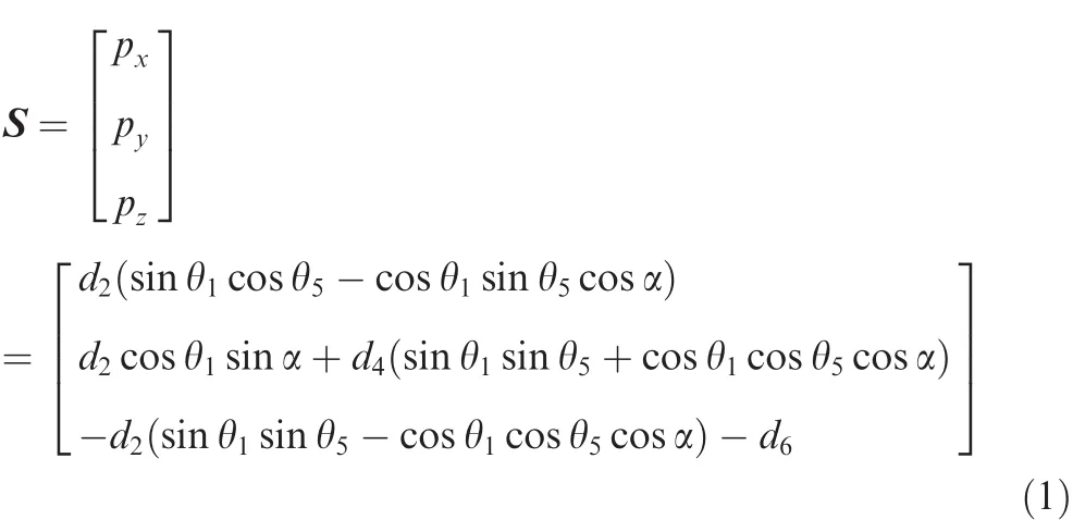
wherepx,pyandpzare the projections of solar vector in directionsx,yandzrespectively in the coordinate systemoxyz.α =23°26′is the angle between ecliptic plane and equatorial plane.θ1can be calculated by summing up the number of days(N)away from the date of perihelion and calculating the relationship expression between θ1andN.Because sun-earth distanced2is much greater than distanced6,d6is then ignored.Further Eq.(1),one has
where the variable ψ represents the latitude.
2.1.Calculation of latitude
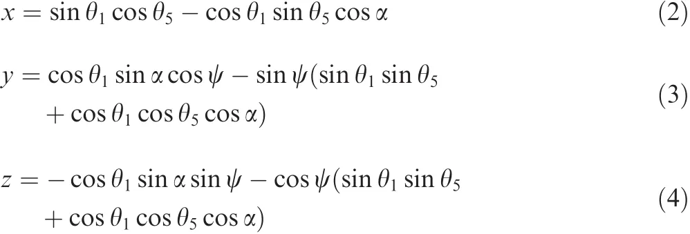
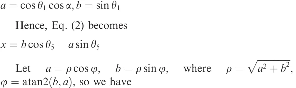
To achieve latitude from Eqs.(2)–(4),Euler transform solution and double variables arc tangent function22are applied to calculation.The detailed calculation process is as follows.
Firstly,de fine

2.2.Calculation of longitude
Longitude of observation point is related to time.TimeTherein is used as GMTTgfor calculation.The calculation of longitude can be divided into three steps:(1)observation position is firstly assumed as a Greenwich area.Hypothetical longitude θ5gcan be calculated by formula of angle between line and plane in space as shown in Fig.2;(2)according to a known solar vector(direction of sunlight at this moment),the actual θ5can be calculated by Eq.(5);(3)considering difference between hypothetical θ5gand actual θ5,time difference between Greenwich area and actual observation area is applied to achieve a true longitude.
The detailed calculation of hypothetical θ5gis shown as follows.
As shown in Fig.2,angle β between lineBCand planeABDcan be worked out by
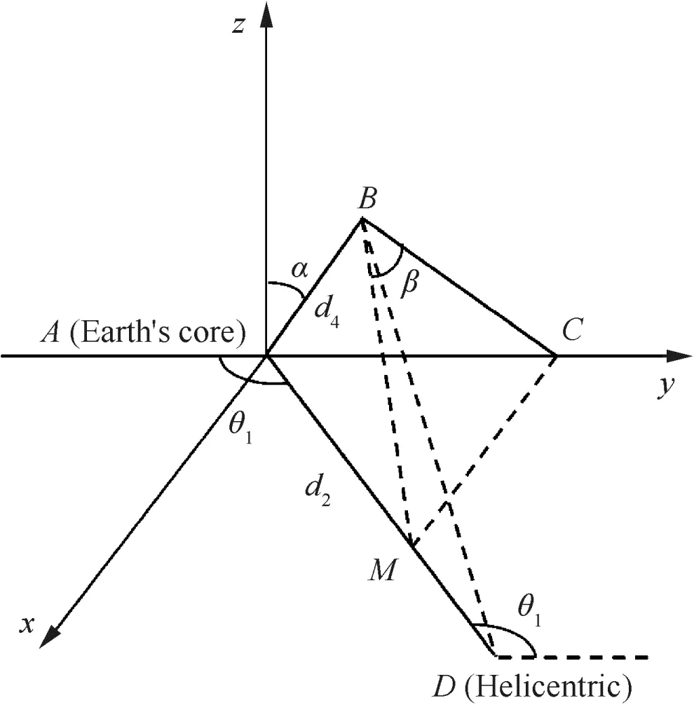
Fig.2 Angle relation diagram of line and plane for longitude calculation.

3.Theoretical veri fication and comparative analysis
A comparative analysis is made in this section,in which,Michalsky’s and Wang’s formulas are chosen as known solar vectors’basis in the following examples.In detail,latitude calculation formulas were derived from Michalsky’s sun azimuth and elevation angle formulas23and Wang and Liu’s solar declination formulas.24The longitude calculation is calculated based on the time difference by the radio time.This contrastive algorithm is used as a standard reference and its errors of longitude and latitude are set to be zero.
The solar vector calculation parameters by the astronomy formulas are found from public resources.The solar vector calculation is generally based on the sun azimuthAand elevation angleH,as

where ω is the solar hour angle in local time,it equals 0°at noon,is negative in the morning and positive in the afternoon,and δ is the solar declination whose value is put forward by Wang and Liu24as
where INT represents the integer-valued function.Besides that,sun azimuthAand elevation angleHalso need to be made an indirect projection in the coordinate system,and the true solar vector expression can be given as

This expression is selected to calculate known solar vectors.The time is as GMT and the revolution angle θ1can be obtained from relational expression with the number of daysNaway from the date of perihelion.
Considering symmetries of the earth as a globe and multiple roots of trigonometric functions,there exist multiple solutions in positioning calculation with a known solar vector.There would have more if the earth is assumed to be transparent to receive sunlight no matter in nighttime or daytime.Thus,an elimination of multiple solutions is needed to reach the expected one.This elimination has four phases.Firstly,latitude and longitude of a solution need to be transformed into standard value interval[-180°,180°].Periodical solutions are removed to avoid repeated roots due to trigonometric functions.Secondly,latitude coordinates out of value interval[-90°,90°]have to be eliminated as de finition in geography.It is noticed that those eliminated latitude coordinates cannot be further transformed into[-90°,90°]since sine and cosine function are used simultaneously.Thirdly,a rough judgment of local time,such as day or night,morning or afternoon,can help to locate an actual local time calculated from two possible longitude coordinates.It is easy to do this through observing sun direction in local coordinate system(see if the sun is closer to east than to west or not).Finally,the left longitude coordinate related to the right local time is achieved.This longitude coordinate and the corresponding latitude coordinate are grouped to be the only solution depending on the given solar vector.
Note:the same sign in three examples is unrelated and data is independent;eliminated unit is(°).
3.1.Example 1
Comparative data:Tianjin,
Known data:
GMT:April 5,2014,7:12 a.m.
Revolution angle:θ1=105°,calculated by computer.
Solar vector is obtained from the astronomy Eqs.(9)–(12)and calculated by computer with local time,longitude and latitude,and the results are as follows:

3.1.1.Calculation of latitude and longitude

In the above expression,the subscript is only to distinguish the difference between the calculated data.In θ51and θ52,51 stands for the first group and 52 stands for the second group.In ψ11and ψ12,11 stands for the first data in the first group data and 12 stands for the second data in the first group data.The following de finitions are the same.According to the latitude’interval[-90°,90°],we can eliminate unreasonable data and get
According to longitude solutions in Eq.(15)and the known GMT,the local time can be worked out and the answer isT1=21:00 andT2=15:00.Since sunlight cannot be seen at night 21:00(it is not the calculating time we set in this case,but it may be a calculating time in other cases),some multiple solutions can be eliminated.Then the unique longitude coordinate can be obtained as γ2=116.993748°E.Based on this achieved longitude coordinate and Eq.(14),the unique latitude coordinate is located as ψ22=39.001987°N.The latitude and longitude coordinate are then shown as
3.1.2.Error calculation
Making a difference between calculated latitude and longitude solution Eq.(16)and actual comparative data,we have

3.2.Example 2
Comparative data:London,

Known data:
GMT:March 21,2014,9:00 a.m.
Revolution angle:θ1=90°
Solar vector:

which is obtained from the astronomy formulas and calculated by computer.
3.2.1.Calculation of latitude and longitude
At first,the known data are applied to Eqs.(5)and(6),which gives
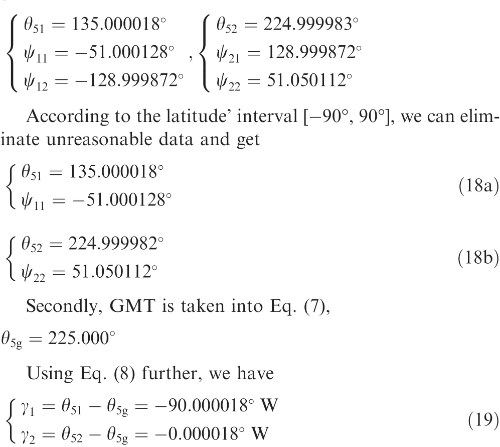
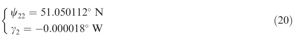
According to longitude solutions in Eq.(19)and the GMT,the local time can be calculated asT1=3:00 andT2=9:00.Since a day time but a night time is selected,some multiple solutions can be eliminated.Then the unique longitude solution can be obtained as γ2=-0.000018°W.Based on longitude result and Eq.(18),the left latitude solution is,ψ22=51.050112°N.The latitude and longitude coordinate is then
3.2.2.Error calculation
Making a difference between calculated latitude and longitude data Eq.(20)and actual comparative data,we can get

3.3.Example 3
Comparative data:New York,
Known data:
GMT:December 22,2013,16:56 p.m.
Revolution angle:θ1=0°
Solar vector:

which is obtained from the astronomy formulas and calculated by computer.
3.3.1.Calculation of latitude and longitude
At first,known data are applied to Eqs.(5)and(6)gives

According to the latitude’interval[-90°,90°],we can eliminate unreasonable data and get
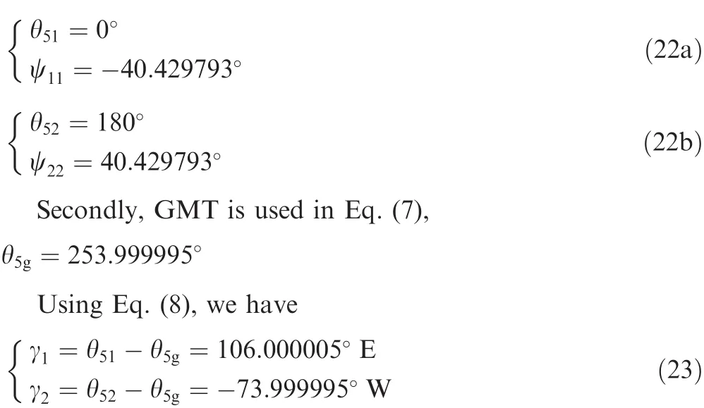
According to the longitude in Eq.(23)and the GMT,the local time can be calculated,T1=24:00 andT2=12:00.Since a day time is chosen,some multiple solutions can be eliminated.Then the unique longitude coordinate can be obtained as γ2=-73.999995°W.Based on longitude result and Eq.(22),solutions of latitude can be eliminated and the unique latitude coordinate is achieved,ψ22=40.429793°N.The latitude and longitude coordinates are shown as follows:
3.3.2.Error calculation
Making a difference between calculated latitude and longitude data Eq.(24)and actual comparative data,we can get

4.A test via a designed iOS application
Smart mobile device leads the trend of modern life.It becomes an important tool platform to supply many services.In order to test the feasibility of the proposed positioning theory and build a base of special instrument,a smart phone positioning application is developed and introduced in this section.The development platform is based on Apple’s iOS system.
4.1.Realization principle
Current smart phones,like iPhone,are equipped with many useful sensors.For example,gyroscope(Gyro)and magnetic sensor can be used to provide phone’s attitude in the space,which can be used by the proposed algorithm as an input data for positioning.Also,a mini global position system(GPS)receiver has been embedded into a smart phone,by which,the WGS84 coordinates of device’s position can be shown on the screen in real time.Hence,GPS data should be a good comparative object to the output of the developed application based on the proposed algorithm.Besides,a phone camera can help to find the sun.Thus,all basic parameters including solar altitude,geomagnetic azimuth and GMT can be acquired by an iPhone for the proposed method.
Values of solar zenith angle,azimuth angle and geomagnetic azimuth angle are achieved and calculated firstly.According to the de finition of iPhone’s space coordinates,the attitude information of the phone in the space can be obtained by those angles.The axis of acceleration sensors and Gyro are shown in Figs.3 and 4 respectively,which can be found in Alan’s book.25

Fig.3 Axis of acceleration sensors.

Fig.4 Three-axis digital Gyro setting in the Phone.
A phone’s camera actually consists of optic sensors which can be used to determine the relative direction of the sun about the phone’s screen.Based on optic principle,Fis the intersection of camera imaging when the sun’s rays are perpendicular to the camera(see Fig.5).When the sun is located in field of view of phone’s back camera,elevation angle can be determined.At the same time,the geomagnetic direction angle of sun can be calculated with space vector algebra.Since GMT of a smart phone is now accurately supplied by time service center,positioning time isrecorded by the developed application.
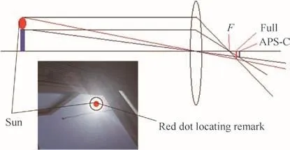
Fig.5 Camera positioning principle.
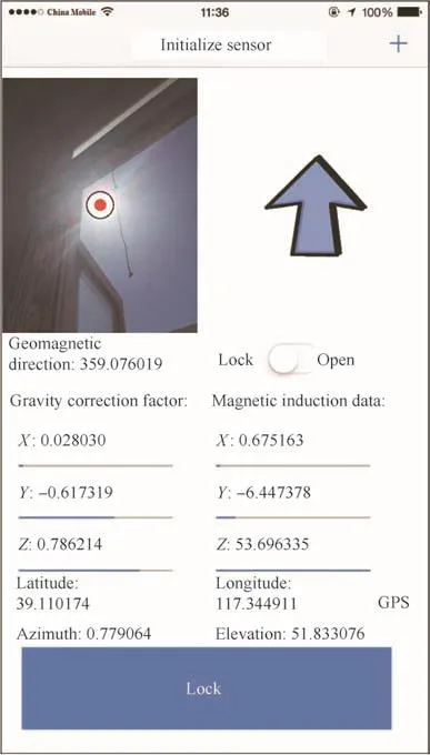
Fig.6 Positioning application interface.
Through the above steps,three input parameters are obtaind for the proposed algorithm.These manipulations and the proposed algorithm are integrated to developed phone’s application.So,latitude and longitude coordinates can be obtained from this celestial body positioning method.As it can be seen in Fig.5,a red dot is designed to locate position of sun in the field of view.As shown in Fig.6,by opening the application switch,lay the sun into red dot on the phone’s screen and press LOCK button,positioning calculation is completed and shown on the screen.All the units of the angles in the figures are(°).
4.2.Data processing and deviation
In order to obtain more accurate spatial attitude data and correcte accelerometer bias caused by hand jitter in measurement,a method for the mutual correction of the gyroscope and accelerometer is used to obtain accurate gravity direction data,which makes the calculation more accurate in developed application.As shown in Fig.7,GPS data of the same position is also displayed in the result screen as a comparative object.
5.Discussions and conclusions
According to positioning methodology in Section 2,theoretical comparison in Section 3,and practical test in Section 4,the following discussions and conclusions can be drawn:
First of all,the calculation errors of latitude and longitude are about a few thousandths in angle.Considering the ignored tiny valued6/d2in this model,error of astronomy formula and the effective digital selection in the process of calculation,error results are considered to be reasonable.That is to say,the presented expressions of latitude and longitude by theory of mechanisms are correct and applicable.As it can be seen,performance of the proposed algorithm is essentially equivalent to the contrastive algorithm.Besides,the proposed method breaks up the fixed thinking mode of calculating celestial coordinates with astronomical trigonometry and simpli fies the complexity of parameters calculation.Especially,the method only makes use of GMT and solar vector of observation area.
To its accuracy,by calculating arc-length of the earth circle,L=Δ×π×r/180(Δ is result error of latitude and longitude;ris radius of the earth),theoretical distance error of the proposed positioning method can be calculated with error results Eqs.(17),(21)and(25).It shows that the maximum distance error is about 0.7 km,approximately equals 0.4 n mile.At this level,it is equivalent to former articles and can be acceptable by PBN requirements.Besides,the precision of the proposed method can be further reduced by high-precision observation instruments or combined with an inertia navigation system.Hence,the proposed method meets the basic requirements of navigation application in civil aviation.
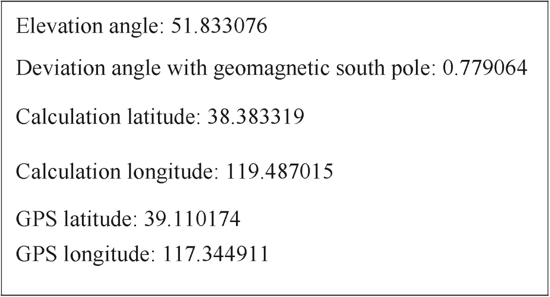
Fig.7 Interface of positioning results and comparative GPS data.
To test its practicality and robustness,a phone application is developed and utilized.The positioning application that originated from the proposed algorithm is tested by hundred times.According to one of these tests,as it shown in Fig.7,position coordinates are obtained by the proposed method and compared to GPS data in the same position at the same time.It shows a certain deviation in calculated coordinates to GPS data,but within a certain range.Hence,the proposed positioning method is applicable and stable.It needs to be gradually modi fied though.There are reasons for deviation in current application,such as:measurement error of phone’s sensors,our simple but rough way to locate sun’s direction,earth’s geomagnetic variety change,the atmospheric refraction of sun’s rays(deviation of morning and evening is more obvious),deviation of WGS84 coordinates and Chinese GCJ02 coordinates(normally about 300–500 m),etc.To improve the accuracy of this application in an effective way,a bias data in every usage should be recorded and uploaded to a cloud database and get revised for the next use if it can be used by a large number of customers in different locations.Or,a special instrument that originates from proposed method is looked forwards in the future.
Finally,the proposed algorithm can be applied to the calculation of local time,latitude and longitude.In this way,positioning time can be saved greatly and the long-period’s problem in sun sight running fixing process can be solved.Even during the daytime,a continuous positioning can be realized.It is believed that single celestial sun positioning will have a better application prospect.Its methodology of using theory of mechanisms can inspire development of new sun positioning device in both application and hardware.
Acknowledgements
This study was co-supported by the National Natural Science Foundation of China,Civil Aviation Administration of China(Nos.U1233106,U1533103,11502284),the Fundamental Research Funds for the Central Universities (No.ZXH2012H007)and Tianjin Natural Science Foundation(No.15JCQNJC42600).
1.Wu HX,Yu WB,Fang JC.Simulation of SINS/CNS integrated navigation system used on high altitude and long- flight-time unpiloted aircraft.Acta Aeronaut et Astronaut Sin2006;27(2):299–304[Chinese].
2.Wang XL,Ma S.A celestial analytic positioning method by stellar horizon atmospheric refraction.Chin J Aeronaut2009;22(3):293–300.
3.Miao LJ,Shi J.Model-based robust estimation and fault detection for MEMS-INS/GPS integrated navigation systems.Chin J Aeronaut2014;27(4):947–54.
4.Zheng XQ,Deng XG,Yang XX.Research on the error model of airborne celestial/inertial integrated navigation system.Proceedings of the international conference on photonics and optical engineering;2014 Oct 13–15;Xi’an,China.Bellingham(WA):SPIE;2015.p.1–9.
5.Huang J,Gao HR,Dai JX.Performance-based navigation(PBN)impact the instrument flight procedure implementation in the civil aviation of China.J Wuhan Univer Technol(Transportation Science&Engineering)2011;35(4):787–92[Chinese].
6.Xia JB,Chen YL,Wang ZZ.Practical Astronomy.Wuhan:Wuhan University Press;2007.p.109–228[Chinese].
7.Wang SX,Lian CX,Liu X.Singlecelestialpositioning method study.Proceedings of 2002 symposium on navigation practical new technology;2002;Dalian,China.Beijing:China Academic Journal Electronic Publishing House;2002.p.150–2[Chinese].
8.Tang ZP,Yang XD.A method of astronomy fix by simple celestial body.Navigation Technol2002;3:20–1[Chinese].
9.Jiang J,Yin Y.Study on the simulation of celestial fixing in navigation simulator.J Syst Simul2008;20(Suppl):63–6[Chinese].
10.Jia HH,Wu JH,Zhao X,Ma Z.Computer-aided single celestialbody positioning and precision analysis.J Tianjin Univer Technol2009;25(6):31–4[Chinese].
11.Yuan X,Zhang X.Research and design of non-GPS positioning system based on solar orientation algorithm.China Water Transport2011;11(8):68–70[Chinese].
12.Wang GH,Guo ZD,Zhu H,Mo J.Capability analysis of polarized lightcelestialpositioning.ActaPhotonicaSinica2012;41(1):11–4[Chinese].
13.Peng CL,Wang GL,Chen XZ,Luo CW,Wen M.Design of automatic calculation system for navigation astronomical orientation.J Hunan Univer Sci Technol2013;28(4):82–5[Chinese].
14.Zhao X,Xing EH,Wu JH,Jia HH.Anti-midlines with inner method enhance positioning accuracy in navigation by three celestial-bodies.Proceedings of2010 internationalconference oncomputerdesignandapplications(ICCDA2010);2010 Jun 25–27;Qinhuangdao,China.Piscataway(NJ):IEEE Press;2010.p.294–7.
15.Bernhardt MG,Becker W,Prinz T,Breithuth FM,Walter U.Autonomous spacecraft navigation based on pulsar timing information.Proceedings of the 2nd international conference on space technology(ICST);2011 Sep 15–17;Athens,Greece.Piscataway(NJ):IEEE Press;2011.p.1–4.
16.Wang J.An orientation method and analysis of optical radiation sources based on polyhedron and parallel incident light.Sci China Tech Sci2013;43(2):161–8.
17.Dalvand MM,Shirinzadeh B,Nahavandi S.Inverse kinematics analysis of 6-RRCRR parallel manipulators.Proceedings of 2013 IEEE/ASME international conference on advanced intelligent mechatronics(AIM);2013 July 9–12;Wollongong,Australia.Piscataway(NJ):IEEE Press;2013.p.644–8.
18.Atique MMU,Ahad MAR.Inverse kinematics solution for a 3DOF robotic structure using Denavit-Hartenberg convention.Proceedings of 2014 international conference on informatics,electronics&vision 2014(ICIEV);2014 May 23–24;Dhaka,Bangladesh.Piscataway(NJ):IEEE Press;2014.p.1–5.
19.Gao SS,Gao Y,Zhong YM,Wei WH.Random weighting estimation method for dynamic navigation positioning.Chin J Aeronaut2011;24(3):318–23.
20.Chen IM,Yang GL,Chee TT,Song HY.Local POE model for robotkinematic calibration.MechMachTheory2001;36(11):1215–39.
21.Zhou FF,Fan XP,Ye Z.3-D virtual robotic model generated by D-H parameters.J Syst Simul2006;18(4):947–50.
22.Zhang QZ,Zhou YL.Simple tutorial of robotics.Xi’an:Xi’an University of Electronic Science and Technology Press;2013.p.39–44[Chinese].
23.Michalsky JJ.The astronomical almanac’s algorithm for approximate solar position(1950–2050).Sol Energy1988;40(3):227–35.
24.Wang BZ,Liu GS.Improvement in the astronomical parameters computation for solar radiation observation.Acta Energi Sin1991;12(1):27–32[Chinese].
25.Allan A.Basic sensors in IOS:Programming the accelerometer,gyroscope,and more.Sebastopol(CA):O’Reilly Media Inc.;2011.p.46–79.
杂志排行
CHINESE JOURNAL OF AERONAUTICS的其它文章
- Plastic wrinkling prediction in thin-walled part forming process:A review
- Progress of continuously rotating detonation engines
- Microstructure control techniques in primary hot working of titanium alloy bars:A review
- A hybrid original approach for prediction of the aerodynamic coefficients of an ATR-42 scaled wing model
- Dynamic modeling and analysis of vortex filament motion using a novel curve- fitting method
- Boundary-layer transition prediction using a simpli fied correlation-based model