Singularity problem of control moment gyro cluster with vibration isolators
2016-11-21CuiYinghuiZhengGangtie
Cui Yinghui,Zheng Gangtie
School of Aerospace,Tsinghua University,Beijing 100084,China
1.Introduction
As powerful torque ampli fication actuators,control moment gyros(CMGs)are often used in the attitude control of many state-of-the-art high resolution satellites.However,the disturbance generated by the CMGs,which is commonly called the torque ripple,is transmitted to the satellite structure and its optic payloads.Such disturbance can not only reduce the attitude stability of the satellite but also deteriorate theperformance of its optic payloads.The agility of the high resolution satellite can also be affected as a longer time may be needed to settle the vibration.
Vibrations from a spinning flywheel(reaction wheel assembly,CMG)are generated in the form of axial forces and torques,in line with and about the spin axis,and also radial forces and torques,normal to the spin axis.Sources of these wheel disturbances are electromagnetics and electronics,such as torque motor ripple and cogging(torque),rotor and wheel static and dynamic imbalances(radial torques and forces),and imperfections in the ball bearings and raceways(axial and radial forces).1,2Currently,CMG vibration isolators are widely used to target this problem.3–5Three most common classi fications of vibration isolators are passive,active and hybrid control.6Since the spin rotor of a CMG operates at a fairly constant speed,the disturbance force and torque harmonics remain relatively stationary in the frequency domain.1Therefore,a passive isolation can meet the vibration isolation requirements.5A few papers have been published discussing the effect of vibration isolators on the performance of CMG/flywheel systems.7,8However,these researches took the vibration isolator as an isolation platform with all CMGs on it and hence the vibration isolators have no in fluence on the problem of singularity.5–8Since for many large satellites CMGs are mounted on different parts/positions,it is often not realistic to put all CMGs on a single vibration isolation platform,and the vibration isolator should be provided for each individual CMG.
On the other hand,an important problem of using a CMG system in the attitude control is the singularity.9When all individual CMG torque output vectors are perpendicular to the commanded torque direction,the system is in the state of singularity.In other words,in a singular state all the output torque vectors become coplanar and cannot span 3-D space.Many steering logics were studied and developed to avoid/escape the singular states and minimize negative effects on the satellite in the meantime.7The characteristics of the existing steering laws were summarized in Ref.10.
Methods for solving the singularity problem published in literature can be classi fied into three categories,11i.e.,gradient method,singularity robust(SR)inverse methods and global avoidance methods.The gradient method relies on the null motion,which is de fined as CMG gimbal motions that generate no torque.9However there are some singular states called elliptic states cannot be escaped through the null motion.12The SR inverse methods,which are based on quadratic optimization,were proposed to escape from any kinds of internal singular states while allowing the torque error.13–17The gradient methods include path planning method,preferred gimbal anglemethod,etc.However,someofthem aretimeconsuming or have limited angular momentum workspace.18,19Besides,some recon figuration steering logics7are studied to accommodate the situation where some of the CMGs in the cluster fail,and hybrid steering logics20are discussed considering both the singularity escape and torque error.
As the isolators are placed between the CMGs and the satellite bus,their flexibility adds additional freedoms to the CMG system.Both the vibration and singularity are troublesome problem for a CMG-used satellite and none of the aforementioned papers presented speci fic conclusion on these problems simultaneously.Therefore,it is necessary to study the in fluence of CMG isolators on the singularity for the purposes of designing an isolator properly and avoiding negative effects on the attitude control.For the additional freedoms introduced by the vibration isolator’s flexibility,more importantly,a new steering logic should be developed for escaping from singularities.
2.Modeling CMG system with isolators
2.1.Description of individual CMG isolation system
An individual CMG isolation system is composed of a single gimbal(SG)CMG and a passive isolator,whose task is preventing the satellite from vibratory forces or torque ripples created by CMG and in the meantime transmitting the useful control torque to the satellite.A uni-axial CMG isolation system is shown in Fig.1,wheremis the mass of CMG,xthe translational motion component of CMG,cthe damping coef ficient of isolator,x0the translational motion component of base/satellite inxdirection,kthe stiffness parameter of isolator,FE(t)the excitation/disturbance force,andmstthe mass of satellite.Dynamic equations of motion of this system are

In the cases of CMG vibration isolation systems,the system shown in Fig.2 can be used.It is called focal ring shaped vibration isolation system as introduced in Ref.21.The system model is de fined as follows.It is composed of three or more identical mounts placed at the apexes of a regular polygon inscribed into a circle of radiusrparallel toXOYplane with its center point(G)on theZ-axis.Principal axesZ1,Z2,...of all mounts are intersecting at pointAon theZ-axis and are inclined by an angle φ to theXOYplane.AxesX1,X2,...of all mounts are tangential to the circle.Yi(i=1,2,3)is the axis that is vertical to theXiandZisimultaneously.Principal stiffness coef ficients of the mounts arekX,kYandkZ,along their respective principle axesXi,YiandZi(i=1,2,3).Point C.G.marked in Fig.2 is the position of the center of gravity of the isolated object and it coincides with the originOof the coordinate system.Ris the distance betweenOand theith mount,and θ is the inclined angle of the line connectingOand mount.

Fig.1 Typical model of general uni-axial CMG vibration isolation system.
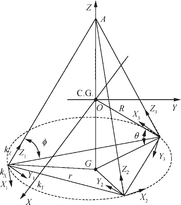
Fig.2 Focal‘ring-shaped” vibration isolation system.
2.2.Modeling CMG system with isolators
The pyramid array CMG system with vibration isolators used in this paper is shown in Fig.3.Under each of CMG,there is a vibration isolator.Compared with the conventional pyramid array CMG system,there exist a set of extra angular variables αi,and αiis relative to theith output torque axis.These additional angles are generated by the CMG output torque and the isolator’s flexibility.They can be referred as disturbance angle,which means the angular momentum of isolatedith CMG can be represented asDifferent from the angular momentum hiof the non-isolated system,is also related to the disturbance angle αi.With the disturbance angles,the singularity problem of the CMG systems with isolators can be modeled.
The total angular momentum of the pyramid CMG system with isolator is given by

For the pyramid array with skew angle of β1= β2= β3= β4= β,the angular momentum of the first CMG can be represented as
in the satellite fixed coordinate.
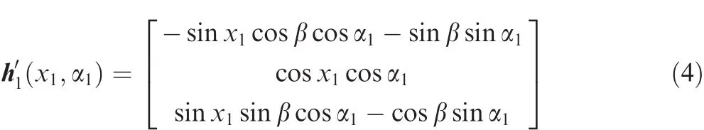
For a well dynamically balanced CMG,α1can be a small angle,and hence there existrelations sinα1≈ α1and cosα1≈ 1.With these two relations,Eq.(4)can be simpli fied as

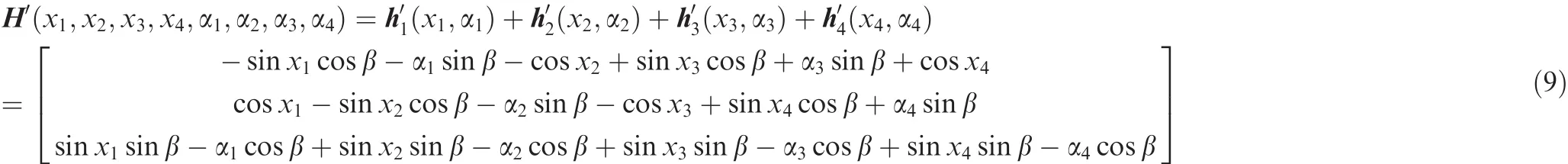
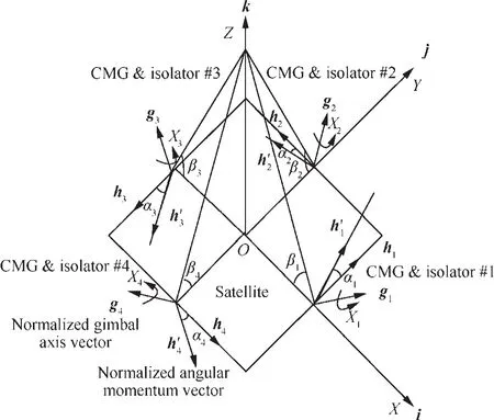
Fig.3 Pyramid array of four SGCMGs and vibration isolators.
3.Disturbance angle calculation
In contrast with the conventional pyramid CMG system,the system with isolators has the disturbance input caused by the CMG ripple and isolator’s flexibility.This section will mainly discuss the disturbance angle αi.
Before deriving the equations of αi,it is assumed that the coupling of the translational motion and rotational motion of the CMG system can be neglected,and only the pure rotation is studied.The moments of inertia of the gimbal frame structures are neglected here,which is a widely applied assumption in the study of CMGs systems and is accurate for typical CMG/spacecraft con figurations.22In the derivation,the well-known Euler’s equations of motion are used and the base( fixed to the satellite)of the CMG isolator is assumed being stationary.When considering the motion of the satellite,the derivation procedure is similar.
3.1.Coordinate systems
The coordinate systems describing rotation of theith CMG with isolator are sketched in Fig.4,whereOxbybzbis the base coordinate system,OxGyGzGis fixed to the spin rotor,andOx1y1z1andOxwywzware the transient coordinate systems which do not participate in the spin rotation of the CMG.
It has the following procedure to realize the rotation from
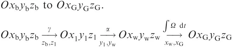
That is,the coordinateOxGyGzGis obtained by rotatingOxbybzbby an angle γ aboutzbaxis,and by an angle α abouty1axis,and then by an angle∫Ω dtaboutxwaxis.The axis below the arrow is the axis of the rotation and the angle above the arrow is the corresponding rotation angle.Among them,xwaxis is conjunction with the CMG angular momentum,zbaxis is conjunction with the initial gimbal axis,γ represents the gimbal angle of the CMG,α is the disturbance angle to be solved and Ω is the magnitude of angular velocity of the spin rotor.Three unit vectors ib,jb,kbare along the three axes of coordinateOxbybzb,respectively.The unit vectors i1,j1,k1,iw,jw,kw,iG,jG,kGare de fined in the same way.
The direction cosine matrices fromOx1y1z1toOxwywzwand fromOxbybzbtoOxwywzware

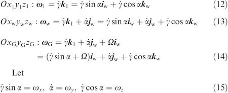
Then with the assumption that theOxbybzbis stationary,angular velocities of the coordinate systems can be expressed as
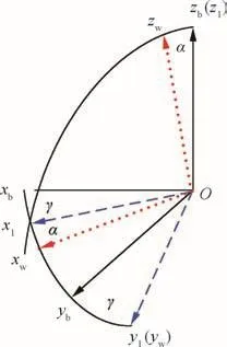
Fig.4 Rotation of the ith CMG with isolator.
3.2.Without considering rotor imbalance
Before the derivation,it is necessary to review the famous Euler’s equations of motion for describing the rotational motion of a rigid body as it will be used later.AnOxyzcoordinate system is used as the reference coordinate,which is generally not fixed on the rigid body.Using the Newton–Euler formulation and the transport theorem,the rotational equation in term ofOxyzbecomes

where the superscript(O)represents the reference coordinate.Or in the column vector form,
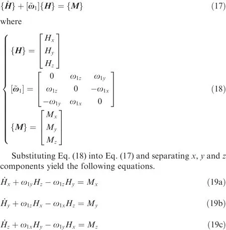
Eqs.(19a)–(19c)are the general form of the Euler’s equations of motion and they also have a simple form if the reference axes are selected as the principal axes.
When the rotor imbalance of the CMG is not taken into account,the principal centroidal moments of inertia of the spin rotor areAw,BwandCw(Bw=Cw),respectively.Then the expression of the angular momentum of the spin rotor has a form of

Selecting theOxGyGzGas the reference coordinate and introducing Eq.(20)into Eq.(19a),there is

whereMxis the sum of the external torque and constraint torque inxdirection.
If usingOxwywzwas the reference coordinate and substituting Eq.(20)andBw=Cwinto Eq.(19b),there is

whereMyis the external torque provided by the isolator and in theOxwywzwit has a simple form as

wherekαis the stiffness of isolator.
Combining Eqs.(14)and(22)with Eq.(23)yields,

Assuming small motions and approximating cosα by 1 and sin α by α,Eq.(24)can be simpli fied as

In Eq.(21),under the condition of ideal constraint,there is

Then

where ω0is a constant.
Introducing Eq.(27)into to Eq.(25),there is

Eq.(28)can be written as

where

Let

Eq.(29)is equivalent to

Notice that compared with the isolation stiffnesskα,Bw˙γ2is
relativelysmall,soitisreasonabletotreatKasaconstantvalue.
Then there is

where

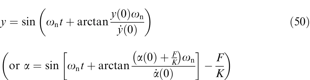
When given the initial condition,

the disturbance angle α has the following solution
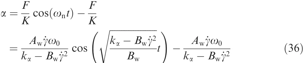
Here the frequency of oscillation is

3.3.With consideration of rotor imbalance
An approach to calculate the disturbance angle considering the imbalance of spin rotor is developed in this section.Note that except for the spin rotor,the gimbal servo system of the CMG also generates random disturbances due to gimbal friction and motor ripple.However,the disturbances are at higher frequencies and with much smaller amplitudes than those induced by the rotary flywheel.1
Generally the rotor imbalance is classi fied into two categories,which are static imbalance and dynamic imbalance.They are de fined as follows.23
(1)Static imbalance:when the imbalanced masses msall lie in a single plane,the resultant imbalance is a single radial force Fs.
(2)Dynamic imbalance:when the imbalance mdappears in more than one plane,the resultant is a force and a rocking moment Md,which is referred to as dynamic imbalance.
The static and dynamic imbalance models of the CMG spin rotor are shown in Figs.5 and 6,respectively.In both Figs.5 and 6,the spin rotor of the CMG rotates at Ωiand the gimbal rate is˙γi.The distance betweenmsand the center of massOiis represented asrsand that betweenmds along the axisxiis represented ashd.
The dynamic imbalance will be considered in this section.For theith CMG with dynamic imbalance shown in Fig.6,there exists dynamic imbalance in the spin rotor,which generates the product of inertia in thexiOiziplane,and the orientation of the angular momentum vector is not in conjunction with the spin axis any more.
Then the inertia matrix of the CMG can be expressed as
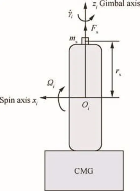
Fig.5 CMG with static imbalance.
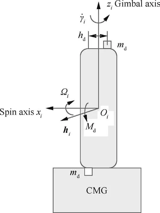
Fig.6 CMG with dynamic imbalance.

Similar to the balanced state,when the initial state α(0)=0 rad,˙α(0)=0 rad/s,
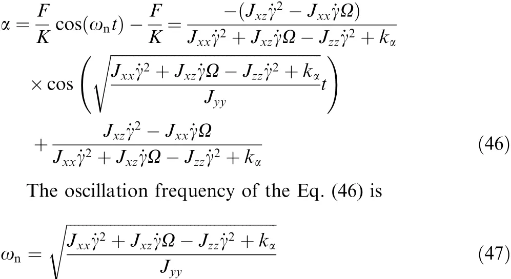
whereJxzis the product of inertia of spin rotor and it has a random value.
3.4.Summary
It can be seen from Eqs.(36)and(46)that in both the balanced state and imbalanced state,the disturbance angle has the formulation of

whereAnis the amplitude of the oscillation.Then the time derivative of the disturbance angle is

It can be seen from Eq.(49)that the amplitude of˙α increases with the increase of the oscillation frequency ωn.From Eqs.(37)and(47),it can also be observed that increasing the stiffnesskαof the isolator results in the increase of the oscillation frequency ωn.That is to say,when the stiffnesskαbecomes larger,the oscillation amplitude of˙α also becomes larger.This conclusion is important for the singularity escape of CMG isolation system,which will be presented in the next section.
When the spin rotor is balanced,parametersAnand ωnare determinable.While in the imbalanced states they are random as the product of inertia of spin rotor is random.
ItshouldbementionedherethatthederivationfromEq.(48)toEq.(49)isbasedontheassumptionthatbothJxz(orBw=Cw)and˙γ are small terms so that ωnhas the same order asIn this way,ωncan be approximately considered as constant.Moreover,Eqs.(46)–(49)are based on the condition of zero initial disturbance,i.e. α(0)=0 rad and ˙α(0)=0 rad/s.In the non-zero initial states,i.e.˙α(0)≠0 rad/s,Eq.(44)canbewritteninthefollowinginitialphaserelatedform as
4.Singularity escape of CMG isolation system
In this section,the disturbance angle rate˙α is considered and assumed to be the form of Eq.(49)when studying the singularity escape of CMG isolation system.
In the proposed system,the time derivative of the angular momentum is represented as

where the second term is the result of bringing in the disturbance angles,and
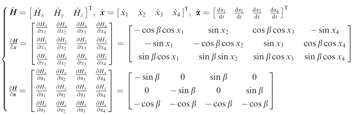
Note that in the conventional pyramid CMG system,there is only the first term,i.e.,˙H=A˙x.Wie9introduced steering logic based on mixed two-norm and least-square optimization.Each column vector of matrix B is a unit vector,which is antiparallel with the normalized gimbal-axis vector gi(i=1,2,3,4).This is a singularity avoidance without considering the disturbance caused by CMG and isolator,so modi fication should be made for the CMG system with the isolators.Moreover,one can see from the Eq.(52)that matrix A does not contain the disturbance angle α and B is a constant matrix only related to the skew angle β.Therefore,the singularities of A are the same as those of the conventional CMGs without isolators,and B has no problem of singularities.
In the proposed system,the actual output torque vector u becomes

Since there exists torque error caused by singularity or disturbance,the torque error is de fined as follow.When the commanded torque τ is given,there is

In this way,the torque derived from α and its derivative can be regarded as the disturbance which can be compensated by the gimbal motion.
Then the steering law design for CMGs with isolators is degenerated into the problem for conventional CMGs without isolators.9The singularity problem can be generally described by the following mixed two-norm and least squares minimization problem

where P and Q are weighting matrixes and they should be properly chosen.
The solution of this problem is

and P and Q are positive de finite matrices and can ensure the non-singularity of the matrix AQ-1AT+P-1.
Notice that when escaping from singularity states with the presented steering logic,P and Q should be appropriately selected to ensure that the resulted torque error is acceptable for the dynamic system of a satell9ite.For more details about the selection of P and Q,see Ref..
Returning to the differential equation Eq.(52),one can see that the equation relates the time derivative of the system angular momentum to the gimbal ratesx˙ as well as the time derivative of the disturbance anglesα˙.Betweenx˙ andα˙,x˙ is the controllable variable which can be calculated with the proposed steering logic,whileα˙ is a stochastic variable created by the isolator’s flexibility.Thus,when magnitude ofα˙ is too large,the system cannot be controlled only byx˙.Furthermore,it is known from the vibration theory that transient vibration of high frequency decays more quickly than the vibration of low frequency if there exists damping.
5.Numerical examples
Numerical examples are presented in this section to examine the singularity avoidance logic of CMG isolation system,which is given by Eq.(57),and to show the in fluences of the isolator on the singularity and the torque error.The time derivative of disturbance angle˙αiis presented in Eq.(49),and the disturbance’s oscillation frequency ωnrelated to isolator stiffnesskαis presented in Eqs.(37)and(47),respectively.

Table 1 Simulation parameters.
A typical pyramid CMG system with isolators is used for the numerical simulation.Table 1 represents the parameters used in the numerical simulation.
Notice that in Eqs.(37)and(47),Eq.(47))is much larger than other terms and ωnis approximately equal toin Eq.(47)).This relationship is presented in Fig.7.If selecting the isolation stiffnessas1000 N·m/rad,the corresponding oscillation frequency is 100 rad/s(15.92 Hz),as shown in Fig.7.In this case the time derivative of αi(Eq.(49))is shown in Fig.8.Fig.9 shows singularity simulation results for the proposed system.
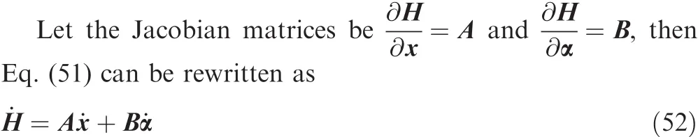
Fig.9(a)illustrates the singularity avoidance performance of the system with proposed steering logic,and Fig.9(c)is the torqueerrorpresentedinEq.(55).ItcanbeseenfromFig.9(a)that the system can successfully escape the singularity during 0–2.21 s.Fig.9(a)alsoshowsthatthetorqueerrorsofthesystem are small during this time interval.From the simulation result onecanseethattheproposedsteeringlogiccanbeusedtoescape from the internal elliptic singularities,which are troublesome problems when using steering logics based on the pseudoinverse method.From Fig.9,one can also see that the system encounters a different singular state x*=[-π/2, -π, π/2, 0]Trad at 2.21 s and then cannot escape this singular state permanently.Because in this singular state,angular momentum of all SGCMGs reaches the maximum value inxdirection of the satellite,which is the direction of the demanded torque[1,0,0]TN·m.This is a reason why it is necessary to add extra degree of freedoms to the CMG system,such as variablespeed CMG(VSCMG)and double-gimbal CMG(DGCMG).

Fig.7 Oscillation frequency as a function of isolation stiffness.

Fig.8 Time derivative of αi(15.92 Hz).
Fig.9 Singularity simulation results for the proposed system.

Fig.10 Total output torque of CMGs.
Fig.10isthetotaloutputtorqueofCMGsduringthesingularity escape.
The maximum value of torque error at different oscillation frequencies was plotted as a function of time in Fig.11.Five hundred simulations were made to test the performance of the proposed steering logic.Oscillation amplitudeAnwas randomized between 0 and 0.001 rad and the initial singular case was selected as[-π/2,0,π/2,0]Trad.Monte Carlo simulation results show that the torque error of system is large near singularity and small otherwise.
An important parameter when designing the CMG isolator is the isolation stiffness,or in other words,the isolation frequency.The relationship between the singular state escape time and oscillation frequency ωnwas plotted in Fig.12,which further indicates the relationship between the escape time and the isolation stiffness or isolation frequency.The simulation result shows that there is no direct in fluence of oscillation frequency on the singularity escape time,which means there is no in fluence of isolation stiffness/frequency on the singularity escape time.
Finally,it should be mentioned that the time of encountering the saturation singularity is also in fluenced by the initial gimbal angles.For example,when the initial state is chosen as x0=[0,0,0,0]Trad,which is the same initial state as the conventional CMGs without isolators in Ref.9,and ωnis selected as 200 rad/s;the time history of gimbal angle is shown in Fig.13.The system encounters the elliptic singular state x*=[-π/2,0,π/2,0]Trad at 1.227 s and encounters the saturation singular state x*=[-π/2,-π,π/2,0]Trad at 3.63 s,while in the first simulation the system encounters the singular state x*=[-π/2,-π,π/2,0]Trad at 2.21 s.

Fig.11 Torque errors at different oscillation frequencies.

Fig.12 Relationship between escape time and oscillation frequency ωn.
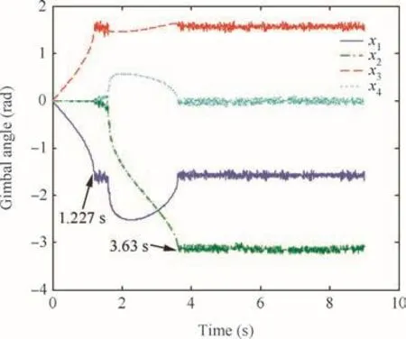
Fig.13 Time history of gimbal angles starting from zero-initial values.
6.Conclusions
In this paper,it is found that the flexibility of the isolator and control moment gyro’s dynamic imbalance can lead to the uncertainty of the angular momentum direction and then affect the singularity problem of the control moment gyro system.
(1)In the study, firstly the formulation of the output torque of a control moment gyro is observed closely with considering the dynamic imbalance of its spin rotor,and then the deformation angle as a result of the isolator’s flexibility is calculated.
(2)With the additional freedoms added by the isolators’flexibility,the total angular momentum formulation of the typical pyramid control moment gyro system with vibration isolators is established.This formulation is used to study the in fluences of isolators on the singularity problem.
(3)It shows that the disturbance angle does not directly affect the conventional Jacobian matrix A,however does add another Jacobian matrix B,which is related to the rate of the disturbance angle.
(4)With this extra Jacobian matrix,a new steering logic is suggested in the present paper,which can be considered as a modi fication to the steering logic for the conventional control moment gyro system.
(5)Numerical simulation results indicate that the proposed steering logic performs well when system encounters the internal elliptic singularities,which are troublesome problems when using steering logics based on the pseudo-inverse method.The simulation also shows that the isolation stiffness has no in fluence on the singularity escape time.The numerical results also indicate that the torque error of the system is large near the singularity but otherwise small.
Acknowledgement
This work was sponsored by the National Natural Science Foundation of China(No.11272172).
1.Christopher EE.A system engineering approach to disturbance minimization for spacecraft utilizing controlled structures technology[dissertation].Massachusetts:Massachusetts Institute of Technology;1990.
2.Guan X.Integrated design of vibration isolation and attitude control for high resolution remote sensing satellites[dissertation].Beijing:Tsinghua University;2012.
3.Cui Y.Experimental modeling and optimization of single-gimbal CMG vibration isolator.Proceedings of the 12th European conference on spacecraft structures,materials and environmental testing;2012 Mar 20–23;Noordwijk,Netherlands.Reston:AIAA,2012.
4.Luo Q,Li DX,Zhou WY,Jiang JP,Yang G,Wei XS.Dynamic modeling and observation of micro-vibration generated by single gimbal control moment gyro.J Sound Vib2013;332(19):4496–516.
5.Luo Q,Li DX,Jiang JP.Coupled dynamic analysis of a single gimbal control moment gyro cluster integrated with an isolation system.J Sound Vib2014;333(2):345–63.
6.Bernhard RJ,Hall HR,Jones JD.Adaptive-passive noise control.Internoise1992;139:427.
7.Zhang Y,Zhang JR,Xu SJ.Parameters design of vibration isolation platform for control moment gyroscopes.Acta Astronaut2012;81(2):645–59.
8.Zhang Y,Xu SJ.Vibration isolation platform for control moment gyroscopes on Satellites.J Aerosp Eng2011;25(4):641–52.
9.Wie B.Space vehicle dynamics and control.2nd ed.Reston:AIAA Inc.;2008.p.466–739.
10.Jones LL,Zeldon RA,Mason AP.Generalized framework for linearly constrained control moment gyro steering.J Guid Control Dyn2012;35(4):1094–103.
11.Yoon H,Tsiotras P.Singularity analysis and avoidance of variable-speed control moment gyros–Part I:No power constraint case.Proceeding of AIAA/AAS astrodynamics specialist conference and exhibit;2004 Aug 16–19;Providence:Rhode Island.Reston:AIAA;2004.p.1–13.
12.Kurokawa H.Survey of theory and steering laws of single-gimbal control moment gyros.J Guid Control Dyn2007;30(5):1331–40.
13.Bedrossian NS,Paradiso J,Bergmann EV,Rowell D.Steering law design for redundant single-gimbal control moment gyroscope.J Guid Control Dyn1990;13(6):1083–9.
14.Oh H,Vadali S.Feedback control and steering laws for spacecraft using single gimbal control moment gyro.J Astronaut Sci1991;39(2):183–203.
15.Ford KA,Hall CD.Singular direction avoidance steering for control moment gyros.J Guid Control Dyn2000;23(4):648–56.
16.Wie B,Bailey D,Heiberg CJ.Singularity robust steering logic for redundant single-gimbal control moment gyros.J Guid Control Dyn2001;24(5):865–72.
17.Wie B.New singularity escape and avoidance steering logic for control moment gyro systems.2003.Report No.:AIAA-2003-5659.
18.Paradiso JA.Global steering of single gimballed control moment gyroscopes using a directed search.J Guid Control Dyn1992;15(5):1236–44.
19.Vadali SR,Oh HS,Walker SR.Preferred gimbal angles for single gimbal control moment gyros.J Guid Control Dyn1990;13(6):1090–5.
20.Zhang JR,Luo Y,Liu W,Zhang Y.Mixture steering law design for control moment gyroscopes.Sci China:Phys Mech Astron2014;57(1):138–42.
21.Eugene IR.Passive vibration isolation.New York:American Society of Mechanical Engineers(ASME);2003.p.74.
22.Yoon H,Tsiotras P.Singularity analysis of variable-speed control moment gyros.J Guid Control Dyn2004;27(3):374–86.
23.William TT,Marie DD.Theory of vibration with applications.5th ed.Beijing:Tsinghua University Press;2005.p.56.
杂志排行
CHINESE JOURNAL OF AERONAUTICS的其它文章
- Plastic wrinkling prediction in thin-walled part forming process:A review
- Progress of continuously rotating detonation engines
- Microstructure control techniques in primary hot working of titanium alloy bars:A review
- A hybrid original approach for prediction of the aerodynamic coefficients of an ATR-42 scaled wing model
- Dynamic modeling and analysis of vortex filament motion using a novel curve- fitting method
- Boundary-layer transition prediction using a simpli fied correlation-based model