An investigation of tip vortices unsteady interaction for Fokker 29 propeller with swirl recovery vane
2016-11-21LiQingxiWangYangangEitelerg
Li Qingxi,Wang Yangang,G.Eitelerg
aSchool of Power and Energy,Northwestern Polytechnical University,Xi’an 710072,China
bAerospace Engineering,Delft University of Technology,Delft 2629 HS,The Netherlands
1.Introduction
Currently advanced turboprops are once again considered as fuel ef ficient alternatives for turbofan propulsion,since they offer up as much as 10%–30%increment in the propulsive ef ficiency when compared with the turbofan counterparts.1The propeller is typically highly loaded,producing strong turbulent wakes as well as tip vortices trailing from the tips of the propeller blades,and severe interaction can be expected on whatever works in the slipstream of an upstream propeller.Many studies have shown that the unsteady interaction between the upstream propeller and the downstream components is strong enough to in fluence the performance of the propulsion system.
For a typical tractor single-rotation propeller(SRP)con figuration,part of the wing is immersed in the slipstream.The propeller-wing interaction due to the high swirl velocities may dramatically alter the lift distribution over the wing,and thus in fluence the performance of the aircraft.The numerical results from Thom and Duraisamy2showed that the computed airloads on the wing sections immersed in the propeller slipstream are subject to a high level of unsteadiness,where the sectional lift and drag vary signi ficantly during a propeller rev3-olution.Another effort has been conducted by Marretta et al.Flow visualization and unsteady pressure measurements were conducted by Johnston and Sullivan4,5,which yielded an explicit picture of the motion of the propeller tip vortices as they passes over the wing.A brief description can be made that the propeller tip vortex deforms at the wing leading edge in spanwise direction,which was followed by a sever at the leading edge due to viscous effects;after experiencing signi ficant spanwise and chordwise displacements while passing across the wing,it finally reconnects at the trailing edge.The flow field of an 8-bladed propeller slipstream in full installation configuration was visualized by Roosenboom et al.6using both Particle image velocimetry(PIV)technique and computational predictions.Their results depicted that the slipstream changed dramatically because of the presence of the wing,moreover the strong turbulent flows were convected on the wing surface creating new vortices after interacting with the boundary layer of the wing.
Counter-rotating open rotor(CROR)has become an active topic due to its higher propulsive ef ficiency compared with SRP.More unsteady effects are raised due to the introducing of a second rotor.Sturmer et al.7observed a periodic fluctuation of blade loading for the forward rotor in the CROR configuration,and much stronger oscillation is seen in the aft blade loadings which are caused by the impingement of the front blade wakes and tip vortices.Later on,Sturmer8also analyzed the blade forces on a similar CROR model.The aerodynamic impacts from the front-rotor on the aft-rotor were numerically analyzed in terms of the harmonic loads by Soulat et al.9,and further two acoustic analogies were successfully applied to the CROR at approach conditions.Flow visualization in Ref.7shows that the winding effect observed in the propeller/stator interaction also presented in CROR,and the second stage imparts a distortion in the tip vortex of the first stage.However,some inherent flaws of CROR impose much restriction of wider application of the new system,some of which are increases in both the weight of the propulsion system and the interaction noise of the counter-rotating stage,as well as additional complication in the structural form.
Swirl recovery vane(SRV)was first proposed by NASA10on the purpose of obtaining higher ef ficiency to maintain the ability of recovering swirl without the complexity of a CROR which comes to a compromise between aerodynamic performance and structural complication level.By using SRV,a 2%ef ficiency increment compared to the isolated propeller was achieved at free stream Mach number 0.8(Ma=0.8)and 4.5%atMa=0.7,additionally,introducing SRV can shift the peak of the propeller ef ficiency to a higher operating speed without any extra remarkable noise.11However,the researches on SRV were terminated in NACA project,so there is still a lack of open literature available on this topic.

Fig.1 Geometry and computational model.
A set of SRV(as shown in Fig.1(a))was designed for the Fokker 29 propeller at takeoff condition in authors’previous work12and the numerical results show that the swirl behind the propeller was recovered signi ficantly for varying working conditions and the combination of rotor and vane produced 5.76%extra thrust at the design point.
As mentioned above,the unsteady interaction between the propeller and SRV may cause a great variation in the propulsive performance.In a combination of rotor/stator model,unsteady effects are expected to be strong for the relative movement between the two blade rows.Three dominant causes of unsteadiness may exist in this con figuration.The first is wake/stator interaction in which the wakes produced by a rotor row upstream are then swept downstream into the next stator row.The second is vortex shedding at trailing edges and blade tips.The third is the potential rotor/stator interaction in which the pressure field associated with the leading edge of a stator sweeps past the trailing edge of the upstream rotor,causing additional unsteadiness at the trailing edge and possibly affecting the vortex shedding mechanisms.
In this paper,the transient flow field of the propeller/SRV combination is simulated based on the SRV presented in the previous work to get a deep insight of the interaction patterns of the propeller and SRV.The distinct flow structures are depicted in detail and the unsteady effects of the rotor/stator interaction are analyzed.
2.Numerical strategy
2.1.Propeller model and design of SRV
A scale model of the 8-bladed tractor propeller on Fokker 29 airplane is employed here with a diameter ofD=0.3048 m,incidence angle at 3/4Rbeing set to 40°and hub radiusrhub=0.042 m.13whereRis the radius of the propeller.
The SRV was designed under the condition ofJ=1.00 andV∞=30 m/s whereJis the advance ratio andV∞the free stream velocity.The distance between the stacking point of rotor and vane was set to 2c0wherec0is the chord length of rotor root.The out flow angle of isolated propeller at this position was collected as the in flow condition for SRV,and the incidence angle was chosen at-2.5°.Multiple circular arc airfoils were adopted to generate blade sections on seven distributed planes.12
The number of rotor blades and stator vanes were set to prime numbers(8 and 7 respectively)in consideration of possibly lower interaction noise,and the stator was chopped,with the diameter at 0.28 m(91.86%of the propeller),to escape from the tip vortex emanated from the rotor blades,which is shown in Fig.1(a).
2.2.Meshing strategy
The grid-independence study was performed in previous work,12which consists of a physical domain independence work to determine the calculation domain,and a study of amounts and distribution of grids to decide the final meshing strategy.The final mesh is quoted as follows.The inlet(outlet)was 0.65 m upstream(downstream)from the origin,while the outer boundary was set as far as 2R.The hub extended to the inlet and outlet boundary to gain relief in both grid generation and numerical solution.
What becomes improved is that the grids are divided into two parts for each row,i.e.the blade regions and the far field regions(as shown in Fig.1(b)),for the sake of better mesh quality.The blade regions reach as far as 0.16mn spanwise,with the far field regions extending to the outer boundary at 0.3048 m(2R).The final grids amount to 3.3 million,consisting of 1.4 million for each blade region and 0.23 million for each far field region.
2.3.Numerical methods
The numerical simulation was performed under the condition ofJ=1.00,which means the free stream velocity is 30 m/s,while the rotation speed is 5915 r/min corresponding toJ=1.00.Thetransientthree-dimensional(3D)Navier–Stokes equations coupled with Shear stress transport(SST)turbulence model were solved with CFX flow solver.The rotor passing period for one passage was subdivided into 20 physical time steps,using 30 pseudo time steps to converge the solution.
Ultimately,a true transient prediction of the rotor–stator combination can be achieved by simultaneously solving all blade passages of the entire machine;however the penalty of such a computation is not worth a try considering the preliminary exploration of the open rotor–stator interaction.
Time accurate simulation was also possible on the onepassage per component setup even though the pitch lengths of the adjacent rows differ.The Transient rotor–stator(TRS)implementation allows for modeling a single blade passage per row by imposing standard periodicity on pitchwise boundaries and automatically stretching or compressing the flow pro file across the rotor–stator interface.14This variant of the TRS implementation is referred to as the pro file transformation method.It provides a fast and robust approximate transient solution without the need for geometrically scaling error.But as can be expected the phase lag boundary conditions cannot properly resolve unsteady features at frequencies different from the blade passing frequency.

Fig.2 Pressure and thrust history of transient solution.
2.4.Convergence history and comparisons with steady results
The convergence for the unsteady simulation has been evaluated by monitoring the periodicity of two pressure probes signals located on the rotor pressure side(P.S.)and stator suction side(S.S.),as well as the thrust of the two blades.The solution was initialized by the steady results and considered to be converged when the time histories reach a periodic state as those in Fig.2.Each signal reaches a periodic state after about 80 steps.
The mesh distribution for each blade is kept the same with that in the previous work which has already been validated with experimental datas in Ref.12.To give more con fidence in the employment of the meshing and calculation strategy mentioned above,the time-averaged total thrust coef ficient was evaluated and compared with the steady result in previous work.12As can be seen in Fig.3,good agreement is observed between two consequences,which offer a convincing veri fication of the computational-cheap TRS method in the simulation of two blade rows with unequal pitch angles.
3.Unsteady interaction of upstream propeller with downstream SRV
3.1.Variations of propulsive quantities
The propulsive performance during one blade passage passing period is evaluated by the thrust coef ficient of rotor and stator(CT,RotorandCT,Stator),the torque coef ficient of the rotor(CQ,Rotor)and the ef ficiency of combination(ηTotal),as shown in Fig.4(1–20 steps in this figure correspond to the 181–200 steps in Fig.2).The maximum and minimum values were compared with the time-averaged results shown in the form of percentages.Here,the thrust coef ficientCT,torque coef ficientCQand propulsive ef ficiency η were de fined as


whereTis the thrust,Qthe torque,nsthe rotation speed,Dthe diameter of the propeller,and ρ the density of the fluid.
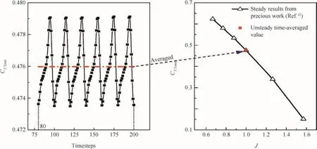
Fig.3 Comparison between steady and unsteady results of total thrust coef ficient.
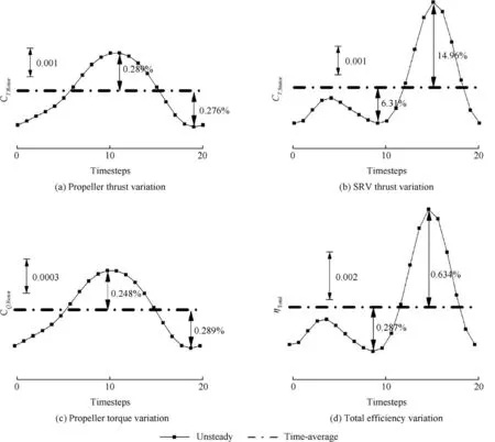
Fig.4 Variations of propulsive quantities during one period.
It can be seen from Fig.4(a)and(c)that both the unsteady thrust and torque coef ficient of the propeller(CT,RotorandCQ,Rotor)have a 0.55%variations with respect to the averaged value,which results from the potential disturbance from the downstream SRV as well as the unsteadiness.Even though this data lies within the range of the relative error of the numerical simulation,it is still a robust indication of the relative variation of the propeller performance in one computational period.A potential disturbance will be elicited when the vane experiences a sudden change in the angle of attack,caused by the passing of the rotor blade wake,causing the aerodynamic field around the vane to be altered as well.The emitted effect of the potential field would be felt by the upstream blade at a time delayed from the disturbance emission time,due to the acoustic propagation speed of a potential disturbance.15Apart from the changing potential field around the stator,the relative motion between the rotor and stator will further enhance the variation of the rotor performance.Moreover,CT,Rotorpeaks at aboutt/T=0.55 which indicates that the vane oriented just behind the rotor at this moment,allowing for the most severe disturbance of the potential field.While att/T=0.95,the rotor provides the smallest thrust which is indicative of the farthest position from the stator.Similar tendency has also been observed inCQ,Rotor.
From Fig.4(b)and(d),a larger relative fluctuations(21%)are observed inCT,Statorwhen compared to theCT,Rotor,additionally,the temporal thrust coef ficients have a different tendency of the rotor.Such a phenomenon can be regarded as a result from severe interaction effects that are imposed on the downstream SRV.Except for the potential field disturbance from the rotor,the wakes as well as the rotor-generated tip vortices also contribute to the unsteadiness of the vane loading.With much lower thrust created by the stator(the thrust of stator is only about 5%of that of propeller),the SRV quantities are bound to show much more sever relative variations.The total propulsive ef ficiency shows a very similar variation withCT,Statorsince the main changes of thrust come from the stator.The total performance of the rotor/stator combination is dominated by the stator from this point of view.
It can be seen from Fig.4 that theCT,Statoris subject to totally different phase angle compared withCT,Rotor,possibly for the reason that stronger effects are essential for the blade wake or rotor tip vortex rather than the potential disturbance.CT,Statorreaches its largest value att/T=0.75 and at this moment the propeller wake impinges directly on the leading edge of SRV.
3.2.Thrust distribution of propeller and SRV
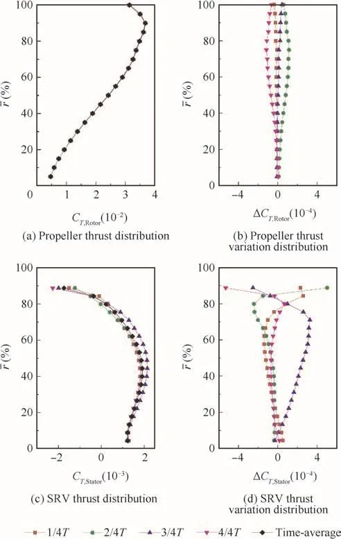
Fig.5 Thrust distributions of propeller and SRV.At four time instants(t/T=0.25,0.50,0.75 and 1.00)and time-averaged result.
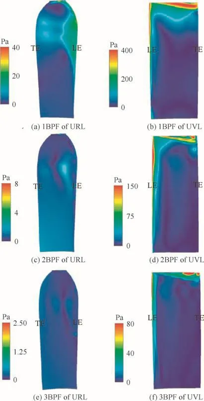
Fig.6 Load harmonics of rotor blade and stator vane.
The time-averaged thrust distributions along the radius of the propeller and the SRV at four time instants are shown in Fig.5(a)and(c)in order to identify the thrust fluctuations.As seen in Fig.5(a),the propeller thrust of different time instants almost overlap with each other( fluctuation:0.55%referring to Fig.4),which indicates that the unsteadiness of the rotor is relatively small.The variations of the aforementioned time instants ofCT,Rotorcompared to the time-averaged distribution are depicted in Fig.5(b).A symmetric behavior is observed with respect to ΔCT,Rotor=0,which can be expected from the periodic flow on the rotor surface as well as the potential disturbance from the downstream vane.The portion of the rotor which undergoes high unsteadiness is located within the range of 60%–80%of the blade radius.Different from the rotor case,the thrust fluctuations of the stator is more noticeable as shown in Fig.5(b)and(d).The maximum thrust of the stator is located at aboutr=50%,whereris the nondimensional radius,and even negative thrust exists beyondr=80%.More further work is expected for better design of SRV with optimized thrust distributions,and these unsteady results can however provide further signi ficant reference for the optimization.Like in Fig.5(b)and(d)shows the relative change distributions ofCT,Statorat four instants,while no symmetric shape is observed.Att/T=0.75,positive changes extend to almost full span except forr>83%,and the peak of the stator thrust appears around this moment(see Fig.4).The stator loading shows almost no change belowr=60%att/T=0.25,0.50 and 1.00,but large difference only occurs att/T=0.75.This is maybe caused by the wake de ficit impingement at this time on the stator leading edge which leads to a totally different working condition for the stator.One thing to be noticed is that the dramatic fluctuations appear abover=80%,and the maximum amplitude is around twice of that in lower radius.The reason might lie in that the stator is immersed in the slipstream of its front oriented propeller and effected by the periodically shedding vortices from the rotor.
3.3.Load harmonics of rotor and vane
The unsteady pressures on rotor blades and stator vanes is normally working as a direct indicator of the rotor/stator interaction,and as a main factor of the noise generation and structural vibration.The first three harmonics of unsteady rotor load(URL)and unsteady vane load(UVL)on the suction side of rotor and stator are presented in Fig.6.The frequencies used for the decomposition are the blade passing frequency(BPF)and its harmonics frequencies.

Fig.7 Dynamic pressure pro files at three axial positions atr=50%,projected on cylindrical surface.
Considering the first unsteady load harmonic,the maximum pressure fluctuation over the vane is around ten times stronger than that on the rotor,which indicates that the wakes from the rotor impinging on the stator are much more energetic than the interaction of the potential effects with the rotor.For the rotor,the fluctuations are mainly concentrated near the outer part of the leading edge,same tendency can also be found in Fig.5(b).While for the stator,the unsteady loads are located typically near the leading edge due to the periodic sweep of the rotor wake.The effects of the front tip vortex are particularly clear here,maximizing the pressure fluctuation above 80%of the span over the whole chord.The fluctuations associated with the second loading harmonic 2BPF decrease progressively.Again,the levels seen on the stator vane remain much higher than on the rotor blade.The topology on the rotor is slightly different from the one observed from 1BPF,with the maximum fluctuations located at mid-chord within 60%–80%span.And the third harmonic of the blade has declined to almost zero throughout the whole suction surface.All higher harmonics for the stator have the same shape as the first harmonic.Although the pressure side of the rotor is directly affected by the potential disturbance from the downstream vane,the order of the magnitude is not as large as that of the suction side,so it is not shown here for brevity.The unsteadiness of the rotor is mainly determined by its own period flow instead of the potential disturbance from the downstream SRV.While for the stator,the interference from upstream,i.e.the wake de ficit and the rotor tip vortex,is paramount,and the unsteadiness of the vane tip vortex is also nonnegligible.
3.4.Potential in fluence and wake effects from propeller
As described in the introduction,there are three dominant causes of unsteadiness for the rotor/stator con figuration.The potential in fluence and wake effects may play the dominant role at the mid-span where it is considered to be far enough from the range of tip vortex in fluence.
Fig.7 shows the dynamic pressure pro files at three different axis positions,i.e.0.5c0in front of the propeller,0.5c0in front and behind the SRV.Again,four time instants in one period are chosen to provide a brief impression of the wake effects and the potential disturbance of both the rotor and the stator.The potential effects of the rotor can be easily recognized in front of the propeller.A sinusoidal variation is seen at the upstream of the propeller,with the period length coherently dependent on the number of rotor blades.As expected,no potential disturbance from the stator is observed here.A pronounced wake de ficit is observed between the propeller and its back mounted stator,sweeping along the rotation direction periodically leading to great fluctuations on the stator vanes as in Fig.6.Despite of the same shape,the rotor wake att/T=0.50 is subject to higher dynamic pressures,a direct result of the heavier blade loading at this moment.The potential effects of the stator are also available here,performing as a valley region which is circled and marked as Vane Blockage in the picture.At the downstream of the stator,the dynamic pressure pro file is dominated by the stator wake with a sharp hollow just behind the vane trailing edge.Obviously,the abrupt decrease of the pressure implies a strong wake for the stator and maybe too heavy load for the latter part of the vane,which provides a potential improvement in the further optimization.

Fig.8 Contours of iso-surface of Q=0.00035 around the stator tip region at different time instants:where LE stands for leading edge.
3.5.Interactions between rotor/stator tip vortices
As shown in Fig.6,strong oscillation appears at the stator tip region due to the direct impingement of the rotor tip vortex.Considering the high gradient of the flow quantities around it,the rotor tip vortex may be reconstructed in the vicinity of the stator tip region.The vortex structures in the present study were determined with theQ-criterion16to identify the presence of vortex cores.Since theQvalue is the second invariant of the rate of deformation tensor and becomes positive when the Euclidean norm of the vorticity tensor becomes greater than that of the rate of strain,it can be employed to identify the location of the vortex cores and can offer more abundant information about the local flow field.The vortex structure around the stator tip is visualized in Fig.8 at different time instants.The slices with zebra stripes illustrate the pressure distribution surrounding the rotor tip vortex tube,with low pressure at the center and high pressure on the outskirts.
As the propeller tip vortex moves toward the vane leading edge,it progressively deforms until the viscous effects in the vicinity of the leading edge cause the vortex filament to pinch off with the segments ending on the pressure and suction surfaces att/T=0.50(see Fig.8(b)).There is a spanwise shear in the tip vortex as the vortex moves along the vane,which is outward on the pressure surface and inward on the suction surface as shown att/T=0.75(see Fig.8(c)).The rotor tip vortex(RTV)has just reached the top of the vane in the spanwise,causing a low pressure region on the suction side of stator which can rapidly increase the pressure difference between the pressure side and suction side.The stator tip vortex(STV)starts exactly at the impingement location of the rotor tip vortex in all cases.The RTV will trigger the STV from this point of view although it is not exactly the fundamental cause of it.In the visualization result of Ref.5,the STV winds around the RTV.The scenario is slightly different here that both the RTV and the STV begin to wind around each other behind the stator which is indicative of the similar strength of RTV and STV.
4.Discussion of unsteady effects with different SRV heights
As demonstrated from the previous section,the rotor tip vortex can signi ficantly in fluence the flow structure around the vane tip region and thus the performance of the SRV.It is therefore,preferred to optimize such interaction to improve the overall propulsive performance of the rotor–stator con figuration.With different vane heights,the RTV and STV have changeable relative locations,of which the situation may change dramatically of the interaction between two blade rows due to the separation of the trigger effects.A longer and a shorter SRV were designed to check this phenomenon.

Fig.9 Total performance for different vane heights.

Fig.10 Vortex visualization of long vane and short vane at four time moments in one period.
As depicted above,when the SRV diameterDSRVis set as 0.28 m which is 91.86%of the propeller diameterD,thereafter denoted as medium vane,the RTV impinges on the top of the SRV and strong interaction is observed with the STV.Therefore it is expected for the RTV to impinge on the valve surfaces directly when theDSRVis chosen as 100%ofD(DSRV=0.3048 m),which will be called long vane.The interaction may also be reduced with lower SRV allowing for the STV immersing in the main flow of the propeller slipstream,for which caseDSRVis 0.2552 m corresponding to 83.73%ofD.
4.1.Comparison of propulsive performance
Fig.9 shows a comparison of aforementioned three types of SRV in terms of propulsive quantities.Only qualitative relations are described instead of accurate quantitative presents.As can be seen from the picture,all of the parameters experience the similar changes.Again,the rotor thrust and torque coef ficients show much lower changes for each case,and little discrepancy exists among different cases.As for the stator,the Long Vane shows the best performance characterized by the largest thrust coef ficient as well as the total ef ficiency at most instant moments as well as the time-averaged results.
4.2.Vortex structures for different vane types
With different types of vanes,the rotor tip vortex is designed and expected to interact with the downstream SRV in different patterns.The vortex structures of long vane and short vane are visualized atQ=0.00035 in Fig.10 at four time moments during one flapping cycle to get a comprehensive impression of different patterns.
What should be noted first is that the vane heights do not have a noticeable effect on the propeller slipstream topology in the upstream so that the rotor tip vortex arrives almost at the same spanwise location.For the long vane,the RTV pinches off right at the vane leading edge,and misalignment is also clear at the trailing edge due to the spanwise shear as observed in Fig.8.The rotor vortex filaments on both sides exhibit a trend of reconnection which can be deduced from the deformation further downstream the SRV,and the same phenomenon was also observed in the interaction between the propeller vortex and the wing described in Ref.13.The properties of the stator tip vortex in terms of shape and shedding position show little discrepancy among separate moments which is indicative of the weaker interaction with the RTV.In the short vane case,the RTV is cut off by the vane tip trailing part and great attenuation is apparent though the reason is not clear yet.
4.3.Thrust distribution for different SRVs
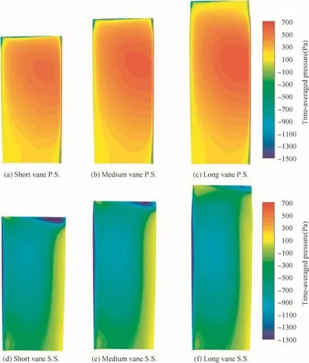
Fig.11 Contours of time-averaged pressure on P.S.and S.S.of three types of SRV.

Fig.12 Time-averaged thrust distribution for three types of SRV.
With distinct interaction patterns between RTV and STV,a noticeable disparity of pressure distributions for different SRVs is predictable.The time-averaged pressures are contoured in Fig.11 on both pressure and suction surfaces of the three types of vanes,i.e.long,medium and short vanes.The difference is apparent probably due to the rotor vortex interaction with different vanes,as well as the in fluence of the vane heights.Broader spanwise range is observed for the long vane of the high-pressure region on the pressure surface and the low-pressure region on the suction surface,probably leading to a larger thrust at this part.While at the tip region,the pressure has the similar distribution as a result of the vane tip vortex.
Under the circumstances of pressure distribution,the timeaveraged thrust distributions of three SRVs are explored in Fig.12.As can be seen from the picture,the mid-span part of the long vane is subject to larger thrust as expected,and the tip regions of all three kinds have similar shape despite of their separate spanwise locations.All in all,the long vane appears to have greater thrust in full span,thus leading to a larger thrust coef ficient of stator.
5.Conclusions
(1)The steady solutions and transient results for the combination of the propeller/swirl recovery vane are compared and good agreement is obtained.Larger fluctuations of thrust coef ficient are observed on the stator so that the variations of the total ef ficiency depend mainly on the stator working performance.
(2)The transient surface pressures of the rotor/stator are decomposed into the blade passing frequency and the first three harmonics are presented.The unsteady load of the stator is about ten times that of the rotor.Large changes appear at the vane leading edge due to the potential disturbance as well as the wake effects of the upstream propeller.Much larger fluctuations occur at the vane tip region as a result of the interaction between the rotor/stator tip vortices.
(3)Despite of the shorter vane height,the RTV impinges directly on the top of the vane due to the slipstream contraction.The development of the vortex structure is depictedatfourinstantaneousmomentsandobservations canbemadethattheRTVpinchesoffatthemid-chordof thevanetopsection,andmisalignmentoftherotorvortex if laments is also clear resulting from the spanwise shear.The RTV has a signi ficant effect on the stator tip vortex by impinging on the vane top where the STV starts.Winding effects are visible on two tip vortices which is indicative of the similar strength of them.
(4)A longer and a shorter SRV are generated based on the original case to explore different interaction patterns for the rotor/stator tip vortex.As for the long vane case,the RTV pinches off at the vane leading edge and a trend of reconnection is observed behind the SRV.Abrupt attenuation of the rotor tip vortex is apparent with the Short Vane though the reason is not clear yet.Both of the cases show weaker in fluence of the RTV on the stator tip vortex.
Acknowledgements
This work was supported by the National Natural Science Foundation of China(No.51376150).The assistance from the China Scholarship Council is of great appreciation.
1.Mitchell GA,Mikkelson DC.Summary and recent results from the NASA advanced high-speed propeller research program.Proceedings of the 18th joint propulsion conference;1982 Jun 21–23;Cleveland,OH.Reston:AIAA;1982.
2.Thom A,Duraisamy K.Computational investigation of unsteadiness in propeller wake-wing interactions.J Aircr2013;50(3):985–8.
3.Marretta RMA,Davi G,Lombardi G,Milazzo A.Hybrid numerical technique of evaluating wing aerodynamic loading with propeller interference.Comput Fluids1999;28(8):923–50.
4.Johnston RT,Sullivan JP.Unsteady wing surface pressures in the wake of a propeller.J Aircr1993;30(5):644–51.
5.Johnston RT,Sullivan JP.Propeller tip vortex interactions.Proceedings of 28th Aerospace sciences meeting;1990 Jan 8–11;Reno Nevada.Reston:AIAA;1990.
6.Roosenboom EWM,Sturmer A,Schroder A.Comparison of PIV measurements with unsteady RANS calculations in a propeller slipstream.Proceedings of 27th AIAA applied aerodynamics conference;2009 Jun 22–25;San Antonio Texas,USA.Reston:AIAA;2009.
7.Sturmer A,Carlos O,Gutierrez M,Roosenboom EWM,Schro¨der R,Geisler R,et al.Experimental and numerical investigation of a contra rotating open-rotor flow field.J Aircr2012;49(6):1868–77.
8.Sturmer A.Unsteady CFD simulations of contra-rotating propeller propulsion systems.Proceedings of 44th AIAA/ASME/SAE/ASEE joint propulsion conference&exhibit;2008 Jul 21–23;Hartford,CT.Reston:AIAA;2008.
9.Soulat L,Kernemp I,Sanjose M,Moreau S.Assessment and comparison of tonal noise models for counter-rotating open rotors.Proceedings of 19th AIAA/CEAS aeroacoustics conference;2013 May 27–29;Berlin,Germany;2013.
10.Gazzaniga JA,Rose GE.Wind tunnel performance results of swirl recovery vanes as tested with an advanced high speed propeller.Proceedings of AIAA/SAE/ASME/ASEE 28th joint propulsion conference and exhibit;1992 Jul 6–8;Nashville,TN.Reston:AIAA;1992.
11.Dittmar JH,Hall DG.The effect of swirl recovery vanes on the cruise noise of an advanced propeller.Proceedings of AIAA 13th aeroacoustics conference;1990 Oct 22–24;Tallahassee,FL,USA;1990.
12.Wang YG,Li QX,Eitelberg G,Veldhuis LLM,Kotsonis M.Design and numerical investigation of swirl recovery vanes for the Fokker 29 propeller.Chin J Aeronaut2014;27(5):1128–36.
13.Van Berkel ECR,Kotsonis M,Veldhuis LLM,Eitelberg G.In fluence of non-uniform in flow conditions on propeller performance in tractor con figuration.Delft:Delft University of Technology,AerospaceEngineering faculty;2012.Experimental research report;2012.
14.Blumenthal R,Hutchinson B,Zori L.Investigation of transient CFD methodsapplied to a transonic compressorstage.Proceedings of ASME 2011 Turbo Expo;2011 June 6–10;Vancouver,British Columbia,Canada.New York:ASME;2011.
15.Falk EA,Jumper EJ,Dame N,Haven BA.Upstream-propagating potential waves elicited from the stator row downstream of a fan.Proceedings of the 35th AIAA/ASME/SAE/ASEE joint propulsion conference;1999 June 20–24;Los Angeles,California.Reston:AIAA;1999.
16.Chakraborty P,Balachandar S,Adrian RJ.On the relationships between localvortex identi fication schemes.JFluidMech2005;535:189–214.
杂志排行

CHINESE JOURNAL OF AERONAUTICS的其它文章
- Plastic wrinkling prediction in thin-walled part forming process:A review
- Progress of continuously rotating detonation engines
- Microstructure control techniques in primary hot working of titanium alloy bars:A review
- A hybrid original approach for prediction of the aerodynamic coefficients of an ATR-42 scaled wing model
- Dynamic modeling and analysis of vortex filament motion using a novel curve- fitting method
- Boundary-layer transition prediction using a simpli fied correlation-based model