无刷双馈风力发电机的设计、分析与控制
2016-11-16魏新迟
程 明 韩 鹏 魏新迟
(东南大学电气工程学院 南京 210096)
无刷双馈风力发电机的设计、分析与控制
程明韩鹏魏新迟
(东南大学电气工程学院南京210096)
无刷双馈发电机是一类具有两个交流馈电端口和一个公共机械端口的新型发电机。该类电机易于实现变速恒频运行;由于去除了传统双馈发电机中的电刷集电环,具有可靠性高、维护成本低等优点,同时便于实现有功和无功的近似解耦控制,因而被认为是最有希望取代现有双馈发电机的一种电机类型。该文介绍了现有无刷双馈发电机的基本结构与工作原理,总结了它们的共性特点和个性差异以及当前研究中存在的问题;从电机设计角度对比分析了三种主流无刷双馈发电机的功率密度和转矩密度;对其分析设计方法和控制策略进行了综述,讨论了不同无刷双馈发电机在控制上的统一性;基于对无刷双馈电机设计、建模与控制方面的研究,提出一种可以改善功率密度的新型双定子无刷双馈风力发电机结构,并就独立运行和并网运行两种不同工况提出了相应的控制策略,给出了实验结果。最后对该类电机的应用前景和发展方向进行了展望。
无刷双馈发电机风力发电控制策略设计分析方法内在一致性功率密度转矩密度
0 引言
众所周知,风能已发展成为第二大可再生能源,并且预计到2035年,风能将承担全部新能源发电总量的25%[1]。其中,海上风电凭借风能资源充足、风速高、无土地侵占问题等天然优势成为未来风电发展的必然趋势。然而,高昂的投资成本和复杂的海上环境对风机系统提出了进一步的要求,包括削减成本、提高可靠性和延长使用寿命[2]。目前主流的风力发电机包括永磁同步发电机、电励磁同步发电机和双馈感应发电机(Doubly-Fed Induction Generator,DFIG)[3]。其中,DFIG具有转矩密度高、所需功率变换器容量小、有功和无功功率解耦控制的优点,是当前陆上风电的主流机型。但电刷与集电环的存在不仅使系统可靠性降低,维护成本增加,而且产生额外损耗。以一台1.5 MW双馈风力发电机为例,在20年生命周期内,更换电刷费用约6万元,更换集电环费用约5万元,损耗导致发电收入减少约18万元(按每相损耗1 kW,每年发电6 000 h,电价0.5 元/(kW·h)计算),总费用约30万元。因而,永磁直驱式风力发电机组近年来得到快速发展[4-7]。然而,近年来永磁体价格的剧烈波动使得少永磁或无永磁风力发电机受到更多关注[8],有刷双馈发电机的去刷化成为当前风电领域亟待研究的重要课题。
本文首先回顾了无刷双馈发电机概念的提出和发展历程,针对已提出的多种无刷双馈发电机,分析了各自的结构特征和工作原理,并就三种主要的无刷双馈发电机结构进行了对比,指出了它们在设计方面的共性特点和个性差别。对无刷双馈发电机的分析设计方法和发电控制策略进行了综述,揭示了三种主要无刷双馈发电机在控制方面的一致性,为无刷双馈发电机的统一控制奠定理论基础。在此基础上,提出了一种改善转矩密度的新型双定子无刷双馈风力发电机结构,并研究了其在独立运行和并网运行两种情况下的控制策略,最后对无刷双馈发电机的未来发展进行了展望。
1 无刷双馈发电机结构与工作原理
1.1无刷双馈发电机的分类
无刷双馈发电机最早起源于多相感应电动机的级联运行[9],如图1所示。两台绕线转子感应电机同轴连接,其中一台电机的转子绕组与第二台电机的定子绕组相连,第二台电机的转子绕组通过电刷集电环与起动电阻或调速电阻连接。该结构无需特殊的绕组设计,仅通过开关切换即可获得三个不同的同步转速,满足了人们最早对于调速的迫切需求。L.J.Hunt[9]改进了该系统的接线方式,将转子绕组-定子绕组连接修改为转子绕组-转子绕组连接,不但保持了具有三个同步转速的特点,而且去除了电刷集电环,极大地提高了系统的可靠性。
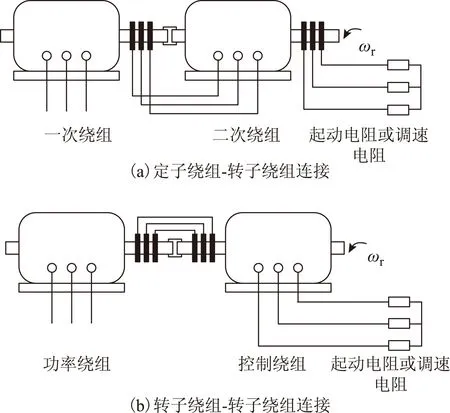
图1 绕线转子感应电机级联运行的演变Fig.1 Evolution of cascaded wound rotor induction machine
这一思想被广泛延伸,陆续诞生了多种新型无刷双馈发电机结构。按照其去刷化的原理可以分为两类:级联式和调制式。级联式是将现有有刷双馈发电机与其他电磁设备级联,采用无接触式电能传输的方式实现转差功率在静止电源与转子绕组之间双向流动。属于这一类型的无刷双馈发电机结构包括级联式无刷双馈感应发电机(Cascaded Doubly-Fed Induction Generator,CDFIG)[10]、旋转变压器式无刷双馈感应发电机(Brushless Doubly-Fed Induction Generator with Rotary Transformer,BDFIG-RT)[11]和旋转电力电子变换器式无刷双馈感应发电机(Brushless Doubly-Fed Induction Generator with Rotating Power Electronics,BDFIG-RPE)[12]。调制式是借助短路绕组或磁阻凸极产生不同极对数的两个磁场分别与两套定子绕组耦合,如嵌套环转子式无刷双馈感应发电机(Nested-Loop Rotor Brushless Doubly-Fed Induction Generator,NLR-BDFIG)[13]、齿谐波绕线转子式无刷双馈感应发电机(Tooth-Harmonic Wound Rotor Brushless Doubly-Fed Induction Generator,THWR-BDFIG)[14]、磁阻转子式无刷双馈发电机(Brushless Doubly-Fed Reluctance Generator,BDFRG)[15]和笼障转子式无刷双馈发电机(Hybrid Rotor Brushless Doubly-Fed Generator,HR-BDFG)[16]。详细的分类如图2所示。
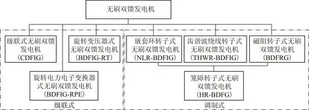
图2 无刷双馈发电机分类Fig.2 Classification of BDFM
1.2级联式无刷双馈感应发电机
CDFIG通过两台绕线转子感应电机同轴级联实现无刷化[10],如图3所示。其基本结构与图1b非常相近,不同之处在于:①图1b所示结构只有一个馈电端口;②图1b所示结构运行于异步工作方式下。用电力电子变换器取代起动电阻或调速电阻便产生了现在的CDFIG。其结构简单,易于实现,可由任意两台绕线转子感应电机级联构成;建模简单,数学模型可由普通异步电机的动态和稳态数学模型按照转子绕组连接方式组合后得到;气隙磁通密度分布正弦度高,电磁转矩平稳,噪声小。从功率流、变换器容量需求、系统效率和电机利用率的角度来看,最佳极对数配合为pp≥pc[17],其中pp和pc分别为功率绕组(Power Winding,PW)和控制绕组(Control Winding,CW)的极对数。但该结构也存在明显的缺点:①轴向长度过长,现有的绕线转子感应电机通常设计为少极对数大长径比结构,而且总的绕组端部长,电机功率密度低;②转子采用绕线结构,导致电阻较大,一方面转子铜耗增加,另一方面异步转矩占总转矩的比例增大,使得双馈同步特性变差。
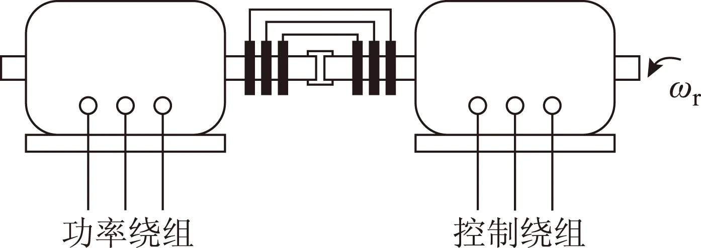
图3 级联式无刷双馈感应发电机Fig.3 Cascaded brushless doubly-fed induction generator
1.3旋转变压器式无刷双馈感应发电机
CDFIG虽然成功去除了电刷和集电环,但转矩成分复杂(两个同步转矩分量,两个异步转矩分量),较之只有同步转矩分量的有刷双馈发电机控制难度增加。为了简化控制,使无刷双馈发电机的特性尽可能接近有刷双馈发电机,WEG公司提出了一种以旋转变压器取代电刷集电环装置的去刷化方案,即旋转变压器式无刷双馈感应发电机[11],如图4所示。

图4 旋转变压器式无刷双馈感应发电机Fig.4 Brushless doubly-fed induction generator with rotary transformer
这一方案利用旋转变压器实现转差功率在旋转绕组与静止电源之间的双向传输。但由于变压器只能传输交流形式的电能,旋转变压器式无刷双馈感应发电机在同步转速下无法实现功率的有效传输,运行中仍要通过控制主动避开该同步转速。
1.4旋转电力电子变换器式无刷双馈感应发电机
文献[12]提出一种使用旋转电力电子变换器的无刷双馈发电机结构。如图5所示,该结构包括一台绕线转子感应电机和一台同轴级联的同步电机。不同于常见的永磁同步电机或电励磁同步电机,该同步电机定子上放置永磁体或直流励磁绕组,转子上安放三相电枢绕组。感应电机转子绕组与同步电机转子绕组通过随轴同步旋转的交-直-交变换器实现电气连接,因而两套绕组中电压电流的幅值、频率和相位都可以不同。该结构可以实现功率绕组侧单位功率因数运行和各种电压跌落条件下的低电压穿越[18,19],因而是一种理论上可行的双馈风力发电机去刷化方案。但其缺点也非常明显:①电力电子变换器随转轴旋转,需要完善的固定和保护措施;②变换器的开关信号是以无线方式(如WiFi、蓝牙)传递给功率变换器的,其可靠性有待研究,尤其当其运行在复杂的电磁干扰环境中。
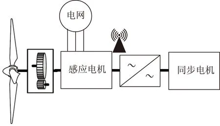
图5 旋转电力电子变换器式无刷双馈感应发电机Fig.5 Brushless doubly-fed induction generator with rotary power electronics
1.5嵌套环转子式无刷双馈感应发电机
NLR-BDFIG是最广为人知的无刷双馈电机结构,而且“无刷双馈电机”这一称呼就起源于该结构类型的电机。为了简化转子绕组,使转子具有传统感应电机笼型转子一样的坚固程度和可制造性,文献[13]提出了该嵌套环转子结构,如图6所示。
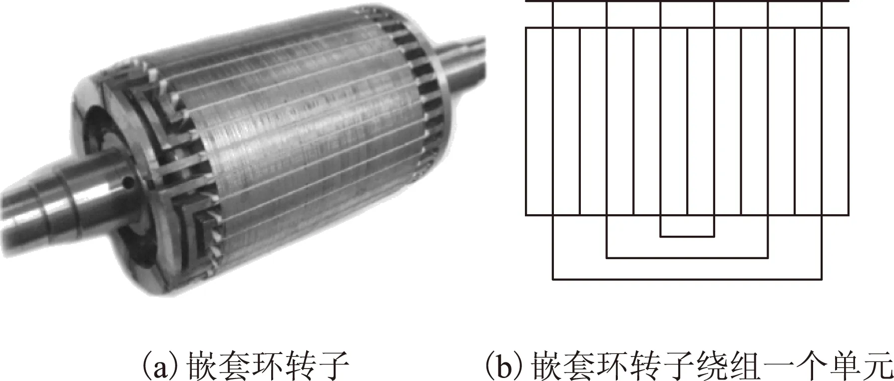
图6 嵌套环转子结构Fig.6 Nested-loop rotor structure
NLR-BDFIG为单定子单转子结构,定子槽内放置两套极对数分别为pp和pc的分布绕组,转子绕组包括pp+pc个重复单元,其中每个单元称为一个巢,且每个巢包括多个嵌套的导体环路。为避免两套定子绕组直接耦合,要求pp≠pc。为了避免产生不平衡磁拉力,进一步要求|pp-pc|>1。
转子上存在多个短路线圈大大增加了该电机结构的建模难度。其全耦合电路模型具有变系数、高阶、非线性的特点[20],模型的降阶工作必不可少。尽管提出该转子结构的初衷在于简化加工制造,但研究表明嵌套环转子绕组并不适合直接铸造,导条与铁心之间必须增加足够的绝缘才能获得理想的无刷双馈特性[21]。而且,不同于传统感应电机中的笼型转子,不同环路导条中的电流密度并不均匀[22]。
然而,NLR-BDFIG气隙中除了两个主要磁场分量外,还存在多种无效谐波磁场分量[23],导致转矩脉动和噪声[24,25]。而且,谐波磁场分量的存在还增加了附加铁耗和铜耗,使铁心容易饱和[26,27],功率密度和比功率降低[28,29]。
1.6齿谐波绕线转子式无刷双馈感应发电机
考虑到NLR-BDFIG转子绕组产生大量低次空间谐波,文献[14]从齿谐波原理出发,通过调整基波和谐波的绕组因数实现保留两种有效频率基波、抑制其他阶次谐波的目标,提出一种双正弦绕组绕线转子。图7为该绕线转子一个单元的短路线圈连接方式。与嵌套环转子相比,不同之处在于齿谐波绕线转子用不等匝分布式闭合线圈组代替等匝同心式短路环,使转子绕组建立的磁动势中除主要磁场外的其他磁场分量尽可能地少,充分发挥了绕组改善磁动势分布和感应电动势波形的功能。该电机大大降低了气隙磁场空间谐波含量,但由于采用不等匝分布式线圈,设计与制造工艺复杂,且转子绕组电阻偏大。

图7 齿谐波绕线转子双正弦绕组一个单元Fig.7 One unit of tooth-harmonic wound rotor
1.7磁阻转子式无刷双馈发电机
文献[15]在提出嵌套环转子式无刷双馈感应电机的同时,注意到磁阻凸极可以代替短路线圈对交变磁通产生相似的阻碍作用,提出一种磁阻转子式无刷双馈电机,即无刷双馈磁阻电机。与同步磁阻电机类似,其转子可采用简单凸极结构[30]、轴向叠片各向异性结构[31]和多层磁障结构[32],如图8所示。研究表明,轴向叠片各向异性转子的磁场转换能力最强,多层磁障转子次之,简单凸极转子最弱[33,34]。但轴向叠片中会感生大量涡流,因而最适合无刷双馈磁阻电机的转子结构为多层磁障转子[35]。
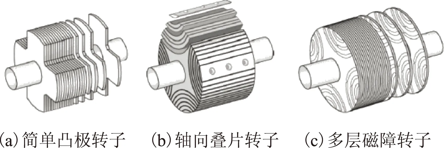
图8 磁阻转子类型Fig.8 Reluctance rotors
1.8笼障转子式无刷双馈发电机
文献[16]提出一种兼具短路线圈和磁障层的笼障转子式无刷双馈发电机,其转子如图9所示。本质上为多层磁障转子与嵌套环转子结构的结合,旨在利用短路绕组和凸极转子的双重凸极性增强转子的磁场转换能力。但短路线圈与磁障层之间存在怎样的相互影响,不同转子结构的磁场转换能力如何衡量还有待进一步研究。由于同时存在饱和与涡流,磁场分布更为复杂,分析时将在更大程度上依赖有限元等数值分析工具。

图9 笼障转子Fig.9 Hybrid rotor
1.9现有无刷双馈发电机的比较
不同结构无刷双馈发电机之间既有共性特点,又有个性差别。其共性主要体现在:
1)无电刷集电环,无永磁。
2)有两个馈电端口和一个机械端口,且两个馈电端口的能量均可双向流动。
3)双馈同步速为
(1)
式中,ωp、ωc分别为功率绕组和控制绕组电流角频率;pp、pc分别为功率绕组和控制绕组极对数。当电机转速ωr=ωs时,电机运行于双馈同步模式。特别地,当控制绕组中的频率为0时,式(1)对应的转速称为自然同步速。
4)当其中一个馈电端口短接时,电机可以工作在异步运行模式。
5)无刷双馈发电机等效极对数多,适合设计为中低速发电机。
6)与有刷双馈发电机通过改变电流(线负荷)调节功率绕组的功率因数不同,无刷双馈发电机通过改变磁通(或磁负荷)调节功率绕组功率因数。
另一方面由于工作原理和实现方式的不同,不同无刷双馈发电机之间又存在个性差别,主要体现在:
7)级联式无刷双馈发电机的极对数配合的选取主要取决于气隙直径比,转矩密度与极对数配合没有确定的关系;但对于调制式无刷双馈发电机,其极对数配合主要受制于电磁关系,从磁场耦合能力的角度考虑适合选取近极配合,但从提高转矩密度的角度考虑远极配合更为有利。
8)级联式无刷双馈发电机具有更加正弦的气隙磁场分布,但对于调制式无刷双馈发电机来说,气隙磁场除了包含两个主要磁场分量外,还存在多种寄生低次空间谐波。
9)级联式无刷双馈发电机的振动行为与传统交流电机相同,但对于调制式无刷双馈发电机来说,由于气隙中存在两种极对数不同的主要磁场,产生了额外的振动模态,且振幅与极对数配合关系密切。远极配合有助于避免低阶振动模态。
2 无刷双馈发电机分析与设计方法
2.1稳态分析
由于无刷双馈发电机属于正弦波磁场电机,其稳态性能主要借助单相等效电路来分析。与单馈感应电机不同,无刷双馈发电机的稳态等效电路为二端口网络。单相等效电路最早被用于研究CDFIG的双馈同步运行原理、运行范围、转矩能力和变换器容量[10,36]。为了计及铁耗,借鉴感应电机中铁耗的分析方法,文献[37]在稳态等效电路的励磁支路两侧并联随转差率发生变化的可变铁耗电阻,并取得良好的计算精度。
NLR-BDFIG由于其特殊的转子结构导致转子绕组产生大量空间谐波,增加了稳态分析的难度。文献[38,39]通过引入复数形式的导体分布函数,对嵌套环转子无刷双馈发电机的阻抗参数和转矩表达式进行了解析推导。文献[40]则用谐波漏电抗计及空间谐波的影响,系统整理了无刷双馈发电机的串联T形等效电路模型,并将其进行适当变形用于参数提取。同样,为了计及铁耗的影响,可以在励磁支路两侧补充随转差率发生变化的可变铁耗电阻[41,42]。尽管现有等效电路可以取得令人满意的转矩计算精度,但还存在无法计算转子导体电流和分离定转子漏电抗的问题。BDFRG由于转子上无绕组存在,稳态模型与有刷双馈发电机类似,可以直接采用有刷双馈的分析方法进行分析。
由于NLR-BDFIG和BDFRG中存在大量空间谐波,用于感应电机稳态性能近似计算的时谐场分析不再适用。而且转子绕组中电流通过感应方式产生,不适合静磁场计算,所以无刷双馈发电机的有限元分析主要使用瞬态场求解[43,44]。对于计算时间有严格限制的场合,等效磁路法和等效电路法都有优势[45,46]。
2.2动态建模
无刷双馈发电机的动态建模方法主要包括耦合电路理论[20,47],两轴理论[47-51]和空间矢量理论[52-54]。但与传统交流电机不同之处在于,气隙中存在两个转速不同的旋转磁场,且旋转方向相对于转子本身相反。采用传统分析方法时,存在模型阶数高、数学推导不够严密直观、动稳态模型彼此隔离的缺点,所以采用螺旋矢量理论对双定子无刷双馈风力发电机进行建模与分析[55]。不同电机分析理论之间的对比见表1。

表1 电机分析理论比较Tab.1 Comparison of analysis theories
由于NLR-BDFIG转子上存在多个短路线圈,其全耦合电路模型中包含6+NS阶电压方程(其中N为单元数,S为每单元嵌套环数),采用双轴模型时阶数降为4+2S,空间矢量模型为2+S阶复数微分方程,进一步模型降阶可以产生与CDFIG相同阶数(3阶复数微分方程,6阶实数微分方程)的结果,并用于控制器的设计。BDFRG的全耦合电路模型为6阶实数微分方程,最简结果为2阶复数微分方程。
2.3设计与优化
无刷双馈发电机的设计与优化主要基于简化稳态等效电路。早期的无刷双馈发电机主要借助已有的感应电机冲片和同步磁阻电机转子,降低部分转矩能力重新设计绕组。但实践发现,由于无刷双馈发电机需要在定子槽内嵌放两套不同极对数的定子绕组,已有冲片难以满足线负荷要求,于是无刷双馈才作为一种独立的电机结构进行设计。
文献[28]采用仅保留转子漏电感的简化模型推导了简化功率尺寸方程,并与有刷双馈和CDFIG在自然同步转速下的输出功率进行比较,指出NLR-BDFIG的功率输出能力低于普通感应电机约25%。文献[56,57]采用串联T形等效电路与等效磁路、等效热路相结合的方法进行无刷双馈发电机的优化设计。文献[58-61]采用稳态相量图推导了BDFRG中的电磁负荷关系,对多层磁障转子无刷双馈发电机进行了系统性优化设计。
2.4转矩密度与功率密度的比较
通过建立适用于双馈发电机(有刷和无刷)的通用功率方程和转矩密度方程,发现三种无刷双馈发电机的转矩密度表达式可统一表示为
(2)
式中,C为转矩密度系数;A为线负荷;B为磁负荷;λp为功率绕组功率因数;η为效率。三种发电机的转矩密度系数分别为
(3)
(4)
(5)
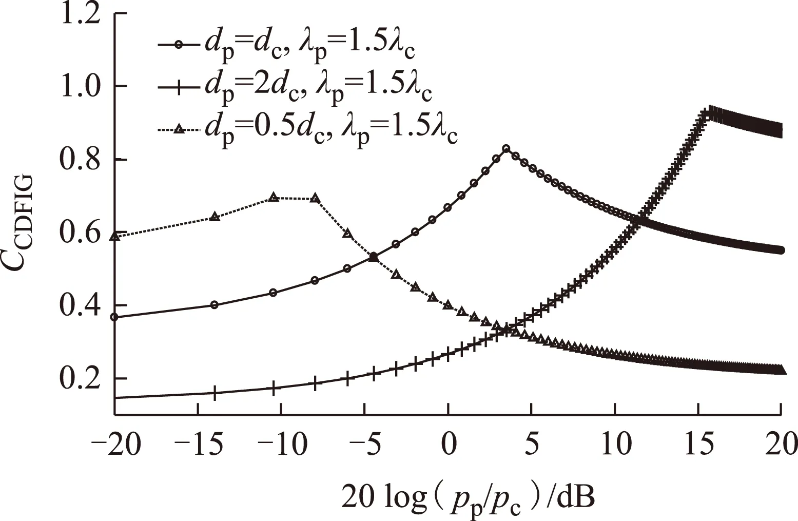
图10 极对数配合对CDFIG转矩密度的影响Fig.10 Influence of pole-pair combination on TRV of CDFIG
式中,n是为计算磁负荷而引入的近似系数,通常n=2可获得很好的近似程度[28];λc为控制绕组的功率因数;dc、dp分别为控制侧和功率侧气隙直径。根据式(3)~式(5)画出极对数配合对三种电机转矩密度系数的影响如图10和图11所示。发电运行中通常要求通过控制绕组调节功率绕组功率因数,即功率绕组功率因数λp与控制绕组功率因数λc不等。在这种运行情况下,CDFIG可以通过选择合适的气隙直径比,在多种极对数配合下得到与传统感应电机相近的转矩密度。而NLR-BDFIG与BDFRG具有相同的转矩密度系数,且转矩密度受极对数和功率因数影响很大。这两种电机适合选择多极对数绕组作为功率绕组,少极对数绕组作为控制绕组以获得更高的转矩密度,如图11所示。因而从转矩密度方面来看,级联式无刷双馈发电机优于调制式,根本原因在于调制式无刷双馈发电机只包含同步转矩分量,而级联式无刷双馈发电机还存在异步转矩分量。

图11 极对数配合对NLR-BDFIG和BDFRG转矩密度的影响Fig.11 Influence of pole-pair combination on TRV of NLR-BDFIG and BDFRG
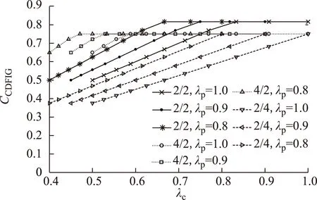
图12 控制绕组功率因数对CDFIG转矩密度的影响Fig.12 Influence of power factors on TRV of CDFIG
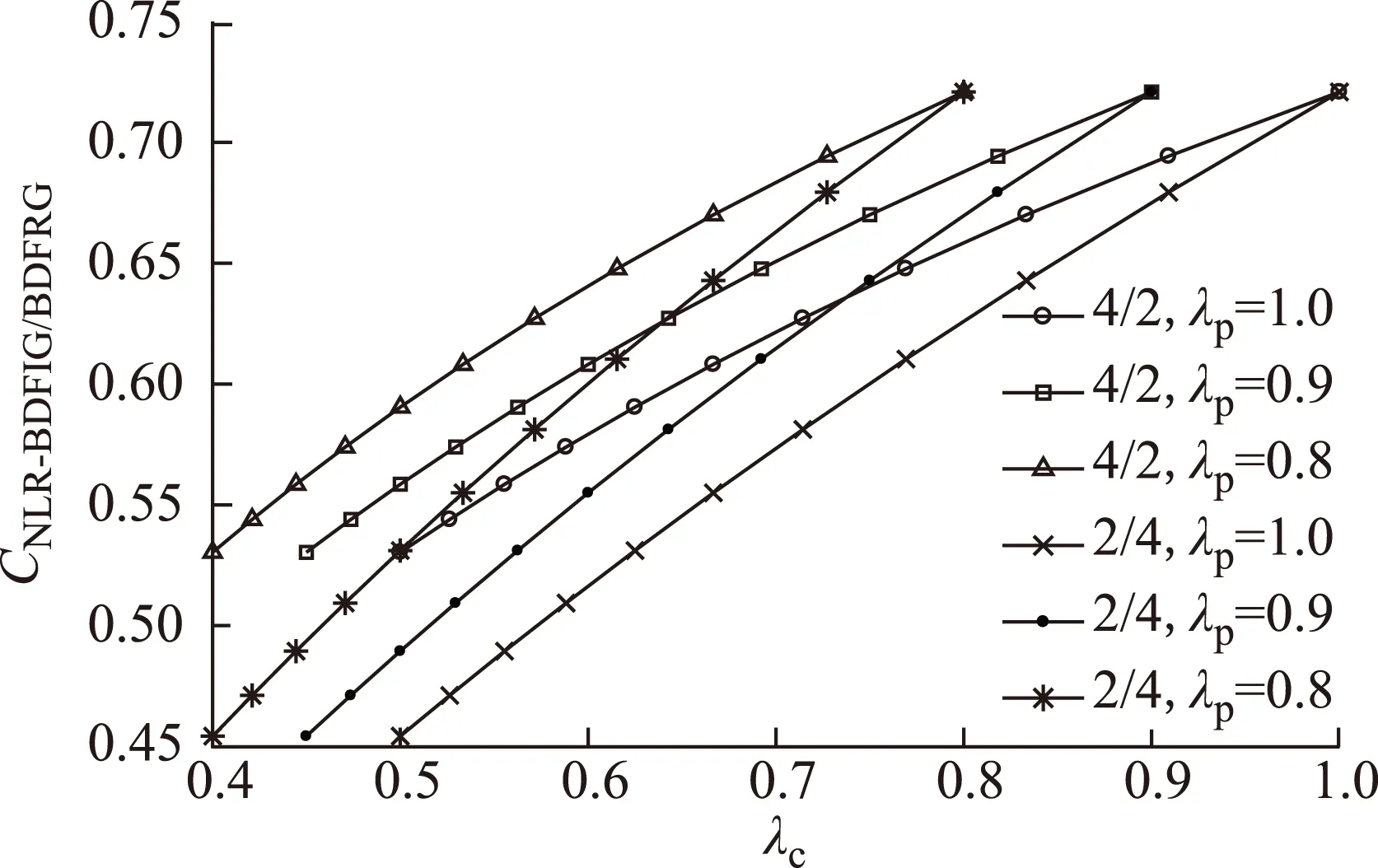
图13 控制绕组功率因数对NLR-BDFIG和BDFRG 转矩密度的影响Fig.13 Influence of power factors on TRV of NLR-BDFIG and BDFRG
控制绕组功率因数对发电机转矩密度系数的影响如图12和图13所示。其中功率绕组功率因数分别设置为1.0、0.9和0.8,极对数配合pp/pc分别设置为2/2、4/2和2/4。从图中可以看出,级联式无刷双馈发电机可以在较宽的控制绕组功率因数变化范围内保持较高的转矩密度系数,而调制式无刷双馈发电机的转矩密度系数随控制绕组功率因数的减小而迅速下降。
3 无刷双馈发电机控制策略
到目前为止,无刷双馈发电机的控制先后经历了闭环标量控制、矢量/直接转矩控制和非线性控制三个阶段。
3.1闭环标量控制
闭环标量控制具有算法简单、实施成本低的优点,因而在闭环控制系统中最先受到研究人员的关注。文献[62]首次提出了针对嵌套环转子式无刷双馈发电机的闭环标量控制,即通过一个PI控制器调节逆变器输出频率来控制电机转速,通过另一个PI控制器调节控制绕组电流幅值来控制功率因数,如图14所示。类似的标量控制被应用于无刷双馈风力发电系统的功率控制[63-65]。由于标量控制是基于稳态关系建立的,无法准确描述电磁转矩和控制变量(控制绕组电压或电流)之间的完整动态关系;而且,转速(有功功率)和功率因数(无功功率)难以实现完全解耦。因而,对无刷双馈发电机使用标量控制并不能取得令人满意的控制效果。
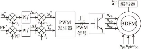
图14 典型的无刷双馈发电机闭环标量控制系统Fig.14 Typical closed-loop scalar control system of BDFM
3.2矢量控制
文献[66]在对有刷双馈发电机有功和无功功率控制研究的基础上,提出了针对CDFIG的定子磁链定向控制(Stator-Flux-Oriented Control,SFOC),实现了与有刷双馈发电机相似的有功、无功功率解耦控制,如图15所示。其中,控制绕组的d轴电流分量用于控制功率绕组无功功率,q轴分量用于控制功率绕组有功功率(或速度),使用前馈控制对转子电阻引起的d、q轴交叉耦合进行补偿。类似的分析与控制也见于文献[67,68]。文献[69,70]将该定子磁链定向控制应用于NLR-BDFIG,不同之处在于,文献[69]采用三级PI控制器,而文献[70]针对电机本身的特性对控制器结构进行适当简化,采用单级PI控制器实现了转速和无功功率的解耦控制,显示出其在风力发电应用中的广阔前景。相似的控制结构也被用于控制BDFRG[71-73]。
3.3直接转矩控制
文献[74]首次提出了NLR-BDFIG的预测直接转矩控制(Direct Torque Control,DTC)。由于假设两套定子绕组磁通保持不变,动态响应和控制精度受到一定程度的限制。而且,所有的控制变量均定向在转子坐标系而非通常感应电机中所采用的静止坐标系,因而需要旋转坐标变换。文献[75]建立了一种基于电压空间矢量表的经典DTC控制策略,控制方式具有恒定的开关频率。但在单变量控制情形下,转矩与控制绕组磁通不能得到同时控制。文献[76]对NLR-BDFIG的DTC进行改进,首次将间接定子量控制(Indirect Stator-Quantities Control,ISC)应用于无刷双馈发电机,大大降低了控制算法对电机参数的依赖程度,只需要两套定子绕组电阻。由于不需要旋转坐标变换,控制结构大大简化。该方法还被进一步用于转速(有功)与无功的同时控制[77]。

图15 级联式无刷双馈发电机定子磁链定向控制Fig.15 Stator flux oriented control of CDFIM
3.4非线性控制
无刷双馈发电机具有复杂的动态模型,尽管通过前馈补偿或电机本身控制特性的改善可以实现有限转速范围内有功和无功的近似解耦控制,但仍不能获得令人满意的控制效果,特别是当电机运行转速接近功率绕组自然同步转速时。许多研究人员尝试将先进的非线性控制方法应用于无刷双馈发电机,如滑模控制(Sliding Mode Control,SMC)[78-80]、反馈线性化控制(Feedback Linearization,FBL)[47,81]。
3.5无刷双馈发电机的统一控制
从控制角度来看,现有技术均为对某一类无刷双馈发电机进行独立控制,未对不同无刷双馈发电机在控制上的相似性进行深入分析。事实上,三种主要无刷双馈发电机的数学模型可统一表示为
(6)
(7)
(8)
式中,γ为常系数;F(·)为统一模型表述而引入的算子符号。电磁转矩可统一表示为
(9)
不同无刷双馈发电机的数学模型可通过不同的参数取值而得到,见表2。

表2 不同无刷双馈发电机对应的统一模型参数取值Tab.2 Parameters for the unified model of different BDFMs
因此,从控制角度来讲,三种主要无刷双馈发电机结构可实现统一控制。BDFRG是CDFIG和NLR-BDFIG控制的特例(令rr=0即可)。或者说,CDFIG和NLR-BDFIG如果转子电阻相对较小可忽略时,则可使用BDFRG的控制方法进行控制。
4 新型双定子无刷双馈风力发电机
综上分析可知,尽管针对无刷双馈发电机的研究由来已久,但无刷双馈发电机至今未能成功商业化并取代现有有刷双馈发电机。究其原因主要有以下几个方面:①相比于有刷双馈发电机,现有无刷双馈发电机的转矩密度和功率密度偏低;②相比于有刷双馈发电机,无刷双馈发电机的无功管理复杂;③磁场调制式无刷双馈发电机的网侧电压电流谐波含量偏高;④CDFIG 和NLR-BDFIG的控制精度具有转速依赖性。
基于三种主要无刷双馈发电机转矩密度和功率密度的比较分析,为提高转矩密度,同时缩短电机轴向长度,文献[82]提出一种新型双定子无刷双馈风力发电机。如图16所示,该新型电机结构包含同轴布置的内外两个定子和位于两个定子之间的杯形转子。定转子上共设置四套分布绕组,且转子内外层绕组之间反相序连接形成“和级联”。
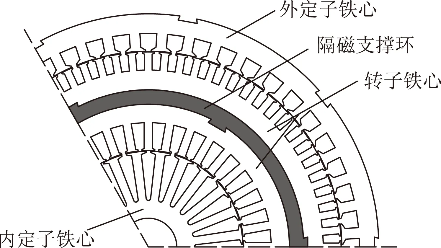
图16 新型双定子无刷双馈风力发电机截面图Fig.16 Cross-section of the proposed dual-stator BDFM
4.1转速关系
为满足双馈同步运行,转子机械转速与功率绕组PW和控制绕组CW供电频率之间满足式(1)。如图17所示,双定子无刷双馈风力发电机类似于一个“电气差速器”,位于内外定子之间的转子(机械转速为ωr)协调外气隙与内气隙一快一慢两个旋转磁场(转速分别为ωp/pp和ωc/pc)。

图17 双定子无刷双馈风力发电机转速关系Fig.17 Speed relationship of dual-stator BDFM
4.2工作模式
由于新型双定子无刷双馈风力发电机具有两个电气端口,既可以单馈,也可以双馈运行。按照供电方式的不同,共有4种可能的工作模式,分别为简单异步模式、级联异步模式、双馈同步模式和双馈异步模式[55]。4种工作模式的存在条件以及转矩构成见表3。4种工作模式对应的转矩能力如图18所示。
图18a给出了简单异步模式与级联异步模式下的转矩转速特性,同时给出了单台感应电机的转矩转速曲线作为参照。其中,简单异步模式产生的转矩几乎为零,而级联异步模式下能够产生与单台感应电机相当的转矩水平。
图18b给出了双馈同步模式下的转矩转速范围。在不考虑饱和与稳态温升的理想情况下,双定子无刷双馈风力发电机可获得最大的转矩转速运行范围,如图18b理想上限与理想下限所包围的面域所示;当控制绕组采用恒压频比控制方式供电时,运行范围缩小至恒压频比上限与恒压频比下限所包围的面域;如果进一步考虑各绕组电流不超过额定值,双馈同步运行范围如图18b中有效上限与有效下限所包围的面域所示。可见当功率绕组极对数等于控制绕组极对数时,双定子无刷双馈风力发电机可在0~1.8倍自然同步转速范围内实现恒转矩运行。

表3 新型双定子无刷双馈风力发电机工作模式Tab.3 Operation modes of dual-stator BDFM
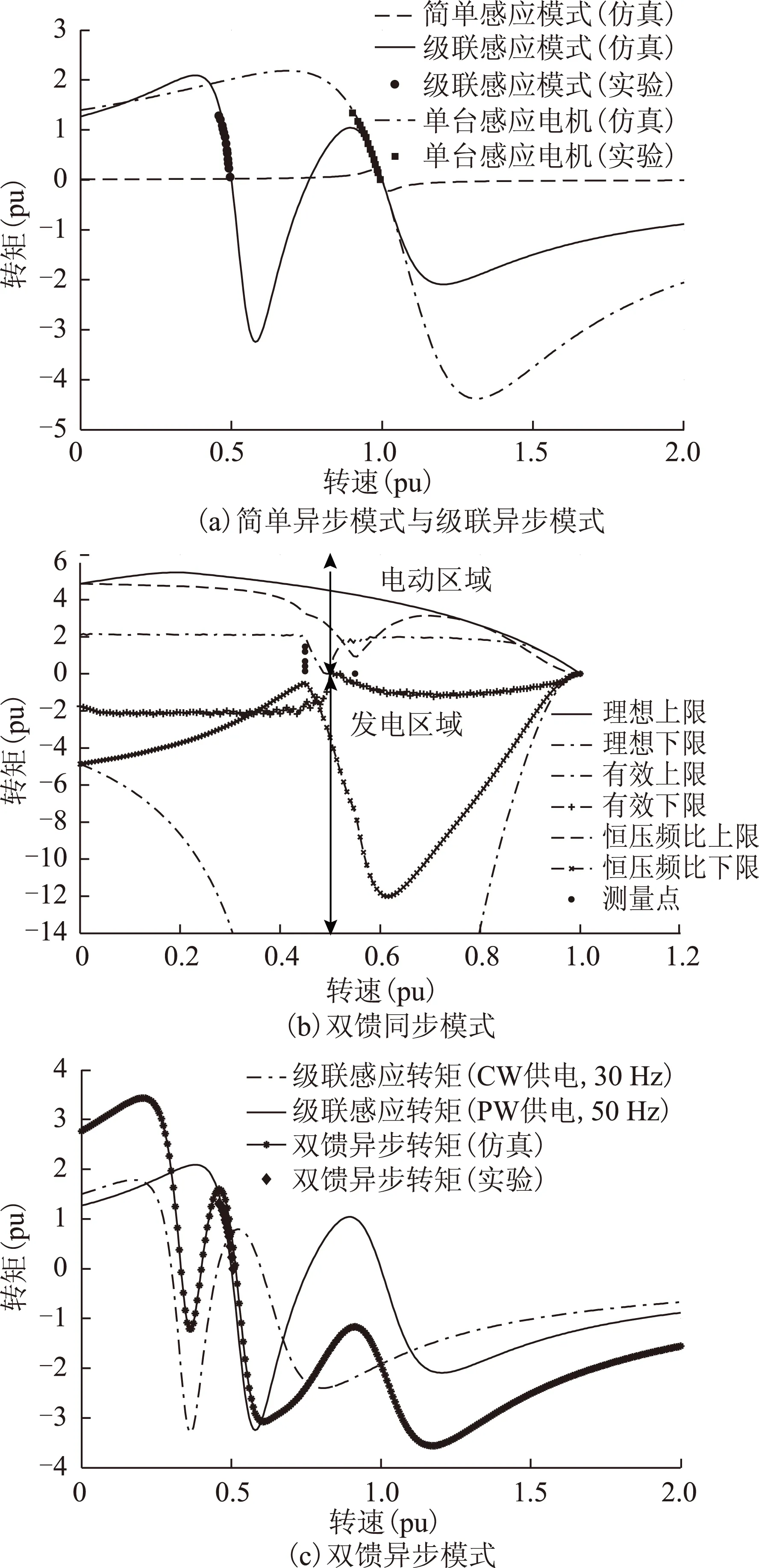
图18 新型双定子无刷双馈风力发电机转矩-转速特性Fig.18 Torque-speed characteristics of dual-stator BDFM
双馈异步模式下的转矩转速曲线如图18c所示。可以看到,双馈异步模式下的转矩转速曲线是由两条级联异步转矩转速曲线通过简单叠加形成的。
由图18可见,4种工作模式均可用于发电。其中,三种异步工作模式下的发电运行特性类似于异步发电机,而双馈同步运行模式可在宽调速范围内变速恒频,同时保持恒定转矩。因而风力发电应用场合更期望电机运行在双馈同步模式下。
4.3功率关系
忽略电机铜耗,可以分析得到双定子无刷双馈风力发电机在不同转速区间发电运行的功率流。其中,超自然同步速发电模式的功率流如图19所示。不同发电模式下的功率流向如图20所示。
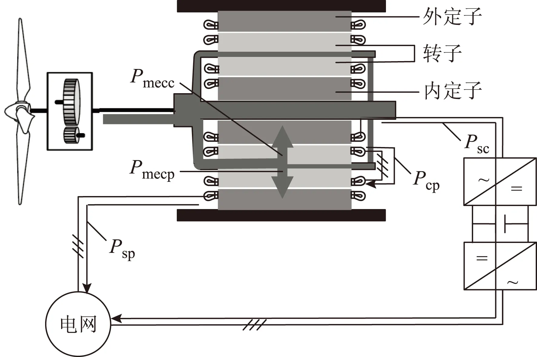
图19 双定子无刷双馈风力发电机功率流(超自然同步速发电)Fig.19 Power flow of dual-stator BDFM for super natural synchronous speed

图20 不同转速下的功率流向Fig.20 Power flow under different speeds
4.4设计方法
新型双定子无刷双馈风力发电机可以按照实际需要设计为电动机或发电机,其设计流程如图21所示[82]。

图21 双定子无刷双馈风力发电机设计流程Fig.21 Design flow chart of dual-stator BDFM
基于该设计流程,设计并加工了一台7.5 kW新型双定子无刷双馈风力发电机样机,如图22所示。
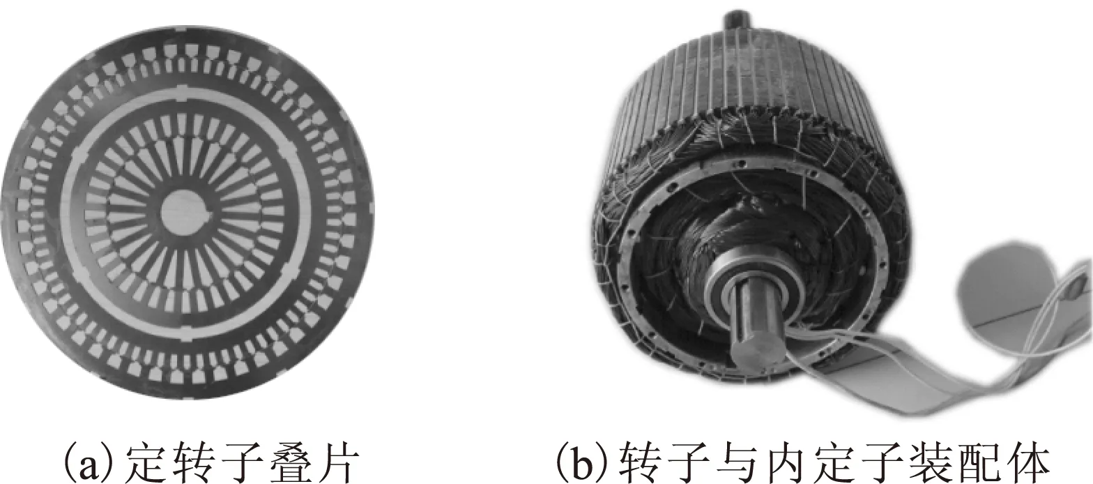
图22 7.5 kW双定子无刷双馈风力发电机样机Fig.22 Prototype of 7.5kW dual-stator BDFM
对样机的级联异步特性和双馈同步特性进行了仿真与实验测试,部分结果如图23和图24所示。实验结果与仿真分析非常吻合。


图23 级联异步模式转矩-转速特性Fig.23 Cascaded asynchronous characteristics

图24 空载励磁特性Fig.24 Excitation characteristic at no-load
4.5独立运行发电控制
当双定子无刷双馈风力发电机独立发电运行时,要求输出满足电能质量要求的电能。控制目标为输出电压的幅值和频率,典型的控制框图如图25所示[83]。采用所提出的直接电压控制方法,可以产生令人满意的输出电压。实验与仿真波形非常吻合,如图26所示。
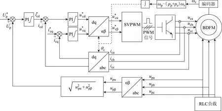
图25 双定子无刷双馈风力发电机独立发电运行控制Fig.25 Stand-alone operation of dual-stator BDFG
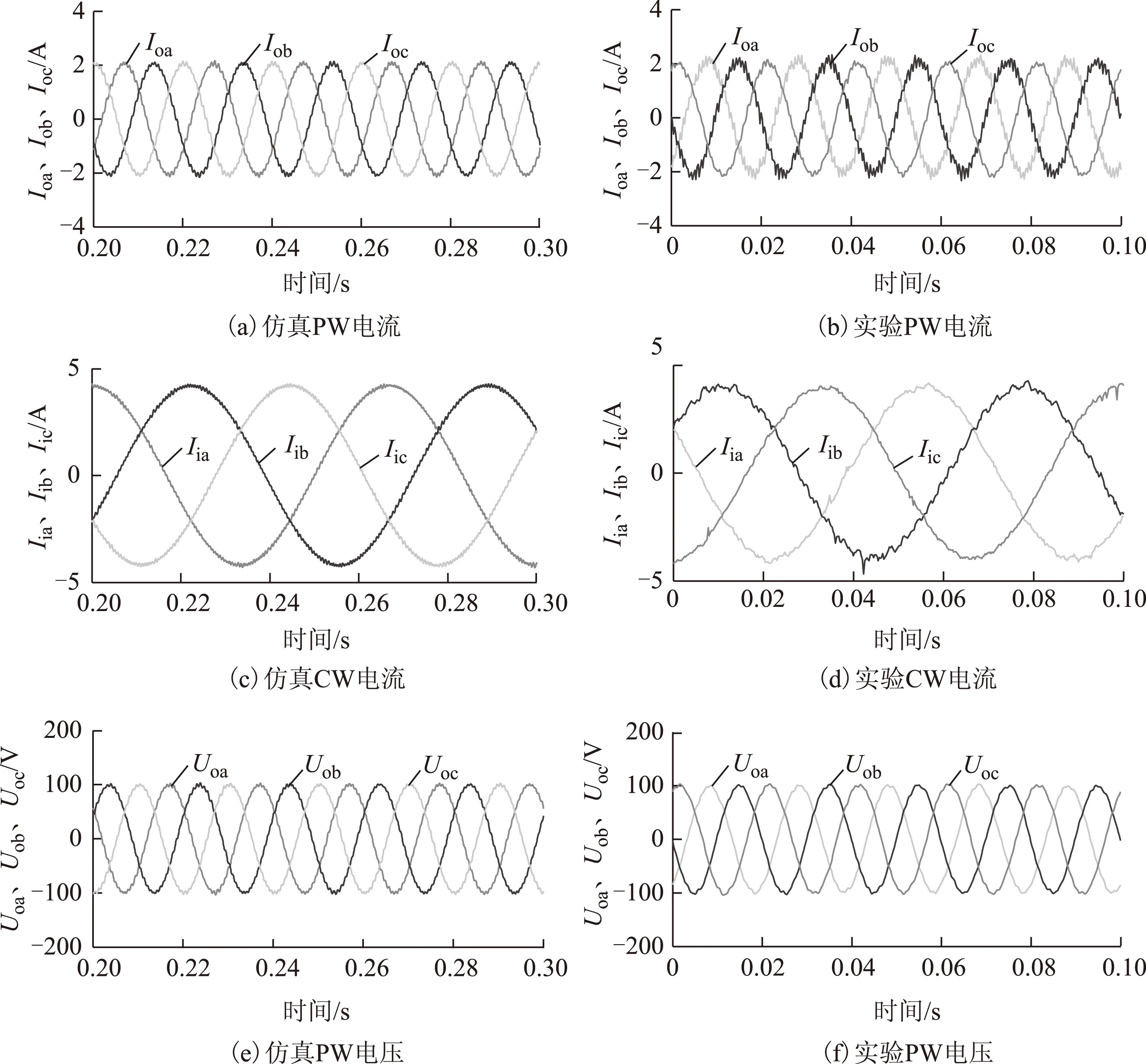
图26 双定子无刷双馈风力发电独立运行波形Fig.26 Waveforms of stand-alone operation of dual-stator BDFG
4.6并网运行发电控制
当双定子无刷双馈风力发电机并网发电运行时,要求发电机具备:①有功和无功调节能力;②不对称运行
能力;③低电压穿越能力。典型的并网运行发电控制系统如图27所示[84]。采用所提出的并网运行控制策略可实现有功和无功的解耦控制,实验波形如图28所示。

图27 双定子无刷双馈风力发电机并网运行控制Fig.27 Grid-connected operation of dual-stator BDFG

图28 双定子无刷双馈风力发电机并网运行实验波形Fig.28 Experimental waveforms of grid-connected operation of dual-stator BDFG
5 无刷双馈发电机的应用前景与发展趋势
本文通过对多种无刷双馈发电机深入比较分析后发现,无刷双馈发电机适合设计为多极对数的中低速发电机,以改善转矩密度和整体效率。目前已有多个大型无刷双馈发电机试运行的案例,如剑桥大学与风能科技公司合作研究的250 kW NLR-BDFIG等。
相比于现有结构,新型双定子无刷双馈风力发电机在转矩密度和电能质量方面具有明显优势,因而成为最有潜力取代现有有刷双馈发电机的一种无刷双馈发电机。
由于双定子无刷双馈风力发电机通过保留异步转矩分量以增加转矩密度,而现有的控制策略大多忽略异步转矩分量的影响而将CDFIG作为一台工作于自然同步转速附近的交流同步发电机进行控制,因而后续工作将致力于考虑异步转矩分量后双定子无刷双馈风力发电机的连续控制。
[1]Global Wind Energy Council,Global wind report 2013.[EB/OL].http://www.gwec.net/publications/global-wind-report-2/.
[2]Global Wind Energy Council,Offshore wind policy and market assessment-a global outlook[EB/OL].http://www.gwec.net/publications/topical-report/.
[3]Cheng Ming,Zhu Ying.The state of the art of wind energy conversion systems and technologies:a review[J].Energy Conversion and Management,2014,88:332-347.
[4]Zhu Ying,Cheng Ming,Hua Wei,et al.A novel maximum power point tracking control for permanent magnet direct drive wind energy conversion systems[J].Energies,2012,5(12):1398-1412.
[5]高剑,黄守道,张文娟,等.基于变流器控制策略的直驱永磁风力发电机优化设计[J].电工技术学报,2013,28(7):103-109.
Gao Jian,Huang Shoudao,Zhang Wenjuan,et al.Optimal design for permanent magnet wind power generators based on converter controlling algorithm[J].Transactions of China Electrotechnical Society,2013,28(7):103-109.
[6]李祥林,程明,邹国棠,等.聚磁式场调制永磁风力发电机工作原理与静态特性[J].电工技术学报,2014,29(11):1-9.
Li Xianglin,Cheng Ming,Zou Guotang,et al.Principle and analysis of a new flux-concentrating field-modulated permanent-magnet wind power generator[J].Transactions of China Electrotechnical Society,2014,29(11):1-9.
[7]Li Xianglin,Chau K T,Cheng Ming.Analysis,design and experimental verification of a field-modulated permanent-magnet machine for direct-drive wind turbines[J].IET Electric Power Applications,2015,9(2):150-159.
[8]Boldea I,Tutelea L,Blaabjerg F.High power wind generator designs with less or no PMs:an overview[C]//2014 17th International Conference on Electrical Machines and Systems (ICEMS),Hangzhou,2014:1-14.
[9]Hunt L J.A new type of induction motor[J]. Journal of the Institution of Electrical Engineers,1907,39(186):648-667.
[10]Smith B H.Synchronous behavior of doubly fed twin stator induction machine[J].IEEE Transactions on Power Apparatus and Systems,1967,PAS-86(10):1227-1236.
[11]Ruviaro M,Runcos F,Sadowski N,et al.Analysis and tests results of a brushless doubly-fed induction machine with rotary transformer[J].IEEE Transaction on Industrial Electronics,2012,59(6):2670-2677.
[12]Malik Naveed ur Rehman,Sadarangani C.Brushless doubly-fed induction machine with rotating power electronic converter for power applications[C]//International Conference on Electrical Machines and Systems (ICEMS),Beijing,2011:1-6.
[13]Broadway A R W,Burbridge L.Self-cascaded machine:a low speed motor or high frequency brushless alternator[J].Proceedings of the Institution of Electrical Engineers,1970,117(7):1277-1290.
[14]Xiong Fei,Wang Xuefan.Design of a low-harmonic-content wound rotor for the brushless doubly fed generator[J].IEEE Transactions on Energy Conversion,2014,29(1):158-168.
[15]Broadway A R W.Cageless induction machine[J].Proceedings of the Institution of Electrical Engineers,1971,118(11):1593-1600.
[16]Zhang Fengge,Li Yongxin,Wang Xiuping.The design and FEA of brushless doubly-fed machine with hybrid rotor[C]//International Conference on Applied Superconductivity and Electromagnetic Devices,Chengdu,2009:324-327.
[17]Hopfensperger B,Atkinson D J,Lakin R A.Steady state of the cascaded doubly-fed induction machine[J].European Transactions on Electrical Power,2002,12(6):427-437.
[18]Malik Naveed ur Rehman,Sadarangani C.Behavior of a brushless doubly-fed induction generator with a rotating power electronic converter during symmetrical voltage sags[C]//2012 XXth International Conference on Electrical Machines(ICEM),Marseille,2012:865-871.
[19]Malik Naveed ur Rehman,Sadarangani C.Extended vector control of a rotating power electronic brushless doubly-fed induction generator under unsymmetrical voltage sags[C]//38th Annual Conference on IEEE Industrial Electronics Society,Montreal,QC,2012:1793-1798.
[20]Roberts P C,Long T,Mcmahon R A,et al.Dynamic modelling of the brushless doubly fed machine[J].IET Proceedings-Electric Power Applications,2013,7(7):544-556.
[21]Williamson S,Boger M S.Impact of inter-bar currents on the performance of the brushless doubly fed motor[J].IEEE Transactions on Industry Applications,1999,35(2):453-460.
[22]Kem P A,Boger M,Wiedenbrug E,et al.Investigation of rotor current distribution in brushless doubly-fed machines[C]//Conference Record of the 1996 IEEE Industry Applications Conference,Thirty-First IAS Annual Meeting, San Diego,CA,1996,1:638-643.
[23]Alexander G C.Characterization of the brushless,doubly-fed machine by magnetic field analysis[C]//Conference Record of the 1990 IEEE Industry Applications Society Annual Meeting,Seattle,WA,USA,1990,1:67-74.
[24]Chen Jiansheng,Zhang Wei.Harmonics in brushless doubly fed induction generator for torque ripple analysis and modeling[J].IEEE Transactions on Magnetics,2014,50(11):1-4.
[25]Logan T,Mcmahon R A,Seffen K.Noise and vibration in brushless doubly fed machine and brushless doubly fed reluctance machine[J]. IET Electric Power Applications,2014,8(2):50-59.
[26]Gorginpour H,Oraee H,Abdi E.Calculation of core and stray load losses in brushless doubly fed induction generators[J].IEEE Transactions on Industrial Electronics,2014,61(7):3167-3177.
[27]Abdi E,Malliband P,Mcmahon R A.Study of iron saturation in brushless doubly-fed induction generators[C]//2010 IEEE Energy Conversion Congress and Exposition,Atlanta,GA,2010:3501-3508.
[28]Mcmahon R A,Roberts P C,Wang X,et al.Performance of BDFM as generator and motor[J].IEE Proceedings-Electric Power Applications,2006,153(2):289-299.
[29]Gorginpour H,Jandaghi B,Oraee H.A novel rotor configuration for brushless doubly-fed induction generators[J].IET Electric Power Applications,2013,7(2):106-115.
[30]Liao Y,Xu L,Zhen L.Design of a doubly fed reluctance motor for adjustable-speed drives[J].IEEE Transactions on Industry Applications,1996,32(5):1195-1203.
[31]Xu L,Liang F,Lipo T A.Transient model of a doubly excited reluctance motor[J].IEEE Transactions on Energy Conversion,1991,6(1):126-133.
[32]Fukami T,Momiyama M,Shima K.Steady-state analysis of a dual-winding reluctance generator with a multiple-barrier rotor[J].IEEE Transactions on Energy Conversion,2008,23(2):492-498.
[33]Xu Longya,Tang Yifan,Ye Lurong.Comparison study of rotor structures of doubly excited brushless reluctance machine by finite element analysis[J].IEEE Transactions on Energy Conversion,1994,9(1):165-172.
[34]Xu Longya,Wang Fengxiang.Comparative study of magnetic coupling for a doubly fed brushless machine with reluctance and cage rotors[C]//Conference Records of the 1997 IEEE Industry Applications Conference,Thirty-Second IAS Annual Meeting, New Orleans,LA,1997,1:326-332.
[35]Scian I,Dorrell D G,Holik P J.Assessment of losses in a brushless doubly-fed reluctance machine[J].IEEE Transactions on Magnetics,2006,42(10):3425-3427.
[36]Chilakapati N,Ramsden V S,Ramaswamy V,et al.Investigation of doubly fed twin stator induction motor as a variable speed drive[C]//1998 International Conference on Power Electronic Drives and Energy Systems for Industrial Growth,Perth,1998,1:160-165.
[37]Basic D,Zhu Jianguo,Boardman G.Modeling and steady-state performance analysis of a brushless doubly fed twin stator induction generator[C]//Australasian Power Engineering Conference (AUPEC),Melbourne,2002.
[38]Williamson S,Ferreria A,Wallace A.Generalised theory of the brushless doubly-fed machine.part 1:analysis[J].IEE Proceedings-Electric Power Applications,1997,144(2):111-121.
[39]Williamson S,Ferreira A.Generalized theory of the brushless doubly-fed machine.part 2:model verification and performance[J].IEE Proceedings-Electric Power Applications,1997,144(2):123-129.
[40]Roberts P C,Mcmahon R A,Tavner P J,et al.Equivalent circuit for the brushless doubly fed machine (BDFM) including parameter estimation and experimental verification[J].IEE Electric Power Applications,2005,152(4):933-942.
[41]Hashemnia M,Tahami F,Tavner P,et al.Steady-state analysis and performance of a brushless doubly fed machine accounting for core loss[J].IET Electric Power Applications,2013,7(3):170-178.
[42]Hashemnia M,Tahami F,Oyarbide E.Investigation of core loss effect on steady-state characteristics of inverter fed brushless doubly fed machines[J].IEEE Transactions on Energy Conversion,2014,29(1):57-64.
[43]Gorginpour H,Oraee H,Mcmahon R A.Performance description of brushless doubly-fed induction machine in its asynchronous and variable speed synchronous modes[J].Journal of Electromagnetic Analysis and Applications,2011,3(12):490-511.
[44]Ferreira A C,Williamson S.Time-stepping finite-element analysis of brushless doubly fed machine taking iron loss and saturation into account[J].IEEE Transactions on Industry Applications,1999,35(3):583-588.
[45]Hsu Y C,Hsieh M F,Mcmahon R A.A general design method for electric machines using magnetic circuit model considering the flux saturation problem[C]//International Conference on Power Electronics and Drive Systems (PEDS),Taipei,2009:625-630.
[46]Hsieh M F,Lin I H,Hsu Y C,et al.Design of brushless doubly-fed machines based on magnetic circuit modeling[J].IEEE Transactions on Magnetics,2012,48(11):3017-3020.
[47]Roberts P C.A study of brushless doubly-fed(induction)machines[D].UK:University of Cambridge,2004.
[48]Li R,Wallace A,Spee R,et al.Two-axis model development of cage rotor brushless doubly-fed machines[J].IEEE Transactions on Energy Conversion,1991,6(3):453-460.
[49]Li R,Wallace A,Spee R.Dynamic simulation of brushless doubly-fed machines[J].IEEE Transactions on Energy Conversion,1991,6(3):445-452.
[50]Liang Feng,Xu Longya,Lipo T A.d-q analysis of a variable speed doubly AC excited reluctance motor[J].Electric Machines & Power Systems,1991,19(2):125-138.
[51]Malik N R,Sadarangani C.Dynamic modeling and control of a brushless doubly-fed induction generator with a rotating power electronic converter[C]//2012 XXth International Conference on Electrical Machines,Marseille,2012:900-906.
[52]Poza J,Oyarbide E,Roye D,et al.Unified reference frame d-q model of the brushless doubly-fed machine[J].IET Proceedings-Electric Power Applications,2006,153(5):726-734.
[53]Barati F,Shao Shiyi,Abdi E,et al.Generalized vector model for the brushless doubly-fed machine with a nested-loop rotor[J].IEEE Transactions on Industrial Electronics,2011,58(6):2313-2321.
[54]Betz R E,Jovanovic M G.Introduction to the space vector modelling of the brushless doubly-fed reluctance machine[J].Electric Power Components and Systems,2003,31(8):729-755.
[55]Han Peng,Cheng Ming,Wei Xinchi,et al.Modeling and performance analysis of a dual-stator brushless doubly fed induction machine based on spiral vector theory[J].IEEE Transactions on Industry Applications,2016,52(2):1380-1389.
[56]Gorginpour H,Oraee H,Mcmahon R.A novel modeling approach for design studies of brushless doubly fed induction generator based on magnetic equivalent circuit[J].IEEE Transactions on Energy Conversion,2013,28(4):902-912.
[57]Gorginpour H,Oraee H,Mcmahon R A.Electromagnetic-thermal design optimization of the brushless doubly fed induction generator[J].IEEE Transactions on Industrial Electronics,2014,61(4):1710-1721.
[58]Dorrell D G.Design requirements for doubly-fed reluctance generators[C]//2007 7th International Conference on Power Electronics and Drive Systems,Bangkok,2007:981-988.
[59]Knight A M,Betz R E,Dorrell D G.Design principles for brushless doubly fed reluctance machines[C]//37th Annual Conference on IEEE Industrial Electronics Society,Melbourne,VIC,2011:3602-3607.
[60]Knight A M,Betz R E,Song W K,et al.Brushless doubly-fed reluctance machine rotor design[C]//2012 IEEE Energy Conversion Congress and Exposition (ECCE),Raleigh,NC,2012:2308-2315.
[61]Knight A M,Betz R E,Dorrell D G.Design and analysis of brushless doubly fed reluctance machines[J].IEEE Transactions on Industry Applications,2013,49(1):50-58.
[62]Zhou D,Spee R,Wallace A K.Laboratory control implementation for doubly fed machines[C]//International Conference on Industrial Electronics,Control,and Instrumentation,Maui,HI,1993,2:1181-1186.
[63]Spee R,Bhowmik S,Enslin J H R.Adaptive control strategies for variable-speed doubly-fed wind power generation systems[C]//Conference Record of the 1994 IEEE Industry Applications Society Annual Meeting,Denver,CO,1994,1:545-552.
[64]Brune C S,Spee R,Wallace A K.Experimental evaluation of a variable-speed,doubly-fed wind power generation system[J].IEEE Transactions on Industry Applications,1994,30(3):648-655.
[65]Huang Shoudao,Wei Yan,Lin Youjie,et al.Fuzzy-based power factor control for brushless doubly-fed machines[C]//Proceedings of the 4th World Congress on Intelligent Control and Automation,Shanghai,2002,1:587-591.
[66]Hopfensperger B,Atkinson D J,Lakin R A.Stator flux oriented control of a cascaded doubly-fed induction machine[J].IEE Proceedings-Electric Power Applications,1999,146(6):597-605.
[67]Basic D,Zhu Jianguo,Boardman G.Transient performance study of a brushless doubly fed twin stator induction generator[J].IEEE Transactions on Energy Conversion,2003,18(3):400-408.
[68]Protsenko K,Xu Dewei.Modeling and control of brushless doubly fed induction generators in wind energy applications[J].IEEE Transactions on Power Electronics,2008,23(3):1191-1197.
[69]Shao Shiyi,Abdi E,Barati F,et al.Stator-flux-oriented vector control for brushless doubly fed induction generator[J].IEEE Transactions on Industrial Electronics,2009,56(10):4220-4228.
[70]Poza J,Oyarbide E,Sarasola I,et al.Vector control design and experimental evaluation for the brushless doubly fed machine[J].IET Proceedings-Electric Power Applications,2009,3(4):247-256.
[71]Tang Yifan,Xu Longya.Vector control and fuzzy logic control of doubly fed variable speed drives with DSP implementations[J].IEEE Transactions on Energy Conversion,1995,10(4):661-668.
[72]Ademi S,Jovanovic M G.Vector control methods for brushless doubly fed reluctance machines[J].IEEE Transactions on Industrial Electronics,2015,62(1):96-104.
[73]Ademi S,Jovanovic M G,Hasan M.Control of brushless doubly-fed reluctance generators for wind energy conversion systems[J].IEEE Transactions on Energy Conversion,2015,30(2):596-604.
[74]Brassfield W R,Spee R,Habetler T G.Direct torque control for brushless doubly-fed machines[J].IEEE Transactions on Industry Applications,1996,32(5):1098-1104.
[75]Sarasola I,Poza J,Rodriguez M A,et al.Direct torque control design and experimental evaluation for the brushless doubly fed machine[J].Energy Conversion and Management,2011,52(2):1226-1234.
[76]Zhang Ailing,Wang Xin,Jia Wenxia,et al.Indirect stator-quantities control for the brushless doubly fed induction machine[J].IEEE Transactions on Power Electronics,2014,29(3):1392-1401.
[77]Zhao Rongli,Zhang Ailing,Ma Yun,et al.The dynamic control of reactive power for the brushless doubly fed induction machine with indirect stator-quantities control scheme[J].IEEE Transactions on Power Electronics,2015,30(9):5046-5057.
[78]Wang Xiaoyuan,Yang Jinming,Zhang Xianyong,et al.Sliding mode control of active and reactive power for brushless doubly-fed machine[C]//International Colloquium on Computing,Communication,Control and Management,Guangzhou,2008,2:294-298.
[79]Valenciaga F.Active and reactive power control of a brushless doubly fed reluctance machine using high order sliding modes[C]//18th International Conference on Electrical Machines (ICEM),Vilamoura,2008:1-6.
[80]Valenciaga F,Puleston P F.Variable structure control of a wind energy conversion system based on a brushless doubly fed reluctance generator[J].IEEE Transactions on Energy Conversion,2007,22(2):499-506.
[81]Roberts P C,Maciejowski J M,Mcmahon R A,et al.A simple rotor current observer with an arbitrary rate of convergence for the brushless doubly-fed (induction) machine (BDFM)[C]//Proceedings of the 2004 IEEE International Conference Control Applications,Taipei,Taiwan,2004,1:266-271.
[82]Han P,Cheng M,Luo R.Design and analysis of a brushless doubly-fed induction machine with dual-stator structure[J].IEEE Transactions on Energy Conversion,2016,DOI:10.1109/TEC.2016.2547955.
[83]Wei Xinchi,Cheng Ming,Wang Wei,et al.Direct voltage control of dual-stator brushless doubly-fed induction generator for stand-alone wind energy conversion systems[J].IEEE Transactions on Magnetics,2016,52(7):8203804.
[84]Cheng Ming,Wei Xinchi,Han Peng,et al.Modeling and control of a novel dual-stator brushless doubly-fed wind power generation system[C]//2014 17th International Conference on Electrical Machines and Systems (ICEMS),Hangzhou,2014:3029-3035.
Design,Analysis and Control of Brushless Doubly-Fed Generators for Wind Power Application
Cheng MingHan PengWei Xinchi
(School of Electrical EngineeringSoutheast UniversityNanjing210096China)
The brushless doubly-fed machine (BDFM) is a new type of electrical machines with two AC electrical ports and a common mechanical port.It inherently possesses the variable speed constant frequency (VSCF) capability.It has already been widely recognized as the most promising candidate for replacing the slip-ring doubly-fed induction generator (DFIG) for its distinct advantages such as high reliability and reduced maintenance cost due to the elimination of brushes and approximate decoupled control of active and reactive power. This paper introduces the machine topologies and operating principles of a vast variety of existing BDFMs with the similarities,differences and challenges in current research summarized,compares the torque/power density from the perspective of machine design,and overviews the analysis design methods and control strategies,with the internal consistency of control of different BDFMs discussed. Based on the design,modeling,and control of BDFM,a novel dual-stator brushless doubly-fed induction machine is proposed,analyzed,and controlled for stand-alone as well as grid-connected power generation with experimental validation.Finally,the potential applications and future trends of BDFMs are discussed.
Brushless doubly-fed machines,wind power generation,control strategy,design and analysis method,intrinsic consistency,power density,torque density
国家自然科学基金(51320105002)和中达学者基金资助项目。
2016-06-29改稿日期2016-08-02
TM315
程明男,1960年生,博士,教授,博士生导师,IEEE Fellow,IET Fellow,研究方向为电机与控制、电动汽车及其驱动系统、新能源发电技术等。
E-mail:mcheng@seu.edu.cn (通信作者)
韩鹏男,1989年生,博士研究生,研究方向为无刷双馈电机的设计、分析与控制。
E-mail:hanpeng360001@163.com