基于五束光的三维多普勒测振仪设计
2016-11-07张深逢宋云峰
郭 华,张深逢,陈 康,宋云峰,叶 岗
(宁波舜宇智能测量仪器有限公司,浙江 余姚 315400)
基于五束光的三维多普勒测振仪设计
郭华,张深逢,陈康,宋云峰,叶岗
(宁波舜宇智能测量仪器有限公司,浙江 余姚315400)
为了实现物体的三维振动分析测量,设计了一种基于五束激光的多普勒振动测量系统。该系统将五束激光汇聚到一个焦点,并照射到被反射膜覆盖的被测物体表面,经过反射后,散射光被光电二极管接收,并进入高精度信号处理系统,分别得到五路振动信息,通过计算机处理后,可以分别解析得到包括频率和振幅的三维振动信息。实验结果表明,该系统有望被应用于高精度的无接触振动测量。
激光多普勒测振仪; 三维振动测量; 五束激光
Introduction
As an established vibration measurement technology,laser Doppler vibrometer (LDV) has been widely applied to measure area vibration mode shapes[1],detect shear wave in ultrasonic range[2],and measure mode shapes of structures and machine components[3].Especially,with the development of scanning laser Doppler vibrometer (SLDV),full-field measurement can also be supplied as a high-speed camera based laser interferometry[4-7].However,both the single-point LDV and SLDV can only supply the beam direction vibration.In order to get 3-D vibration information,the target has to be illuminated by three laser beams inx,yandzaxis direction respectively,or the vibrometer microscope with a single-impinging laser beam,which collects scattered lights from at least three directions[8].All these systems are complicated and lacking of stability.In this paper,we present the 3-D laser Doppler vibrometer system using five laser beams which can supply 3-D vibration information in real time.
1 Measurement principle
The system using five laser beams is designed for measuring 3-D vibration information of objects.Five laser beams are focalized on one spot to illuminate vibrating target,and the photo-detectors are placed at the same location as lasers to collect reflected scattering lights.A convex lens is placed in front of lasers to focus the laser beams on the point,and Fig.1(a) represents a cross section of the system.The measurement of beam direction (zaxis) which shares the same principle with signal-point LDV can achieve vibration information by processing the reflected scattering lights inzaxis.The vibration information ofzaxisVzcan be achieved by demodulating the interference signals (vibration measurement module 2 in Fig.1 (a)) which are produced by the source beam (beam 2 in Fig.1 (b)) and its reflected scattering beam.The principle of measurement ofx-yplane is much more complicated.We will takexaxis as an example.Three vibration measurement modules are placed inxaxis direction orderly as shown in Fig.1(a),and module 2 is equidistant from module 1 and module 3.The angleθis about 30 degree.All the three beams are focalized on a point (focus point in Fig.1 (a)) of the irradiating surface,which is covered by a piece of reflective strip.The vibration measurement module 1 will demodulate the interference signals of beam 1 and its reflected scattering beam to get vibration informationV1,which mix the components ofxaxisVxandzaxisVz.The reference can be described by
(1)
where θ is the angle of beam 1 and beam 3.Similarly,module 3 can get the same result
(2)
According to (1) and (2),the angel of beam 1 and beam 3 can be calculated by
(3)
Finally,vibration information ofxaxis can be achieved by
(4)
Similarly,we can get vibration information iny-zplane based on beam 2,beam 4 and beam 5 in Fig.1 (b).Finally,3-D vibration information will be achieved inx,yandzaxis based on the five beams.

Fig.1 System schematic diagram
In fact,when angleθis known as a constant,there would only need beam 1,2 and 4 to achieve 3-D vibration information.The design using five beams is based on two considerations.For one hand,the angleθcan be calibrated dynamically in the process of experiments to supply precision measurement.For the other hand,as a following work,the system would be upgraded to supply 3-D full-field measurement by scanning targets,and thenθwould not be a constant.
2 System description
In order to enhance stability and guarantee the precision of measurement,the experimental system is established by five commercial signal-point LDVs (Sunny Advanced Instruments,LV-S01),which are distributed inx-yplane as shown in Fig.1(b),and Fig.2(b) shows the photography of the system setup.One of them (beam 2) is placed in the center,and the other four beams are symmetrical and fixed in the plane.The distance between LDVs (h in Fig.1(a)) is about 267 mm.The angle θ of beam 1 and beam 3 is 30 degree and the distance (f in Fig.1(a)) between LDV and focus point is 500 mm.Fig.2(a) shows the optical setup of signal-point LDV which supply vibration measurement inzaxis.A shaker system (Far East Vibration Tech,JX-3B) is placed in front of the system (focus point in Fig.1(a)) as a vibration source,whose irradiated surface is covered by a piece of reflective strip.So each LDV would collect its own reflected scattering light in any direction,and all of them will work independently without cross-talk.The reflected scattering lights are collected by high-sensitivity photo-detectors and then processed by high-speed demodulation circuit.Five vibration signals are digitized by a high-speed A-D card (NI,USB-6366) and saved in the PC with a sampling rate of 100 kHz after demodulation.Then we can get the 3-D vibration information respectively inx,yandzaxis by the PC according to the self-designed algorithm based on equation(4).As a result,frequency and amplitude of the target in three dimensions can be achieved in real time.
3 Experimental results
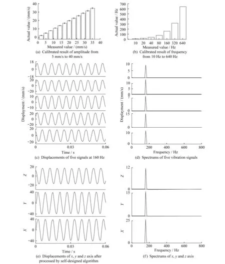
Firstly,we would like to test the frequency measurement ability of the system.The shaker system was placed in front of the laser system as vibration source,which was calibrated by a single-point LDV,and the distance from the system is 500mm.There are eight amplitude values selected from 5 mm/s to 40 mm/s and seven frequencies from 10 Hz to 640 Hz chosen for calibrating.The measurement results of amplitude and frequency are shown in Fig.3(a) and (b) respectively,which are excellent agreement with the values supplied by shaker system.So we can believe that the shaker system can supply precise frequency and amplitude signals for following experiments.
Then the vibration frequency is set to 160 Hz for further frequency measurement.Fig.3(c) shows the displacements of the five laser beams and Fig.3(d) shows their spectrums respectively.The displacement of beam 2 is shown at the bottom of the figure,whose phase differs by 90 degree from the other beams.Then displacements of all the three directions inx,yandzaxis can be achieved respectively based on the five displacements,which are shown in Fig.3(d) and their spectrums are shown in Fig.3 (e).All the frequency peaks are found at 160 Hz,the same as that from shaker system and single-point LDV.The results demonstrate that the system can supply precision measurement of frequency.

Fig.3 The experimental results of frequency measurement
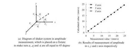
Then we would like to demonstrate the results of amplitude measurement of the system.The shaker system is placed on a fixture to measure the amplitude in three dimensions at the same time.Both the angle of elevation and inclination are about 54.7 degree.Fig.4(a) shows the diagram of vibration,whereVis the real vibration direction,andVx,VyandVzare components ofx,yandzaxis respectively.θx,θyandθzare all equal to about 54.7 degree.Fig.4(b) shows the results of amplitude measurement ofx,yandzaxis respectively with different frequency,and the numerical are in good agreement with those obtained from experiments.So we can believe that the system may have the potential to supply high-precision 3-D amplitude measurement in real time.

Fig.4 The experimental results of vibration measurement in 3-D direction
4 Conclusion
It is worth noting that the angle of beams (θin Fig.1(a)) will affect the measurement results seriously,especially amplitude measurement.In the system setup,both the angle inxandyaxis are 30 degree,and the value calculated by measurement result is about 30.52 degree.We can improve the precision apparently through signal processing in time domain.However,too complicated filtering algorithm may reduce real-time performance of the system.In the following work,we will try to introduce high-performance filtering algorithm like wavelet filter to enhance the measurement precision[9-10]. As we mentioned above,the system has potential to supply 3-D full-field measurement by scanning targets,andθcan be calculated precisely is one of the conditions.
In summary,we presented and tested a 3-D laser Doppler vibrometer using five laser beams.According to self-designed algorithm,the system can collect 3-D vibration information of targets based on five reflected scattering laser beams,simultaneously,without irradiating targets in all three directions.The experimental results show that both frequency and amplitude can be achieved inx,yandzaxis precisely.This study shows that the system has potential for measuring 3-D vibration information of targets.
Reference:
在这一课堂教学过程中,我以小组合作教学的方式展开课堂知识教学活动,为学生们营造了一个宽松、和谐的知识探究氛围,促进了学生课堂积极性的充分调动,进而促进了学生之间的交流与合作,推动了数学课堂的整体性建设,完成了生态化小学数学课堂构建任务。
[1]STANBRIDGE A B, MARTARELLI M,EWINS D J.Measuring area vibration mode shapes with a continuous-scan LDV[J].Measurement,2004,35(2):181-189.
[2]NISHIZAWA O, SATOH T,LEI X.Detection of shear wave in ultrasonic range by using a laser Doppler vibrometer[J].Review of Scientific Instruments,1998,69(6):2572-2573.
[3]LA J, CHOI J,WANG S,et al.Continuous scanning laser Doppler vibrometer for mode shape analysis[J].Optical Engineering,2003,42(3):730-737.
[4]FU Y, PEDRINI G,OSTEN W.Vibration measurement by temporal Fourier analyses of a digital hologram sequence[J].Applied Optics,2007,46(23):5719-5727.
[5]REMBE C, DRäBENSTEDT A.Laser-scanning confocal vibrometer microscope:theory and experiments[J].Review of Scientific Instruments,2006,77(8):083702.
[6]FU Y, GUO M,PHUA P B.Spatially encoded multibeam laser Doppler vibrometry using a single photodetector[J].Optics Letters,2010,35(9):1356-1358.
[7]FU Y, GUO M,PHUA P B.Multipoint laser Doppler vibrometry with single detector:principles,implementations,and signal analyses[J].Applied Optics,2011,50(10):1280-1288.
[8]REMBE C, KOWARSCH R,OCHS W,et al.Optical three-dimensional vibrometer microscope with picometer-resolution in x,y,and z[J].Optical Engineering,2014,53(3):034108.
[9]TAKEI M, OCHI M,SAITO Y.Image extraction of particle concentration at the plug front using 3D wavelets and comparison with LDV[J].Powder Technology,2004,142(1):70-78.
[10]TAKEI M, ZHAO T,YAMANE K.Measurement of particle concentration in powder coating process using capacitance computed tomography and wavelet analysis[J].Powder Technology,2009,193(1):93-100.
(编辑:张磊)
Three-dimensional laser Doppler vibrometry using five laser beams
GUO Hua,ZHANG Shenfeng,CHEN Kang,SONG Yunfeng,YE Gang
(Ningbo Sunny Advanced Instruments Co.,Ltd.,Yuyao 315400,China)
A 3-D laser Doppler vibrometer is presented for measuring the vibration of targets using five laser beams.All the five beams are focalized on a spot to illuminate a vibrating object which is covered by a piece of reflective strip,and the reflected scattering lights are processed by a high-precision signal processing system to get the vibration information.Then,the 3-D vibration information,including frequency and amplitude,inx,yandzaxis can be achieved respectively based on a self-designed algorithm in real time.The experimental results demonstrate that the system has the potential to be applied for high-precision 3-D vibration measurement.
laser Doppler vibrometry; 3-D vibration measurement; five laser beams
2015-08-06
国家重大仪器设备开发专项 (2013YQ470765)
郭华(1983—),男,工程师,主要从事激光测振仪方面的研究。E-mail:hguo@sunnyoptical.com
1005-5630( 2016) 03-0256-06
TH74
A
10.3969/j.issn.1005-5630.2016.03.013
