ALTERING CONNECTIVITY WITH LARGE DEFORMATION MESH FOR LAGRANGIAN METHOD AND ITS APPLICATION IN MULTIPLE MATERIAL SIMULATION∗†
2016-10-14RuiliWangXiaoLiangZhongLin
Ruili Wang,Xiao Liang,Zhong Lin
(1.Institute of Applied Physics and Computational Math.,Beijing 100094,PR China;
2.College of Math.and Information Science,Shandong University of Science and Technology,Shandong 266590,PR China)
ALTERING CONNECTIVITY WITH LARGE DEFORMATION MESH FOR LAGRANGIAN METHOD AND ITS APPLICATION IN MULTIPLE MATERIAL SIMULATION∗†
Ruili Wang1‡,Xiao Liang1,2,Zhong Lin1
(1.Institute of Applied Physics and Computational Math.,Beijing 100094,PR China;
2.College of Math.and Information Science,Shandong University of Science and Technology,Shandong 266590,PR China)
Abstract
A new approach for treating the mesh with Lagrangian scheme of finite volume method is presented.It has been proved that classical Lagrangian method is difficult to cope with large deformation in tracking material particles due to severe distortion of cells,and the changing connectivity of the mesh seems especially attractive for solving such issues.The mesh with large deformation based on computational geometry is optimized by using new method.This paper develops a processing system for arbitrary polygonal unstructured grid,the intelligent variable grid neighborhood technologies is utilized to improve the quality of mesh in calculation process,and arbitrary polygonal mesh is used in the Lagrangian finite volume scheme.The performance of the new method is demonstrated through series of numerical examples,and the simulation capability is efficiently presented in coping with the systems with large deformations.
Lagrangian scheme;large deformations;altering connectivity of mesh;finite volume method
2000 Mathematics Subject Classification 74S10
1 Introduction
The relationship between the distortion of the computational cells and the motion of the fluid plays an important role in numerical simulation of multidimensional compressible flow.Lagrangian or Eulerian coordinate is utilized to resolve this problem.However,there is a great difference between these two methods.For instance,the computational grid moves with the local fluid velocity in the Lagrangian description,while the grid is fixed in the Eulerian framework.The Lagrangian methods are prevalent in compressible multi-material fluid dynamics with high temperature and pressure,since this approach has well-resolved material interfaces and does not have advective diffusion term.However a large shearing distortion may lead to severely distorted cells and,inevitably,to mesh tangling,which will reduce the accuracy of the discrete scheme based on the grid,and the computation will run termination.Therefore,to resolve the large deformation is one difficulty and the focus in Lagrangian methods,and also the front field in CFD at present.
The deformation of the Lagrangian methods originates from two sources:One is un-robustness of the numerical scheme,and the other is grid evolution following the fluid.Thus highly qualified grid and robust scheme must be explored in order to make the Lagrangian methods having strong adaptation.
In this paper we propose an automatically local remeshing method based on changing connectivity of the mesh,which can be used to handle geometric intersection.It consists of two parts.First an arbitrary unstructured polygonal mesh is constructed through a collection of control nodes that are topologically organized into cells.By the way,the mesh is unstructured in the sense that individual cells may be constructed from arbitrary,non-uniform number of nodes.Second,changing connectivity of the mesh(topology transformation)is allowed during numerical simulation.Topological operations such as splitting and elimination of cells and edges,merging of cells is allowed in this process.This approach has successfully been implemented in a number of 2D codes of numerical analysis.
2 Governing Equations
Consider a two-dimensional multi-material compressible fluid system with elastic and plastic terms written in Lagrangian formalism given by:
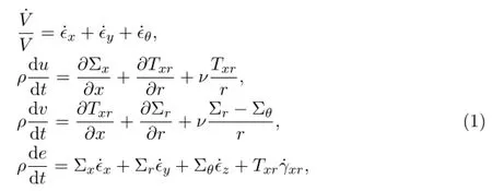
where x and r denote axes.In 2D planar problem,x is the level direction,r is the perpendicular direction.In cylindrical symmetry model,x is the axial symmetry direction,r is the perpendicular direction.u,v,ρ,e and p are x-velocity component,r-velocity component,density,internal energy and pressure respectively.The upper mark“·”denotes the derivative respect to time t,is the capacity ratio, ˙ϵx,˙ϵy,˙ϵzare positive strain ratios,˙γxris the shear strain ratio.ν is the geometry coefficient,ν=0 represents two dimensional planar problem,ν=1 is for two dimensional cylindrical symmetry model.
The artificial viscosity is imported in order to track the discontinuity near the shock,and it will be turned on only when the strain ratio is negative.We regard it to be the linear combination of Landshoff viscosity and Von Neumann-Richtmyer viscosity.
The Von Neumann-Richtmyer viscosity is in the following form:

where lNRhas length dimension,withA and aNRbeing N-R viscosity coefficient,A is the area of the grid cell.
The Landshoff viscosity is given by
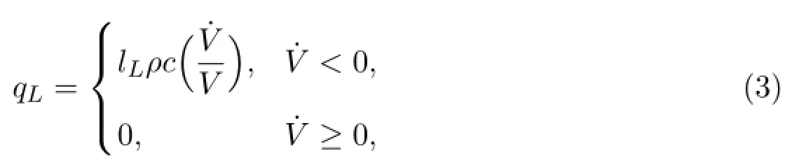
where lLis length,withand aLbeing the Landshoff viscosity coefficient.
3 Lagrangian Finite Volume on Arbitrary Polygonal Grid
In Lagrangian description,we suppose that edge is the external boundary(natural interface)and the interface of different fluids.Edges,cell and nodes compose the element unit.In this paper,the velocity and coordinates are defined on the nodes,while the other variables(such as density,pressure,stress and strain)are defined on the center of the cell,and they are assumed to be constants over a cell.
The discretion of momentum equation is given in the following:
For each node,e.g.α in Figure 1,we define the control volume to be connected by the center of neighboring cells and the center of edges surrounding the node α,where α1,α2,···,αmαare nodes around α,i1,i2,···,imαare the cell centers of the surrounding cells,β1,β2,···,βmαare the corresponding centers of the edges.
The discretisation formulations of velocities in α are given through discretion of the momentum equations in the following:
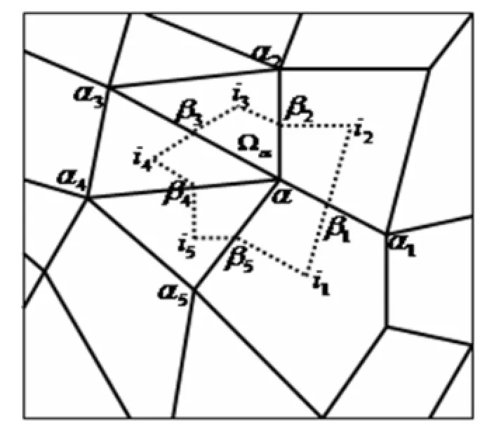
Figure 1:Control volume Ωαof momentum equation
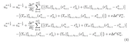
with

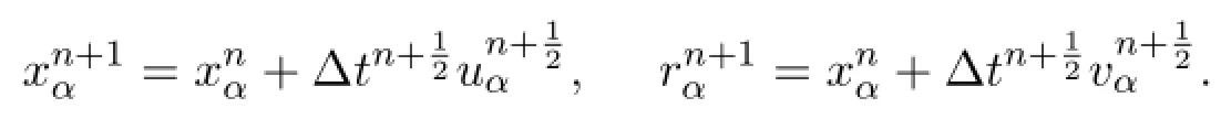
Using the new velocity in node α,we get the new position of node α for the next time step:
The discretization of the other equations are given in the following section. For example,the internal energy equation has the following form

We can discrete(6)on cell i,and use the following sequence to compute step by step
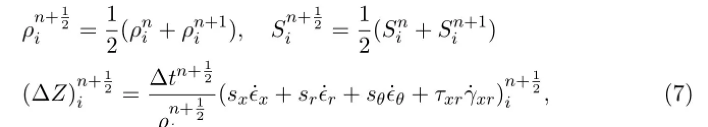
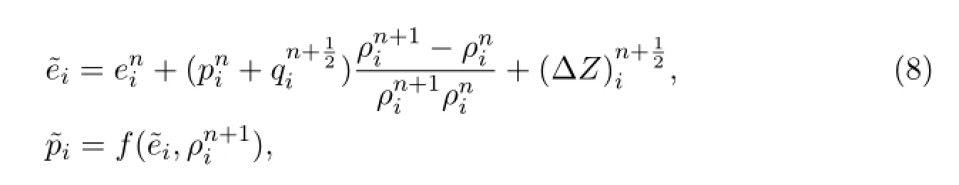
finally we get
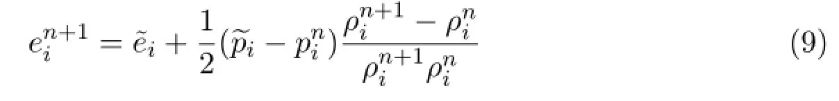
with

4 Polygonal Meshes and Motivation
Consider a 2D domain Ω,which is assumed to be a general polygon.We assume that the cells of the mesh,{c},cover the domain Ω without gaps or overlaps.Each cell may be a general polygon,and is assigned a unique index.For simplicity,it is also written by c.The set of vertices(nodes)of the polygons is denoted by{n},where each node has a unique index n.Then each cell can be defined by an ordered set of vertices.We denote the set of vertices of a particular cell c by N(c).Further,we denote the set of cells that share a particular vertex n by C(n).Note that each vertex may be shared by an arbitrary number of cells,and we denote connectivities of the cell and node by CNL(n)and NCL(c)respectively.The connectivity of the cell(CNL(n))is defined as an ordered set of nodes of around the cell,the connectivity of the node(NCL(c))is defined as an ordered set of cells of sharing the node(see Figure 2).
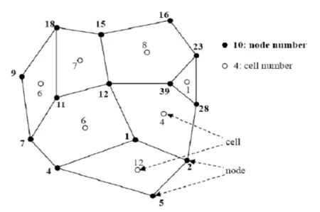
Figure 2:Polygonal mesh and notations
Set of nodes for cell c=12 is CNL(c=12)={5,2,1,4},and the set of cells sharing node n=39 is NCL(n=39)={1,8,4}.
To motivate our research,considering a situation with large deformations,quality of cells degrades and may become unacceptable for further calculation.For instance,the boundaries of Ω significantly changes as time progresses in numerical simulation of multidimensional fluid flow,such that the boundaries may become topologically disconnect in some of its region or singularities may be removed on the boundary. Here“singularities”means thin,wedge-shaped boundary cells,or intersection of cells and edges.If connectivity of the mesh can be changed in unacceptable position,then the general polygonal mesh may be generated in this case.A quadrilateral cell can be remeshed by using topological operations such as elimination of cells and edges to triangles.This stage will be described in Section 5.
5 Topology Transformations
These transformations include rearrangement of the local topological structure in order to arrive at a condition that will better admit a topology to form good elements.Some of these transformations have been described in other literatures,and they will be used here to handle geometric intersection algorithm.Each of the following transformations implements this research,and the basic transformations considered here are as follows.
5.1Distinguishing intersection
If we implement topological operations for poor quality and unacceptable element,two notions will be given in advance.Firstly,the concave-point in cell will be distinguished by using vector product

where k denotes unit vector in θ-direction,in 3D space(x-r-θ),k=(0,0,1)T.ϕ is the angle between the vectors(Rαj-Rαj-1)and(Rαj+1-Rαj).
If(Rαj-Rαj-1)×(Rαj+1-Rαj)·k<0,then the node αjis a concave-point in mesh-i.In Figure 3(a)the node αjis a concave-point in mesh-i;In Figure 3(b)the node αjis not a concave-point in mesh-i,which is a convex-point in mesh-i.
Then intersection of two lines will be distinguished.In Figure 4,if formulas

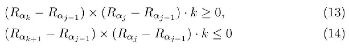
are all satisfied,then αj-1→αjand αk→αk+1intersect.
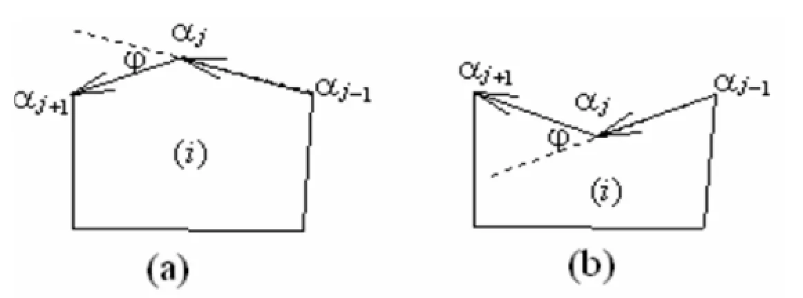
Figure 3:Concave-point and convex-point
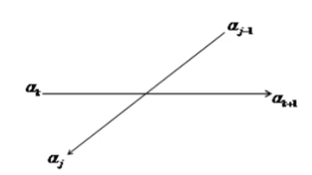
Figure 4:Intersection of two lines
It is easy to distinguish intersection for fragment of the mesh in computing procedure.In Figure 5,the concave-point αjat tn+1cuts across the edge αk→αk+1in mesh-i,then the mesh-i yields intersection.From this figure,it can be seen that logically mesh-i presents intersection,which cannot be handled during numerical simulation leading to reduce the accuracy of the discrete scheme or the computation will run termination.
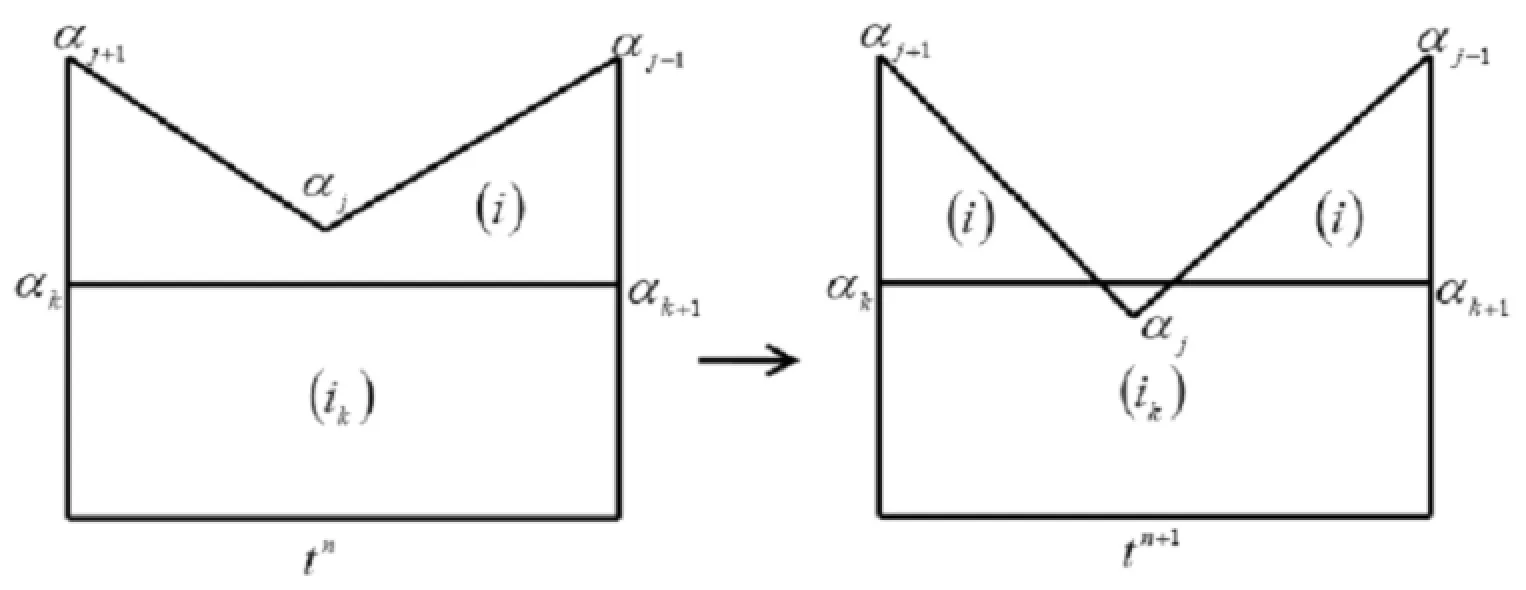
Figure 5:Intersection of two meshes
5.2Changing connectivity of the mesh techniques
There is a very simple algorithm to handle intersection for fragment of the mesh. This problem can be resolved by using local changing connectivity of the mesh techniques(“topological”remeshing).“Topological”remeshing may be based on topological operations such as splitting and elimination of cells and edges,merging of cells,optimization of poor topological quality mesh and further transformation of unacceptable cells into good cells.Based on unstructured arbitrary polygonal meshes,connectivity of the mesh changed in numerical simulation are defined as lots of topological operations in our LAD2D code[2],such as cutting down edge to the mesh-i on the left or on the right,big cutting down edge to the mesh-i on the left or on the right,merging or refining to the mesh-i,fracture on the node,normal fracture on the common edge of two cells,and so on.
In Figure 6,when the node αkis equal to the node αj+1(αk=αj+1)of the mesh-i at tn+1,the concave-point αjcuts across the edge αk→ αk+1in mesh-i(only neighbor edge αk→αk+1with αk),the connectivity of the mesh-i is changed,and eliminates the edge αj+1→αjof the mesh-i,which is defined as cutting down edge to the mesh-i on the left.From Figure 6,it is clear that topological operations with logically quadrilateral element are changed to those with triangles element.
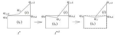
Figure 6:Cutting down edge to the mesh-i on the left
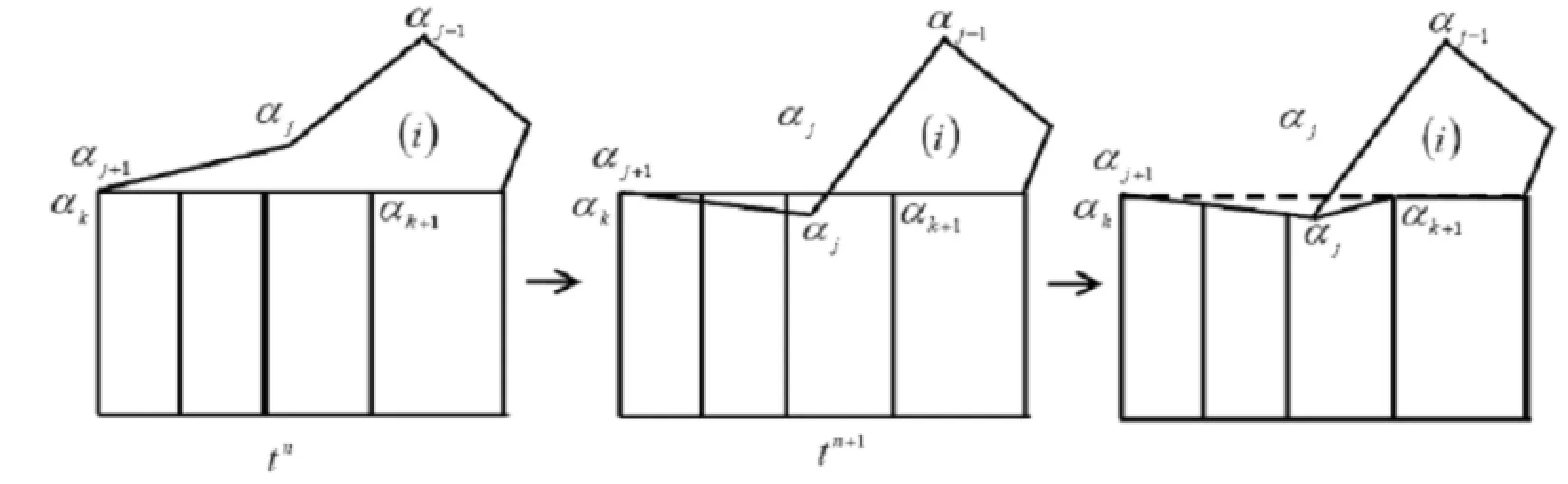
Figure 7:Big cutting down edge to the mesh-i on the left
In Figure 7,when the node αkis equal to the node αj+1(αk=αj+1)of the mesh-iat tn+1,the concave-point αjcuts across the edge αk→ αk+1in the mesh-i(the other neighbor edge αk→αk+1with αk),the connectivity of the mesh-i is changed,and eliminates the edge αj+1→αjof the mesh-i,which is defined as big cutting down edge to the mesh-i on the left.
In Figure 8,when the node αk+1is equal to the node αj-1(αk+1=αj-1)of the mesh-i at tn+1,the concave-point αjcuts across the edge αk→αk+1in the mesh-i(only neighbor edge αk→αk+1with αk),the connectivity of the mesh-i is changed,and eliminates the edge αj-1→αjof the mesh-i,which is defined as cutting down edge to the mesh-i on the right.
In Figure 9,when the concave-point αjat tn+1cuts across the edge αk→αk+1in the mesh-i,the connectivity of the mesh-i is changed,and eliminates the edge αk+1→ αkof the mesh-i,which is defined as merging to the mesh-i,and when refining the edge αk+1→αkto the mesh-i,is defined as refining to the mesh-i.
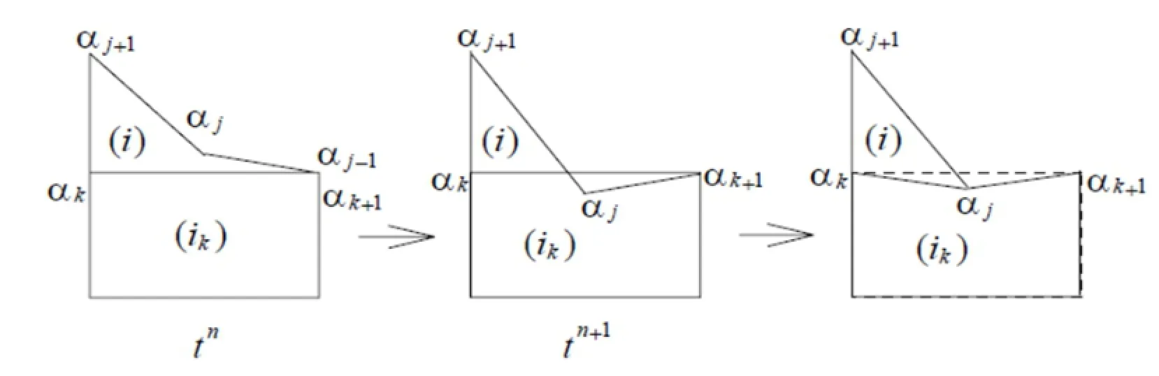
Figure 8:Cutting down edge to the mesh-i on the right
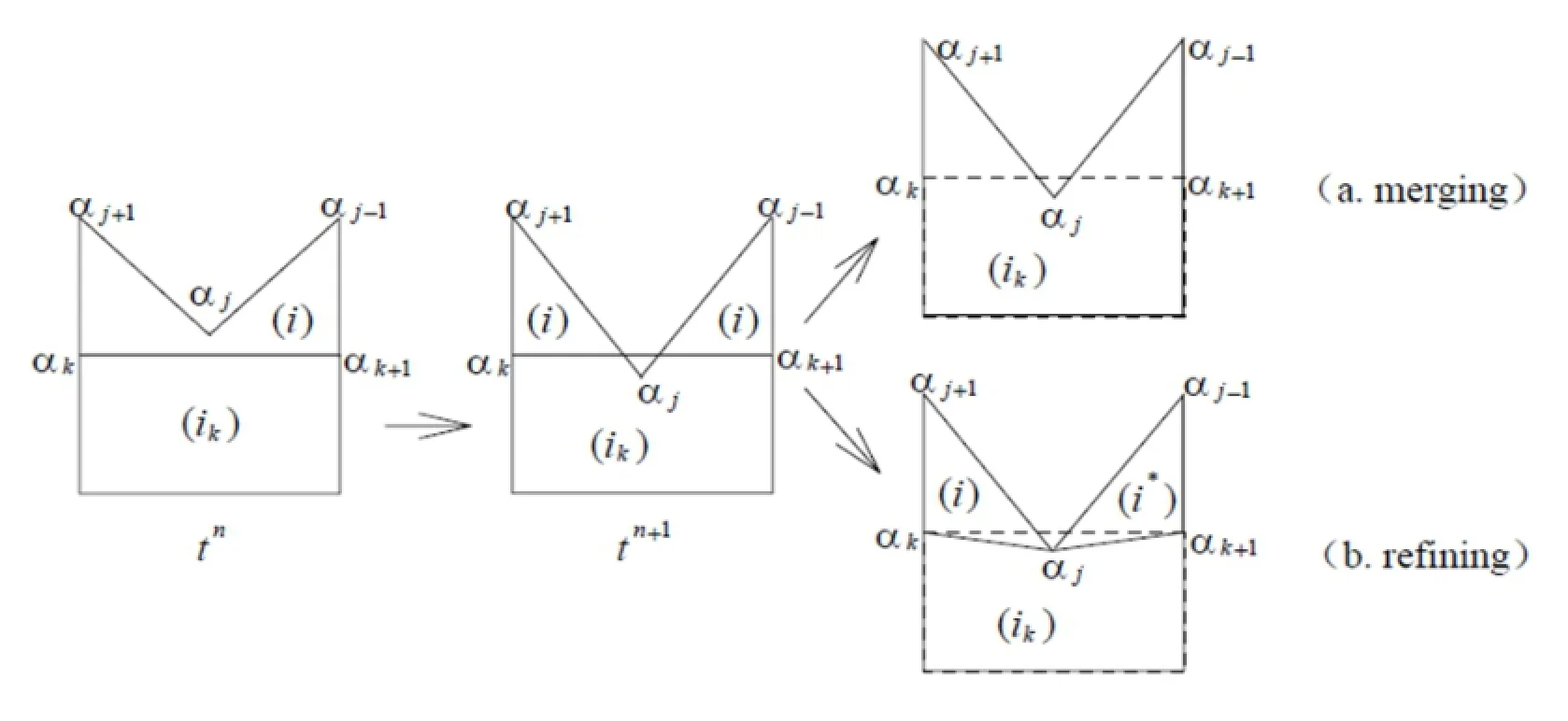
Figure 9:Merging or refining to the mesh-i
The proposed method of automatic local remeshing is implemented as a dynamic link library.In case of remeshing,the calling program receives information on all new removed and changed nodes and cells,and also on intersections of new and old cells which are needed to be rezoned.
After topological operations,Lagrangian solution is transferred(conservatively interpolated)from some polygonal meshes to another.
6 Numerical Tests
In this section,we present the numerical results obtained by the Lagrangian adaptive hydrodynamics code in 2-D space(LAD2D)code[2].LAD2D is a software project aiming at large scale scientific computing,which is developed and supported by IAPCM.This program is implemented at Yinhe-6 by IAPCM.
The first test is a simple test in planar geometry.It is designed by ourselves and involves break of the air-region with computing procedure.Most of the previous methods are suited for simulating this problem.The second test is“Diffraction of a detonation wave behind a backward-facing step”in r-z-ax symmetric geometry.Numerical simulation is used to validate the predictive capabilities of the new method by comparing with experimental data.
6.1The simple test case
Consider a simple problem with breaking of region in planar geometry.It is a two layers material problem.The computational domain is Ω=[0,1.0]×[0,0.12] as described in Figure 10.The lower layer is ideal gas.The gas-region is[0,1.0]×[0,0.10].The upper layer is an iron-metal(Fe),the region is[0.10,0.12],the initial densities are ρ1=0.0129,ρ2=7.85,the initial pressures are p1=0.1,p2=1.0,the initial velocity is zero in gas-region,the initial velocity is a distribution in the Fe-region as described by formula:
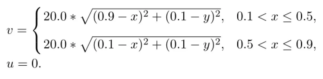
The ideal gas EOS p=(γ-1)ρe is used in this example with γ=1.4.The EOS for iron-metal(Fe)is p=(γ-1)ρe+c20(ρ-ρ0),with γ=4.075,ρ0=7.85g/cm3,c0=4.2km/s.
Figure 11 shows the process of automatic separating in gas layer.At the beginning,the iron-metal falls until it meets the boundary of gas,then the gas region is separated into two parts by using automatic local remeshing techniques.From the figure,it is clear that the connectivity of the mesh is changed.
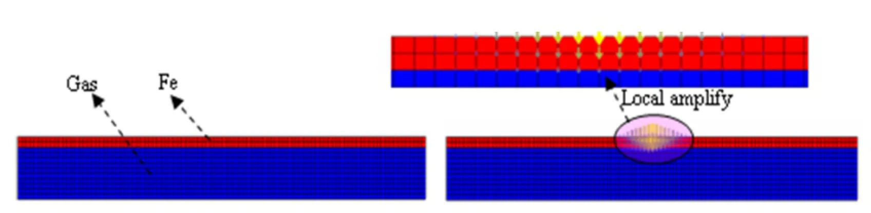
Figure 10:Schematics and meshes of model with initial condition

Figure 11:The process of automatic separating in gas layer
6.2 Diffraction of a detonation wave behind a backward-facing step
Diffraction of a detonation wave behind a backward-facing step is one of the fundamental topics in shock wave dynamics and is studied extensively by many researchers.The experiment is used in order to validate the predictive capabilities of the new automatic local remeshing method,based on Lagrangian methods,for problems with large deformations.
This model characterizes the detonation wave propagating through the channels with suddenly expending section.The left is a little section channel,and the right region is a large section channel.Initially,the region between the inlet and the end of the reaction zone is taken at the CJ state.The walls of the channel holds rigidly,and a no-reflection boundary condition is applied at the outlet.The computational domain Ω is described in Figure 12.From this picture,we can see that Ω is split into two regions filled with the explosive PBX9404 with parameters K=2.996,ρ0=1.84g/cm3,DJ=8.88km/s.The left region is Ω1=[0,3.0]×[0,0.5].The right region is Ω2=[3.0,6.0]×[0,3.0].Ω1is the driver section,where the top boundary condition satisfies a rigid wall condition and the bottom boundary condition is an axially symmetric.
6.2.1Reaction rate law
In the numerical simulation of detonation,combustion function F means the extent of explosive reaction.Three zones are distinctly distinguished(see Figure 13).
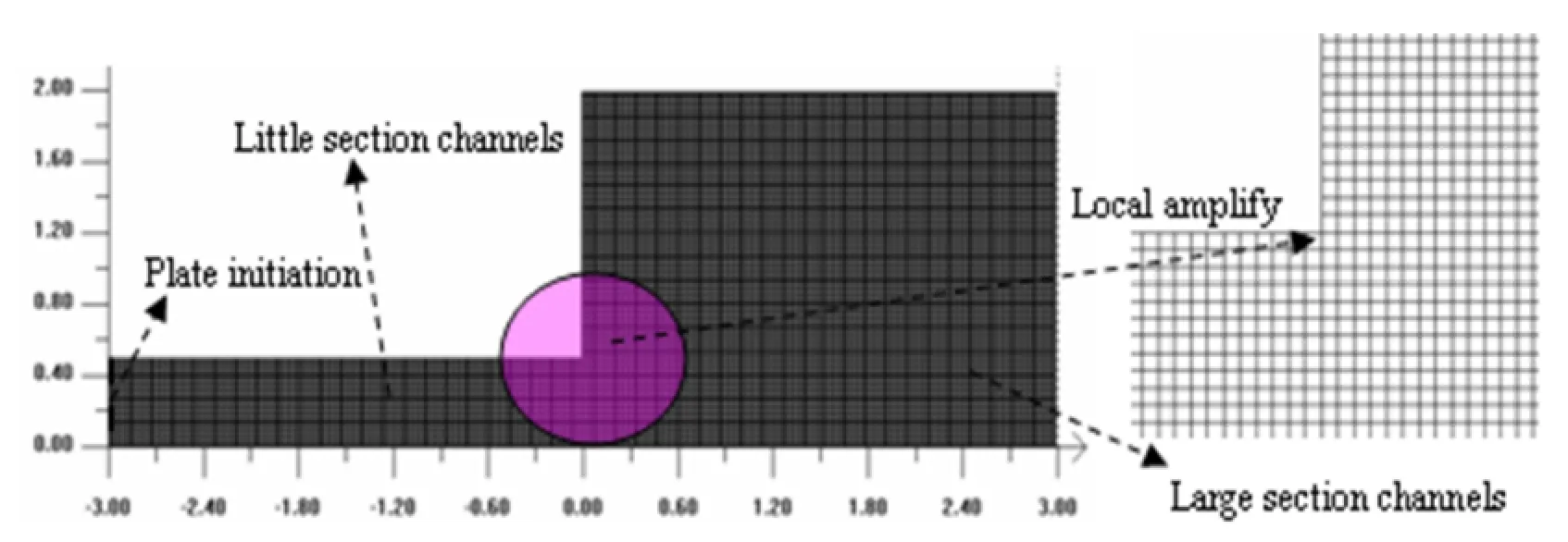
Figure 12:The computational model with initial meshes
The combustion function F is defined as

where nbis the constant to be defined,the Wilkins function F1is
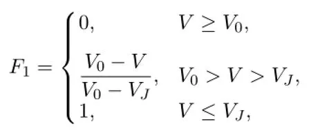
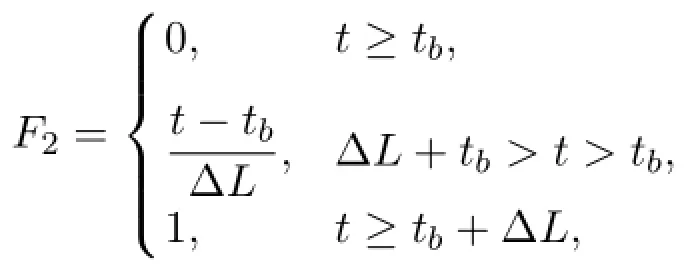
and C-J burning function F2is defined as
6.2.2Equation of state
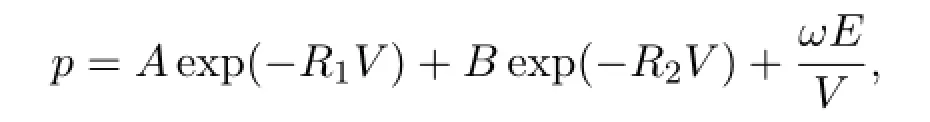
The Jones-Wilkins-Lee(JWL)EOS is used to describe the detonation products of the explosive,which has the following form:
6.2.3Results and discussion
Firstly,a steady CJ detonation wave propagates through the narrow segment unit diffraction around a 900corner,and then begins its travel through the narrow channel as a steady,undisturbed wave.It first senses a change in geometry upon arriving at the corner.As the detonation wave rounds the corner,the diffraction and re-initiation of detonations behind a backward-facing step generate spherical detonation wave.The detonation wave is weakened to deflagration partly in initial the large section channels according to detonation wave diffraction.The slip line could be formed,and the Mach reflection of detonation wave occurs when the detonation wave interacts with the wall.As time elapses,near the line of symmetry(bottom boundary of the computational domain),the wave interacts with the back-face of the step where a vortex exists,the wave becomes planar,the reflection on the wall transits to a Mach reflection and the reflected wave reflects off the upper wall again. Figure 14 shows the mesh in the 90ocorner.From this figure it is clear that topolo-gical operation with logically quadrilateral element is changed to that with triangles element.The mesh is so high deformation in near the corner that pure Lagrangian schemes eventually fail.
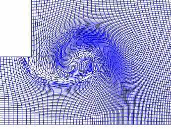
Figure 14:Meshes used in the numerical simulation
Figure 15 shows the computing mesh(upper)and density contours(lower)at three times.Diffraction through the 90ocorner also generates a stronger corner vortex.We compare numerical results with experimental data obtained from highspeed schlieren photography[6],which coincides with each other qualitatively.

Figure 15:Comparison between the numerical results and the experimental data at different times(Top:Grid used for solving the detonation diffraction;Center:Density contour from calculated result;Bottom:Data from the schlieren photography)
7 Conclusion
In this paper,we present a new approach for treating the mesh in Lagrangian framework based on finite volume method.An unstructured arbitrary polygonal mesh system is defined,and a Lagrangian phase with finite volume methods is obtained by which the solution on polygonal mesh is updated.The automatic local remeshing method is defined using topology transformations techniques.It allows the change of mesh connectivity,and Lagrangian solution is transferred(conserva-tively interpolated)from some polygonal meshes to another.On our numerical examples,the method is more robust in problems with large deformations,the predictive capabilities of the new automatic local remeshing method is showed.We will focus on the test of this method in the future.
References
[1]D.Benson,Computational methods in Lagrangian and Eulerian hydrocodes,Comput. Methods Appl.Mech.Eng.,99(1992),235.
[2]Ruili Wang,Zhong Lin,Wanzhi Wen,et al,Development and application of adaptive multi-media Lagrangian fluid dynamics software LAD2D,Computer Aided Engineering,23:2(2014),1-7.(in Chinese)
[3]J.C.Campbell,M.J.Shashkov,A compatible Lagrangian hydrodynamics algorithm for unstructured grids,Selcuk J.Appl.Math.,4:2(2003),53-70.
[4]P.Knupp,L.G.Margolin,and M.Shashkov,Reference Jacobin optimization-based rezoned strategies for arbitrary Lagrangian Eulerian methods,J.Comput.Phys.,176(2002),93-128.
[5]Alexander V.Skovpen,Modified algorithm for unstructured quadrilateral meshing,Snezhinsk,RFNC-VNIITF,September 2004,ISBN 5-902278-07-4,Revised on-line version,April 2005.
[6]S.Ohyagi,T.Obara,S.Hoshi,P.Cai,T.Yoshihashi,Diffraction and re-initiation of detonations behind a backward-facing step,Proceedings of the 18th Int.Colloquium on the Dynamics of explosions and reactive systems at Seattle,USA,2002.
[7]Yang Du,Wei Shen,Jian-zhong Zhou,Numerical simulation of detonation wave propagating through the channels with suddenly expending section,Explosion and Shock Waves,24:1(2004),75-79.(in Chinese)
[8]R.Wang,Q.Liu,W.Wen,Uncertainty quantification for JWL EOS parameters using non-intrusive polynomial chaos,Explosive and Shocks,35:1(2015),9-15.(in Chinese)
[9]R.Loubere,P.H.Maire,M.Shashkov,J.Breil,S.Galera,ReALE:A Reconnectionbased arbitrary-Lagrangian-Eulerian method,Journal of Computational Physics,229(2010),4724-4761.
[10]Lori A.Freitag,Carl Ollivier-Gooch,Tetrahedral mesh improvement using swapping and smoothing,International Journal for Numerical Methods in Engineering,40(1997),3979-4002.
(edited by Liangwei Huang)
∗The work was supported in part by the National Natural Science Foundation of China under Grant 11372051,Grant 11475029,in part by the Fund of the China Academy of Engineering Physics under Grant 20150202045.
†Manuscript received April 21,2016
‡Corresponding author.E-mail:Wang Ruili@iapcm.ac.cn
杂志排行

Annals of Applied Mathematics的其它文章
- SOLVABILITY FOR FRACTIONAL FUNCTIONAL DIFFERENTIAL EQUATION BOUNDARY VALUE PROBLEMS AT RESONANCE∗†
- THE SYMMETRIC POSITIVE SOLUTIONS OF 2n-ORDER BOUNDARY VALUE PROBLEMS ON TIME SCALES∗†
- BIFURCATIONS AND NEW EXACT TRAVELLING WAVE SOLUTIONS OF THE COUPLED NONLINEAR SCHR¨ODINGER-KdV EQUATIONS∗
- OPTIMAL DECAY RATE OF THE COMPRESSIBLE QUANTUM NAVIER-STOKES EQUATIONS∗†
- EFFECTS OF A TOXICANT ON A SINGLE-SPECIES POPULATION WITH PARTIAL POLLUTION TOLERANCE IN A POLLUTED ENVIRONMENT∗†
- L6BOUND FOR BOLTZMANN DIFFUSIVE LIMIT∗