钛合金电子束焊接表面残余应力的测试和有限元分析
2016-08-16刘晓佳雷永平吴中伟付鹏飞
刘晓佳, 林 健, 雷永平, 吴中伟, 刘 昕, 付鹏飞
(1.北京工业大学 材料科学与工程学院,北京 100124; 2.北京航空制造研究所 高能束流加工技术重点实验室,北京 100024)
钛合金电子束焊接表面残余应力的测试和有限元分析
刘晓佳1,林健1,雷永平1,吴中伟1,刘昕2,付鹏飞2
(1.北京工业大学 材料科学与工程学院,北京 100124; 2.北京航空制造研究所 高能束流加工技术重点实验室,北京 100024)
采用多束电子束流焊接Ti60钛合金,并利用小孔法和有限元分析方法分别测试和模拟焊后残余应力值。对焊前预热、焊后缓冷和焊前预热+焊后缓冷三种焊接工艺下的残余应力值进行比较,研究残余应力的分布规律。研究结果表明,在垂直焊缝截面上,纵向残余应力σx的模拟结果与测试结果在变化趋势上基本一致。在平行焊缝截面上,实测与模拟纵向残余应力σx的分布规律相似。证明了有限元模型的合理性和可靠性。采用预热+焊接的焊接工艺对残余应力影响不大,采用焊接+缓冷的焊接工艺可以改变残余应力的分布。
Ti60钛合金;电子束焊接;残余应力;有限元分析
随着航空发动机推重比的提高,压气机的工作条件更为复杂和苛刻。北京航空材料研究院研制的新型600 ℃高温钛合金Ti60,可以满足高性能航空发动机高压压气机的服役环境要求[1]。该合金在600 ℃下具有优异的蠕变抗力、疲劳强度和损伤容限性能,适用于先进航空发动机压气机600 ℃以下服役的高压段部件,如涡轮盘、叶片、整体叶盘等[2]。
Ti60钛合金整体叶盘间的焊接质量要求很高,真空电子束焊接(Electron Beam Welding, EBW)由于具有能量密度高、焊缝和热影响区窄、焊接变形小、工艺参数容易控制及真空焊接环境等优势,通常成为钛合金焊接方法的首选[3-6]。电子束焊接的加热方式为独特的高能流冲击方式,虽然构件变形范围小,但焊接残余应力由于温度梯度大而可能达到很大的数值[7-8],会降低焊接构件的刚性和尺寸稳定性,严重影响焊接接头的疲劳强度、抗脆断及抗应力腐蚀开裂的能力[9-10]。因此需要探究不同焊接工艺,研究电子束焊接接头残余应力的分布规律[11],分析获得降低焊接残余应力的焊接工艺。
小孔法是测量残余应力的一种较为成熟和可靠的方法,其测量精度高,对结构破坏性小,操作简单方便[12]。胡美娟等[13]进行了12 mm厚钛合金板电子束焊接温度场与应力场的有限元数值模拟,并将模拟得到的结果与小孔释放法实验检测的残余应力进行对比,结果表明计算结果与检测的残余应力分布规律基本一致。付鹏飞等[14]采用小孔法对电子束焊接GH536合金试板的残余应力分布趋势进行测试研究,表明焊缝区存在较低的应力峰值。Zhao等[15]研究了多光束同时以不同的热输入对材料不同的位置进行加工,研究结果证明利用多束电子束焊接技术能够减小接头的残余应力。Stone等[16]采用有限元分析方法对9 mm厚镍基高强合金平板电子束焊接过程进行了三维模拟计算,结果表明纵向残余应力的模拟结果同实验结果有良好的一致性,横向残余应力的差别较大。
上述研究只是进行了片面的实验测量或者有限元模拟,由于受实验工作量大的影响,没有把两者结果进行比较分析,进而指导其焊接工艺参数的优化。因此,本工作研究了Ti60钛合金电子束焊接残余应力的小孔法测试和ABAQUS模拟结果,比较和分析了采用三种焊接工艺焊后残余应力的分布规律,提出了比较合理的焊接工艺方案。
1 实验材料和方法
1.1实验材料
Ti60钛合金的化学成分见表1。

表1 Ti60钛合金化学成分(质量分数/%)
钛合金平板电子束焊接接头的外形尺寸及焊接参数如图1所示。平板的尺寸为200 mm×200 mm×12 mm,焊接速率为1.2 m/min,焊接方向如图1所示。

图1 Ti60钛合金平板电子束焊接接头外形尺寸示意图Fig.1 Shape size of the electron beam welding joint ofTi60 titanium alloy plate
1.2钛合金电子束焊的规范参数
钛合金平板电子束焊接分为以下三种工艺:(1)预热+焊接(A),即先对焊接的前方金属进行电子束辅助加热预热,然后进行电子束焊接;(2)焊接+缓冷(B),即先进行电子束焊接,然后在焊接电子束后方进行电子束辅助加热,以起到对焊缝金属缓冷的效果;(3)预热+焊接+缓冷(C),即先对焊接电子束的前方金属进行电子束辅助加热预热,然后进行电子束焊接,最后在焊接电子束后方进行电子束辅助加热。
经过工艺探究,电子束焊接Ti60钛合金的工艺参数如表2所示。
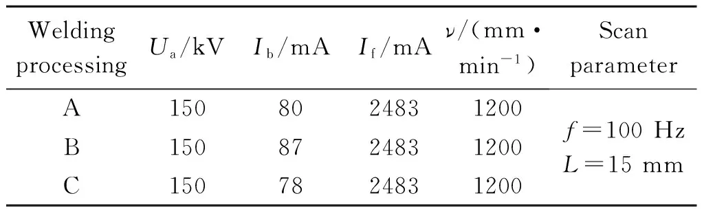
表2 Ti60钛合金电子束焊接的工艺参数
1.3小孔法残余应力测试和有限元分析
1.3.1小孔法残余应力测试方法
钛合金平板电子束焊接接头的表面残余应力测量方案如图2所示。在试板的焊接面上,沿着垂直焊缝中心线和平行焊缝中心线的两条测量线布置测量点。

图2 钛合金电子束焊接接头的表面残余应力测点布置方案Fig.2 Test point arrangement of the surface residual stress for the titanium alloy
采用小孔法测量试板上的焊接残余应力;采用型号为TJ120-1.5-φ1.5型三向应变花,应变片的分布角度为0°,90°和225°;采用XL2101C型程控静态电阻应变仪测量应变片上的应变变化值,其测量精度为1 μm。
在试板上钻取尺寸为φ1.5 mm×2 mm的小孔。假设表面残余应力处于平面应力状态,根据钻盲孔后三个方向上的应变释放量来推算试板上的残余应力数值,残余应力的推算公式如式(1)所示[17]:
(1)
式中:σ1为第一主应力;σ2为第二主应力;θ为第一主应力σ1与0°应变片的夹角;A,B为常数,与材料的弹性模量、泊松比和应变片的尺寸有关:
(2)
式中:d为应变片圆环直径;d0为钻孔直径;E为材料的弹性模量,对于钛合金,取值为121 GPa;ν为材料的泊松比,取值为0.29。
1.3.2钛合金电子束焊接接头的有限元分析
采用商用有限元软件ABAQUS进行钛合金电子束焊接过程的有限元分析(Finite Element Analysis,FEA)[18];采用顺序耦合的方法进行残余应力分析,即先采用传热模型分析钛合金电子束焊接过程的温度场分布,然后再将温度场分析结果作为初始条件加载在应力分析模型上,从而得到钛合金平板电子束焊接引起的残余应力场分布。
2 结果与分析
2.1三种焊接工艺残余应力测量结果
比较三种焊接工艺下的残余应力分布,其结果如
图3所示。由图3(a),(b)可见,在三种焊接工艺下,焊缝附近金属的残余应力值较高,纵向残余应力σx和横向残余应力σy均为残余拉应力,纵向残余应力σx的数值与材料的屈服极限相当,高达1000 MPa左右。而在距离焊缝中心线5 mm以上时,纵向残余应力σx值急剧下降,降至200 MPa以下。由图3(c),(d)可见,在三种焊接工艺下,距离焊缝中心线5 mm(y= 5 mm)处,纵向残余应力σx为数值较大的拉应力,其数值与材料的屈服极限相当,在焊缝的准稳态区域(即除去焊缝的起弧区和收弧区,焊缝的中点附近区域),数值较为稳定,符合焊接的准稳态区域分布特点。横向残余应力σy的数值略小于纵向残余应力σx。

图3 三种焊接工艺下焊接残余应力分布的比较 (a) 纵向残余应力σx在垂直焊缝测量线上的分布;(b)横向残余应力σy在垂直焊缝测量线上的分布;(c) 纵向残余应力σx在平行焊缝测量线上的分布;(d) 横向残余应力σy在平行焊缝测量线上的分布Fig.3 Distribution comparison of the welding residual stress under three kinds of welding processes (a) distribution of longitudinal residual stress σx in the vertical weld line;(b) distribution of transverse residual stress σy in the vertical weld line;(c) distribution of longitudinal residual stress σx in the parallel weld line;(d) distribution of transverse residual stress σy in the parallel weld line
2.2三种焊接工艺下的有限元分析结果
图4为三种焊接工艺下的残余应力数值模拟的结果比较图。由图4可见,三种焊接工艺条件下,在试板焊接面的残余应力分布结果差别不大,纵向残余应力的最大值均出现在距中心线约5 mm处。采用先焊接后缓冷的焊接工艺,纵向残余应力的数值较低。而预热+焊接和预热+焊接+缓冷焊接工艺引起的纵向残余应力数值差别较小,这个变化趋势与残余应力的测量结果相似。
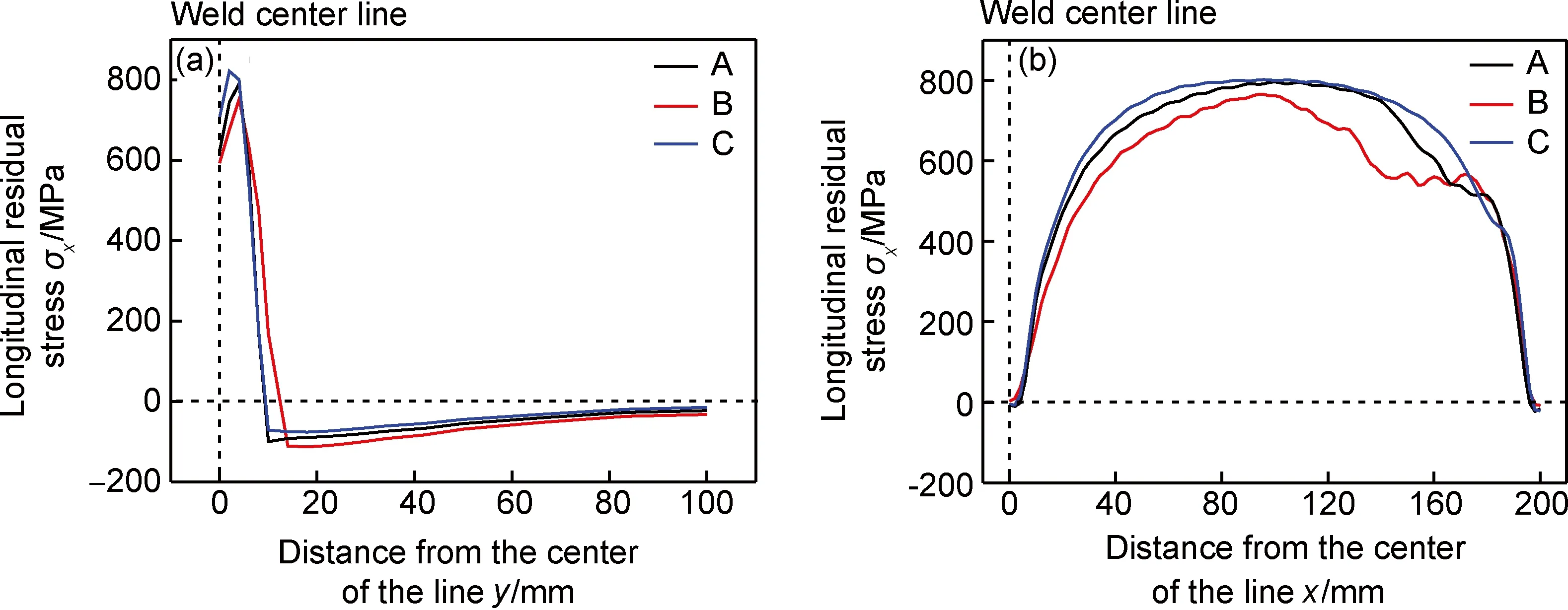
图4 三种焊接工艺下的残余应力数值模拟结果比较 (a) 垂直焊缝截面纵向残余应力σx; (b) 平行焊缝截面纵向残余应力σxFig.4 Comparison of numerical results under three kinds of welding processes (a) distribution of longitudinal residualstress σx in the vertical weld line;(b)distribution of longitudinal residual stress σxin the parallel weld line
2.3数值模拟结果与测试结果之间的比较
在垂直焊缝截面上,数值分析与测试结果的比
较如图5(a),(b)所示,在平行焊缝截面上的比较结果如图6所示。由图5(a)可见,在垂直焊缝截面上,纵向残余应力σx的数值模拟结果与实验测试结果在变化趋势上基本一致:均是在焊缝中心线附近,纵向残余应力σx数值较大,接近材料屈服极限的拉应力;数值较大的残余拉应力区域对于三种焊接工艺而言,存在一定的差异,这与接头的焊缝形状尺寸有关。

图5 三种焊接工艺下的数值分析与实验测试结果比较(垂直焊缝截面) (a)纵向残余应力σx;(b)横向残余应力σyFig.5 Comparison of numerical simulation and test results under three kinds of welding processes in the vertical weld line(a) distribution of longitudinal residual stress σx in the vertical weld line;(b) distribution of transverse residual stress σy in the vertical weld line

图6 三种焊接工艺下的数值分析与实验测试结果比较(平行焊缝截面)Fig.6 Comparison of numerical simulation and test results under three kinds of welding processes in the parallel weld line
图5(b)中横向残余应力σy的结果也存在同样问题,但是由于σy的测试结果相对于σx而言较小,因此差别更为明显。平行焊缝截面上,由图6的比较结果可知,平行焊缝截面的纵向残余应力σx的分布规律与图5(a)相似;但是具体数值上还存在一定差异,在预热+焊接工艺条件下,由于焊缝形状不均匀,实验测试的结果存在一定波动。
3 结论
(1)通过小孔法测试实验结果表明,在三种电子束焊接工艺下,残余应力分布规律相似:在垂直焊缝中心线上,纵向残余应力σx和横向残余应力σy均为残余拉应力,且在焊缝附近金属纵向残余应力σx的数值与材料的屈服极限相当;在平行焊缝中心线上,纵向残余应力σx为数值较大的拉应力,其数值与材料的屈服极限相当,而横向残余应力σy的数值略小于纵向残余应力σx。
(2)根据电子束焊接接头的形状和尺寸,考虑焊接过程中的温度场而建立的有限元数值模型分析和验证钛合金板面测试的残余应力分布规律。结果表明,数值模拟结果与实验测试结果在变化趋势上基本一致。
(3)采用预热+焊接的焊接工艺对残余应力影响不大,采用焊接+缓冷的焊接工艺可以改变焊接残余应力的分布。
[1] 黄旭,朱知寿,王红红.先进航空钛合金材料与应用[M]. 北京:国防工业出版社,2012.
[2] 赵永庆,葛鹏.我国自主研发钛合金现状与进展[J].航空材料学报,2014,34(4):51-61.
(ZHAO Y Q, GE P. Current situation and development of new titanium alloys invented in China[J]. Journal of Aeronautical Materials, 2014,34(4):51-61.)
[3] 郑志腾,有移亮,刘新灵,等.TC21钛合金电子束焊接件疲劳断口定量反推研究[J].材料工程,2013(11):50-56.
(ZHENG Z T, YOU Y L,LIU X L,etal. Quantitative reverse deduction from fatigue fracture of TC21 Ti alloy joint with electron beam welding[J]. Journal of Materials Engineering, 2013(11):50-56.)
[4] CAIAZZO F, CURCIO F, DAURELIO G,etal. Ti6Al4V sheets lap and butt joints carried out by CO2laser: mechanical and morphological characterization[J]. Journal of Materials Processing Technology, 2004, 149(1/2/3): 546-552.
[5] CAIAZZO F, CURCIO F, CAPECE M F M. Investigation on Ti6Al4V laser welding using statistical and Taguchi approaches[J]. Journal of Materials Processing Technology, 2005, 167(2/3): 422-428.
[6] FERRO P, ZAMBON A, BONOLLO F. Investigation of electron-beam welding in wrought Inconel 706-experimental and numerical analysis[J].Materials Science and Engineering A, 2005, 392(1/2): 94-105.
[7] 刘晓华,马英杰,李晋炜,等.TC4钛合金电子束焊接接头低周疲劳性能研究[J].航空材料学报,2013,33(3):53-57.
(LIU X H,MA Y J, LI J W,etal. Low cycle fatigue properties of electron beam welded TC4 titanium alloy[J]. Journal of Aeronautical Materials, 2013,33(3):53-57.)
[8] McDILL J M J, ODDY A S, REED R C. Predicting residual stresses and distortion when welding aero-engine alloys[J].Canadian Aeronautics and Space Journal,1998,44(2):68-72.
[9] 吴冰,张建勋,巩水利,等.厚板钛合金电子束焊接残余应力分布特征[J].焊接学报,2010(10):10-12.
(WU B, ZHANG J X, GONG S L,etal. Residual stress distribution of large thickness titanium alloy joints by electron beam welding[J]. Transactions of The China Welding Institution, 2010(10):10-12.)
[10]ABHAY K J. Metallographic analysis of embedded crack in electron beam welded austenitic stainless steel chemical storage tank[J].Engineering Failure Analysis,2001,8(2):157-166.
[11] 赵海燕,王鹏,巩水利,等.大厚度构件电子束焊接残余应力的测量及计算[J].清华大学学报(自然科学版),2013,53(10):1402-1406.
(ZHAO H Y, WANG P, GONG S L,etal. Measurements and computations of welding residual stresses in thick electron beam welded components[J]. Journal of Tsinghua University (Science and Technology Edition), 2013,53(10):1402-1406.)
[12]李未龙,余力,汪选国. 小孔法测试残余应力[J].武钢技术,2013,51(6):55-59.
(LI W L, YU L, WANG X G. Test of residual stress by hole drilling strain method[J].Wuhan Iron and Steel Corporation Technology, 2013,51(6):55-59.)
[13]胡美娟,刘金合.12mm厚钛合金平板电子束焊接的数值模拟[J].中国有色金属学报,2007(10):1622-1626.
(HU M J, LIU J H. Numerical simulation for electron beam welding of 12 mm-thickness titanium alloy plate[J].The Chinese Journal of Nonferrous Metals,2007(10):1622-1626.)
[14]付鹏飞,左从进,毛智勇,等.电子束焊接GH536合金残余应力分布小孔法测试[J].焊接学报,2005(11):21-23.
(FU P F, ZUO C J, MAO Z Y,etal. Weld residual stress distribution of GH536 superalloy with EBW measured by Mathar method[J]. Transactions of The China Welding Institution, 2005(11):21-23.)
[15]ZHAO H Y, WANG X, WANG X C,etal. Reduction of residual stress and deformation in electron beam welding by using multiple beam technique[J]. Frontiers of Materials Science, 2008(1): 66-71.
[16]STONE H J, ROBERTS S M, REED C. A process model for the distortion induced by the electron beam welding of a nickel-based superalloy[J]. Metallurgical and Materials Transactions A, 2000, 31(9): 2261-2273.
[17]宋天民. 焊接残余应力的产生与消除[M]. 北京:中国化学出版社,2004.
[18]黄丽婷,陈明和,谢兰生,等.超声冲击载荷对CP3钛合金焊接接头残余应力的影响[J].航空材料学报,2014,34(1):52-55.
(HUANG L T,CHEN M H, XIE L S,etal. Influence of ultrasonic impact load on residual stress distribution of welded joints for CP3 titanium alloy[J]. Journal of Aeronautical Materials, 2014,34(1):52-55.)
Residual Stress Test and Finite Element Analysis of Titanium Alloy Surface Obtained by Electron Beam Welding
LIU Xiaojia1,LIN Jian1,LEI Yongping1,WU Zhongwei1,LIU Xin2,FU Pengfei2
(1.College of Materials Science and Engineering, Beijing University of Technology, Beijing 100124, China; 2.Key Laboratory of High Energy Density Beam Processing Technology, Beijing Aeronautical Manufacturing Technology Research Institute, Beijing 100024, China)
Ti60 titanium alloy plates were welded by electron beam,and the welding residual stress was tested and simulated by the residual stress tester and finite element analysis. The comparison of the residual stress values caused in the three kinds of welding processes of pre-heating, slow cooling and both pre-heating and slow cooling was carried out. The residual stress distribution law was also studied. Results show that in the vertical welding section, the longitudinal welding residual stress tested is similar to that simulated as to the change trend; in the parallel welding section, the distributions of the tested and simulated longitudinal welding residual stress are similar. These prove that the finite element analysis is reasonable and reliable. The process of pre-heating has little influence on the welding residual stress, but the slow cooling process can change its distribution.
Ti60 titanium alloy;electron beam welding;residual stress;finite element analysis
(责任编辑:齐书涵)
2015-12-21;
2015-12-30
国家自然科学基金资助项目(51005004和51275006);北京市自然科学基金资助项目(3132006);北京市教委科研面上项目 (KM2012100050010)
林健(1979—),男,博士,副教授,主要从事汽车车身的轻量化方面的研究,(E-mail)linjian@bjut.edu.cn。
10.11868/j.issn.1005-5053.2016.4.005
TG404
A
1005-5053(2016)04-0035-06