Reactive dividing wall column for hydrolysis of methyl acetate:Design and control☆
2016-05-26LuminLiLanyiSunDelianYangWangZhongYiZhuYuanyuTian
Lumin Li,Lanyi Sun,*,Delian Yang,Wang Zhong,Yi Zhu,Yuanyu Tian
1State Key Laboratory of Heavy Oil Processing,China University of Petroleum,Qingdao 266580,China
2Synopsys,Inc.,690 East Middle field Road,Mountain View,CA 94043,USA
1.Introduction
Distillation is an important operation unit widely used in the chemical industry,and the development of distillation has attracted more and more attention in recent years[1,2].Process intensification,which focuses on reducing equipment size,improving process efficiency and decreasing energy requirements,is an attractive method to achieve the goal of lower cost and cleaner environment in the chemical process industry.Process intensification for distillation process mainly includes two aspects:(1)combining different columns together to improve the separation sequence,such as thermally coupled distillation column and dividing wall column(DWC);[3,4](2)integrating with other special processes,such as reactive distillation(RD),extractive distillation or distillation-membrane separation[5–7].
RD is a promising technology which can increase reaction conversion,reduce energy consumption,and improve selectivity and capital productivity[8].In recent years,RD has been extensively investigated due to the prominent advantages,and a great many achievements have been obtained in terms of process design and dynamic control[9–13].Gao et al.[13]proposed a new process based on RD for tert-amyl methyl ether synthesis,and the configuration was heat-integrated by dividing one RD column into the RD section and the stripping section.The simulation results demonstrated that this novel process is competitive on the operating costs and easy to control with only one tray temperature control loop,which proved the potentials of the heat-integrated RD approach.
DWC is made up of a single column with a dividing wall,through which it can separate ternary mixture and obtain pure products at one time.Since DWC can provide more than 30%savings on both the capital costs and energy costs,it has received increasing interests in chemical industry.In order to achieve further energy savings,researchers have concentrated on applying DWC to special distillation systems,such as reactive distillation,extractive distillation or azeotropic distillation[14–16].
Reactive dividing wall column(RDWC)has recently attracted great interests because it has the advantages of both RD and DWC.A method for conceptual design of the RDWC based on the minimum vapor flow method and the Vmindiagram was proposed by Sun and Bi[17].Mueller et al.[18]proposed the rate-based modeling method for RDWC taking the synthesis of diethyl carbonate as an example.Wang et al.[19]studied RD with thermal coupling columns for transesterification between methyl acetate(MeAc)and n-butanol,and the optimization and control were carried out.Although the steady-state design of RDWC has gained much attention,the controllability of RDWC is not extensively investigated for its complex thermal coupling configuration.Therefore it is necessary to study the dynamic performances for reaction systems with different characteristics.
Both methanol(MeOH)and acetic acid(HAc)are important raw materials in polyvinyl alcohol plants,and they could be produced from MeAc hydrolysis process.Some studies have investigated the hydrolysis process of MeAc.Lee et al.[20]studied two kinds of heat-integrated RD systems for MeAc hydrolysis,and the simulation results showed that the multi-effect distillation can achieve 38.26%energy savings compared with the base one.Gao et al.[21]employed a new process to hydrolyze MeAc,and a side withdrawal from RD column was separated only by one column.The simulation results showed that this novel process with high conversion of MeAc was more energy efficient.Sander et al.[22]conducted some experiments on the performance of RDWC for MeAc hydrolysis system,and the results indicated that using RDWC for MeAc hydrolysis was feasible.
The objective of this paper is to investigate the design and control of the RDWC for MeAc hydrolysis.First,the conventional reactive distillation process and RDWC process are presented considering a mixed feed with MeAc/MeOH(65 mol%/35 mol%).Then the two processes are simulated and optimized so as to obtain the minimum energy requirements.Next,the control performances of RDWC system are studied and an effective control structure is obtained.Some conclusions are presented in the last section.
2.Steady State Design
For the MeAc hydrolysis system,it is extremely important to forecast the non-ideal phase equilibrium data accurately among various components.Pöpken et al.[23]provided the UNIQUAC model parameters for this system,which is used to obtain the activity coefficients of components.Considering the dimerization of HAc in the vapor phase,Hayden–O'Conell second virial coefficient model is adopted for the vapor phase[24,25],and the model parameters applied here are from Aspen Plus®built-in database.The compositions and temperatures of azeotropes predicted by the model mentioned above at 101.325 kPa(1 atm)are shown in Table 1,which show good consistency to the experimental data provided by Horsley[26].
As shown in Table 1,there are two binary minimum boiling azeotropes in this system.Therefore,it is difficult to obtain high purity MeOH product due to the effect of MeAc azeotropes.It is favorable to remove the MeAc azeotropes as light components,and the residual mixture,without the effect of azeotropes,is easy to be separated into a high purity of MeOH product.Meanwhile,considering the extractive effect of water to MeOH on the MeAc/MeOH azeotrope,it is reasonable to set an extractive section in RD column,which can decrease the MeOH content and flow rate of the MeAc recycle stream.
The MeAc hydrolysis is a reversible reaction with the following expression:

The reaction kinetics for the hydrolysis of MeAc have been extensively investigated[20,21,24,25],which include two kinds of kinetic models,namely pseudohomogeneous and adsorption-based models[27].Gao et al.[21]reported that it was accurate to simulate MeAc hydrolysis reaction using pseudohomogeneous model.Zhai et al.[28]also used the pseudohomogeneous model in this hydrolysis reaction,which is adopted in this study shown as following:

In the above equations,R is the reaction rate with the unit of mol·L−1·h−1,xipresents the molarity of component i in the unit of mol·L−1,kfand krare the forward and reverse reaction kinetic constants,respectively,with the unit of L·mol−1·h−1.In addition,extremely low equilibrium constant,about 0.013 at 50°C,is another important characteristic of this hydrolysis system.Therefore,in order to increase the reaction conversion,the reactant water should be excessive,and the ratio of water to MeAc/MeOH feed is set as 5.0.In this study,the overall simulation works are carried out using the commercial software Aspen Plus®.The shortcut design is performed to obtain the initial values for rigorous simulation.Then the rigorous RadFrac module based on the equilibrium-stage type is chosen for the simulation of the distillation columns.The UNIQ-HOC physical property method is selected for this MeAc hydrolysis system.The specification for this hydrolysis system is assumed as follows:the catalyst possesses half of the holdup volume in each reactive tray;the tray holdup is calculated based on the weir height of 60 mm and column diameter.Moreover,MeOH product is specified at the purity of 99.9 mol%and the MeOH impurity in the bottom of MeOH column is specified with 0.1 mol%.
2.1.Design of conventional process for MeAc hydrolysis
There are several types of flow sheets for the hydrolysis process of MeAc.Sun et al.[29]analyzed the characteristics of different processes for MeAc hydrolysis,and according to the practical industrial applications,a reasonable flow sheet was proposed as shown in Fig.1A.It should be pointed out that the MeAc/MeOH feed and products in the conventional process are consistent with those in the RDWC process.The conventional process includes a RD column and a separation column(MeOH column).The catalyst is set in the middle of RD column,and the fresh water is fed into the column above the top of catalyst bed.The unreacted MeAc and some MeOH are withdrawn from the top of RD column due to the extractive effect of water,and the distillate is mixed with the MeAc/MeOH feed and fed to the bottom of catalyst bed.Meanwhile,the bottoms of RD column,including the mixture ofMeOH,water and HAc,are fed into another column to obtain MeOH product and water/HAc mixture.

Table 1 Predicted thermodynamic data of MeAc hydrolysis system

Fig.1.(A)Conventional process and(B)RDWC process for MeAc hydrolysis system.
2.2.Design of RDWC process for MeAc hydrolysis

Fig.2.Influence of vapor split ratio and reflux ratio of the main column on the reboiler duty.
The RDWC flow sheet for MeAc hydrolysis is shown in Fig.1B.In this RDWC flow sheet,a main column and a rectifier are integrated in one column,which includes two condensers and one reboiler.The water and MeAc/MeOH feeds are driven into the top and bottom reactive section of the main column respectively.The distillate of main column,which includes unreacted MeAc with some MeOH,is mixed with fresh MeAc/MeOH feed in order to avoid azeotrope in the following separation process.The mixture of MeOH,water and HAc will be separated in the rectifier and 99.9mol% MeOH product is obtained in the distillate.The bottoms of RDWC are the water/HAc mixture that can be separated in subsequent columns.
When the RDWC flow sheet is determined,the distillate flow rate,reflux ratio of the main column,withdrawal flow rate and vapor split ratio can be manipulated.Here the vapor split ratio is defined as the ratio of the vapor fed into the rectifier to the vapor fed into the main column.The distillate flow rate and withdrawal flow rate are varied to meet the two product purities,and the reflux ratio of the main column and the vapor split ratio are manipulated to minimize the reboiler duty.Fig.2 illustrates the influences of the vapor split ratio and the reflux ratio of main column on the reboiler duty with the specification of product purities.As shown in Fig.2,the optimal reboiler duty of this RDWC process is 12.51 MW with the vapor split ratio 0.6 and the reflux ratio 13.Note that the conventional process is optimized using the similar method,and the simulation results show that the total reboiler duties for conventional process are 15.65 MW.Hence the energy savings of RDWC can be achieved by 20.1%when compared with that of conventional process.Figs.3 and 4 present the simulation results of the conventional RD and RDWC processes,respectively.Table 2 shows the detailed comparison between the conventional RD process and RDWC process, and it can be concluded that the energy requirement of RDWC process can be greatly reduced when adopting the RDWC design for the methyl acetate hydrolysis. The composition and temperature profiles in RDWC are shown in Fig. 5.

Fig.3.Detailed simulation parameters of the conventional RD flow sheet for MeAc hydrolysis.

Fig.4.Detailed simulation parameters of the RDWC flow sheet for MeAc hydrolysis.

Table 2 Detailed comparison between the conventional RD process and RDWC process
3.Process Dynamics and Control of RDWC
For distillation process, the steady-state temperature or composition profile changes when the feed flow rate or composition varies.Through adjusting the temperature or composition of sensitive stages,the purity of MeOH product should be maintained at 99.9 mol%and the MeOH impurity at the bottoms should be less than 0.1 mol%.Therefore,the control objective of this RDWC system is to maintain the stoichiometric balance and keep product purities at their designed values after introducing disturbances in feed stream.
3.1.Degrees of freedom analysis and inventory control
The RDWC,which includes a main column and a rectifier,is equivalent to the thermal coupling columns in thermodynamics.In this system,there are 12 control degrees of freedom,including the MeAc/MeOH feed flow rate,the water feed flow rate,the condenser duty and reboiler duty of the main column,the distillate flow rate and bottom flow rate of the main column,the reflux flow rate of the main column,the two thermal coupling streams flow rate,and the condenser duty,distillate flow rate and reflux flow rate of the rectifier.Among these control degrees of freedom,six are used for inventory control of the system.MeAc/MeOH feed flow rate is used to control the throughput;the vapor flow rate withdrawn from the main column maintains the vapor split ratio at designed value.However,as it is difficult to measure the vapor flow rate of a specific tray in practical column,the definition of vapor split ratio is changed to the ratio of the side draw flow rate of the main column to the vapor flow rate from the reboiler in the control perspective.The remaining four degrees of freedom are used to control the product purities and maintain stoichiometric balance.Fig.6 gives the detailed control strategy of this RDWC process.As mentioned earlier,there are six inventory control loops in this RDWC system,including four liquid level control loops and two column pressure control loops.As shown in Fig.6,these inventory control loops are arranged as follows:the reflux drum levels of the two columns are controlled by manipulating their distillate flow rates;the column sump levels of the two columns are controlled by their bottom flow rates,and the column pressures are maintained by their condenser duties,respectively.Table 3 summarizes the proposed control loops of the RDWC process.

Fig.5.Pro files of composition and temperature of RDWC.
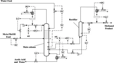
Fig.6.Process control configurations of RDWC.PC-pressure control;LC-level control;FC- flow control;TC-temperature control;X-ratio control.
3.2.Control of product qualities and stoichiometric balance
The analysis above shows that there are still four remaining control degrees of freedom(reflux flow rate of the main column,water feed flow rate,reboiler duty of the main column,reflux flow rate of rectifier),which are used to control the qualities of three products and the stoichiometric balance.The distillate composition of RDWC is determined by the thermodynamics property of the system.Hence the four remaining manipulating variables have little effect on the composition of this recycle stream.As a result,instead of controlling the purity of the recycle stream,the reflux ratio of the main column is fixed for the desired separation efficiency,and the other three control degrees of freedom are used to control the MeOH product purity,the bottom impurity of MeOH and the stoichiometric balance between the two feeds,which leads to a 3×3 multivariable control system.
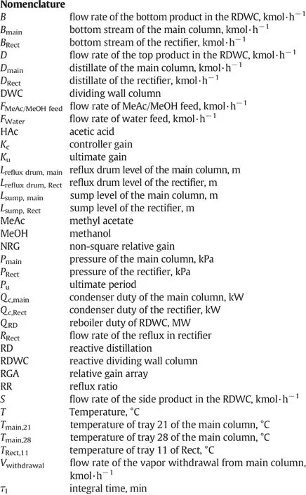
For this RDWC control issue,the stoichiometric balance between reactants must be kept constant.Feed ratio control is the simplestalternative for the equilibrium control,while Luyben[12]pointed out that this simple ratio control was not feasible in the practical application due to the measurement bias of feed flow rate.Then he suggested that the compositions at some column trays can be controlled by reactant feed flow rate[12].Considering the large measurement delays as well as high investment and maintenance cost of composition analysis,temperature control is usually used instead of composition control in practical industrial application.Therefore,in this control system,the temperature control loops of specific column trays are adjusted to control the product quality and stoichiometric balance,and the control design procedure is determined on the basis of non-square relative gain(NRG)method[30,31]and relative gain array(RGA).It is suggested that the control variable pairing is as follows:water feed flow rate controls the temperature of tray 28 of the main column,reboiler duty controls the temperature of tray 21 of the main column,and reflux flow rate of rectifier controls the temperature of tray 11 of the rectifier.More detailed information about the selection of temperature control trays can be found in the appendix section.In this work,liquid level is controlled by proportional-only controller,and proportional-integral controllers are used for flow rate,pressure and temperature controls.For the temperature control loops,the delay time of 1 min is assumed.The relay feedback test tuning is performed for every temperature control loop to obtain Kuand Pu,and the control loops are turned as the following order: first the Tmain,21-QRDloop,then the TRect,11-RRectloop,and last the Tmain,28-FWaterloop,and then again in this order[32].

Table 3 Details for the control loops of the RDWC process
3.3.Control performance
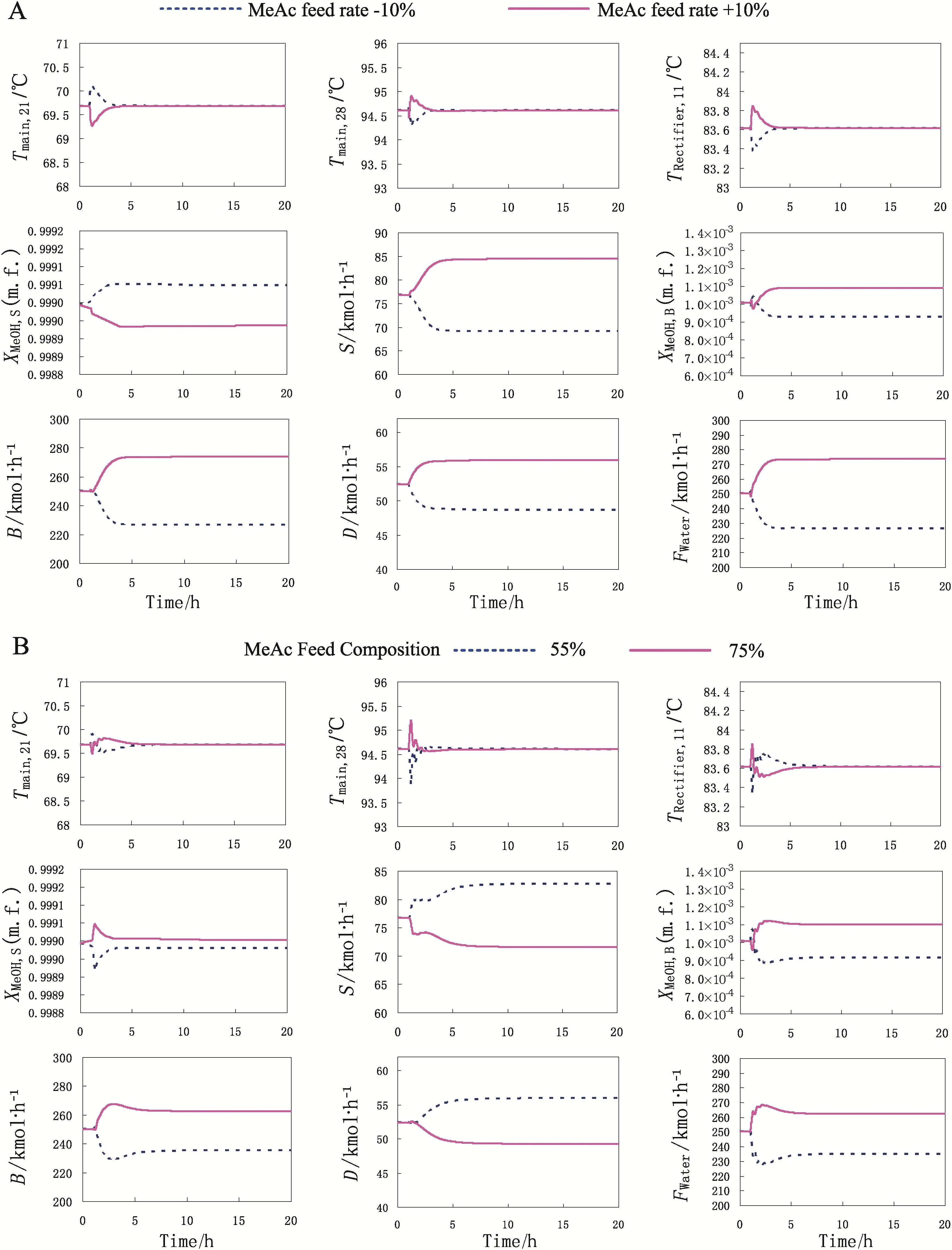
Fig.7.Temperature control responses for(A)±10%MeAc/MeOH feed mole flow rate changes and(B)±10%MeAc/MeOH feed mole composition changes.
The following is to test this control structure by performing dynamic simulation using Aspen Dynamics®.The flow rate and composition of MeAc/MeOH feed are disturbed respectively at 1 h to test the performance of the proposed control structure.Fig.7 presents the dynamic responses for±10%changes in MeAc/MeOH feed,in which the D,B and S represent the flow rate of the top,bottom and side products in RDWC,respectively.As shown in Fig.7,the temperature of each sensitive tray can be converged to the set point when different disturbances are introduced,thus the temperature for each stage is well controlled.The Tmain,28-FWaterloop calls for a larger recycle and water feed flow as the throughput increases,which indicates that this temperature control loop can successfully control stoichiometric balance between the two reactants,thus the hydrolysis conversion of MeAc can be maintained.The temperature of stage 11 in rectifier settles soon after the disturbances,hence the MeOH product can also achieve a steady state in a short time.It also can be seen that the flow rates can achieve stable values in less than 3 h after the system is disturbed.Although the compositions of MeOH product and bottom product of the main column cannot converge to their original values,the largest deviation is less than 0.01%for feed disturbances,which can satisfy the quality requirement of products. Fig. 7 also shows that the water feed flow rate increases with the rise of MeAc composition in MeAc/MeOH feed, thus the hydrolysis conversion of MeAc can be kept.Overall results of this control structure present that the MeOH product can be brought close to its set point as shown in Fig. 7. Therefore, this control structure is effective for the RDWC system.
4.Conclusions
In this paper,the design and control of the MeAc hydrolysis using RDWC are investigated.The RDWC sequence combines the RD column and the MeOH separation column,leading to a single column with a dividing wall.The optimal operation parameters are obtained through sensitivity analysis,and the results show that this novel RDWC process can save reboiler duty by 20.1%compared with the conventional process.
The control strategy for this attractive RDWC process is proposed.The non-square relative gain method and relative gain array method are used to determine the temperature control trays and pair the manipulated and controlled variables.The PI control parameters are obtained by relay-feedback method and Tyreus–Luyben setting.The results indicate that the temperature control loops can be used to control the products quality as well as the stoichiometric balance successfully.It is demonstrated that this control structure can overcome the feed disturbances effectively.
Appendix
The control design procedure on the basis of non-square relative gain(NRG)method and relative gain array(RGA)is as follows:
(1)Use NRG to select temperature control trays.The larger row sums of the NRG indicate possible temperature control trays;
(2)Use RGA for variable pairing;
(3)Use sequential relay feedback test to find the ultimate gain(Ku)and ultimate period(Pu);
(4)Use the simple version of Tyreus and Luyben tuning, controller gain(Kc)=Ku/3 and integral time(τ1)=2Puto set the tuning constants for PI controllers.
In order to calculate the steady-state temperature gain of each tray in the linear range,sensitivity analysis is performed by changing extremely small step(±0.01%)in the manipulated variables(water feed flow rate,reboiler duty and reflux flow rate of the main column).The steady-state sensitivity of the tray temperature in the two columns is shown in Fig.A1,and the results show that temperature responses are quite linear for the small disturbances.
The NRG is used to find the temperature control trays in the columns.Fig.A2 shows the row sums of the NRG for this system,and the trays with the largest row sum of the NRG in each column are selected as the temperature control trays,which are the trays 21 and 28 of the main column and tray 11 of the rectifier.Table A1 shows the results of steady-state gain matrices and RGA analysis between manipulated variables and controlled variables.Therefore,the control variable pairing is as follows:water feed flow rate controls the temperature of tray 28 of the main column,reboiler duty controls the temperature of tray 21 of the main column,and reflux flow rate of rectifier controls the temperature of tray 11 of the rectifier.

Fig.A1.Sensitivity of tray temperature for±0.01%manipulated variables changes.
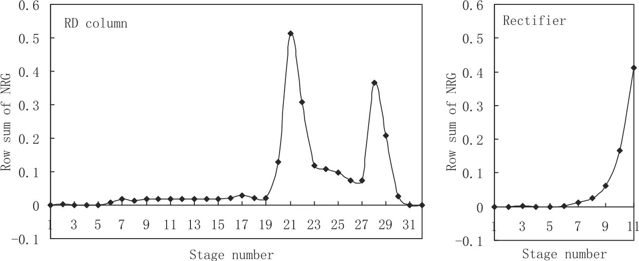
Fig.A2.Row sums of NRG for main column and rectifier of RDWC.

Table A1 Steady-state analysis of RDWC
[1]I.E.Grossmann,M.Martín,Energy and water optimization in biofuel plants,Chin.J.Chem.Eng.18(6)(2010)914–922.
[2]J.Fang,H.Zhao,J.Qi,C.Li,J.Qi,J.Guo,Energy conserving effects of dividing wall column,Chin.J.Chem.Eng.23(6)(2015)934–940.
[3]J.A.Caballero,I.E.Grossmann,Synthesis of complex thermally coupled distillation systems including divided wall columns,AIChE J.59(4)(2013)1139–1159.
[4]I.Dejanović,L.Matijašević,Ž.Olujić,Dividing wall column—A breakthrough towards sustainable distilling,Chem.Eng.Process.49(6)(2010)559–580.
[5]A.A.Kiss,A.C.Dimian,G.Rothenberg,Biodiesel by catalytic reactive distillation powered by metal oxides,Energy Fuel 22(1)(2007)598–604.
[6]W.L.Luyben,Comparison of extractive distillation and pressure-swing distillation for acetone/chloroform separation,Comput.Chem.Eng.50(2013)1–7.
[7]C.Zhao,J.Wang,Z.Luan,Preparation of high concentration polyaluminum chloride with high Alccontent by membrane distillation,Chin.J.Chem.Eng.19(1)(2011)173–176.
[8]B.Yang,J.Wu,G.Zhao,H.Wang,S.Lu,Multiplicity analysis in reactive distillation column using Aspen Plus,Chin.J.Chem.Eng.14(3)(2006)301–308.
[9]A.C.Dimian,C.S.Bildea,F.Omota,A.A.Kiss,Innovative process for fatty acid esters by dual reactive distillation,Comput.Chem.Eng.33(3)(2009)743–750.
[10]S.Li,D.Huang,Simulation and analysis on multiple steady states of an industrial acetic acid dehydration system,Chin.J.Chem.Eng.19(6)(2011)983–989.
[11]C.S.Bildea,R.Győrgy,E.Sánchez-Ramírez,J.J.Quiroz-Ramírez,J.G.Segovia-Hernandez,A.A.Kiss,Optimal design and plant wide control of novel processes for di-n-pentyl ether production,J.Chem.Technol.Biotechnol.90(6)(2015)992–1001.
[12]W.L.Luyben,Distillation design and control using Aspen simulation,John Wiley&Sons,Hoboken,New Jersey,2006.
[13]X.Gao,F.Wang,H.Li,X.Li,Heat-integrated reactive distillation process for TAME synthesis,Sep.Purif.Technol.132(2014)468–478.
[14]A.A.Kiss,J.Pragt,C.Van Strien,Reactive dividing-wall columns-how to get more with less resources?Chem.Eng.Commun.196(11)(2009)1366–1374.
[15]L.Sun,Q.Wang,L.Li,J.Zhai,Y.Liu,Design and control of extractive dividing wall column for separating benzene/cyclohexane mixtures,Ind.Eng.Chem.Res.53(19)(2014)8120–8131.
[16]A.A.Kiss,J.David,P.C.Suszwalak,Enhanced bioethanol dehydration by extractive and azeotropic distillation in dividing-wall columns,Sep.Purif.Technol.86(2012)70–78.
[17]L.Sun,X.Bi,Shortcut method for the design of reactive dividing wall column,Ind.Eng.Chem.Res.53(6)(2014)2340–2347.
[18]I.Mueller,E.Y.Kenig,Reactive distillation in a dividing wall column:Rate-based modeling and simulation,Ind.Eng.Chem.Res.46(11)(2007)3709–3719.
[19]S.J.Wang,D.S.Wong,S.W.Yu,Design and control of tr ansesterification reactive distillation with thermal coupling,Comput.Chem.Eng.32(12)(2008)3030–3037.
[20]H.Y.Lee,Y.C.Lee,I.L.Chien,H.P.Huang,Design and control of a heat-integrated reactive distillation system for the hydrolysis of methyl acetate,Ind.Eng.Chem.Res.49(16)(2010)7398–7411.
[21]X.Gao,X.Li,H.Li,Hydrolysis of methyl acetate via catalytic distillation:simulation and design of new technological process,Chem.Eng.Process.49(12)(2010)1267–1276.
[22]S.Sander,C.Flisch,E.Geissler,H.Schoenmakers,O.Ryll,H.Hasse,Methyl acetate hydrolysis in a reactive divided wall column,Chem.Eng.Res.Des.85(1)(2007)149–154.
[23]T.Pöpken,L.Götze,J.Gmehling,Reaction kinetics and chemical equilibrium of homogeneously and heterogeneously catalyzed acetic acid esteri fi cation with methanol and methyl acetate hydrolysis,Ind.Eng.Chem.Res.39(7)(2000)2601–2611.
[24]L.Tong,W.Wu,Y.Ye,L.Chen,G.Wozny,Z.Qi,Simulation study on a reactive distillation process of methyl acetate hydrolysis intensified by reaction of methanol dehydration,Chem.Eng.Process.67(2013)111–119.
[25]Y.D.Lin,J.H.Chen,J.K.Cheng,H.P.Huang,C.C.Yu,Process alternatives for methyl acetate conversion using reactive distillation.1.Hydrolysis,Chem.Eng.Sci.63(6)(2008)1668–1682.
[26]L.H.Horsley,Azeotropic data—III,Advances in Chemistry Series,No.116,American Chemical Society,Washington DC,1973.
[27]T.Pöpken,S.Steinigeweg,J.Gmehling,Synthesis and hydrolysis of methyl acetate by reactive distillation using structured catalytic packings:experiments and simulation,Ind.Eng.Chem.Res.40(6)(2001)1566–1574.
[28]J.Zhai,Y.Liu,L.Sun,R.Wang,A novel thermally coupled reactive distillation column for the hydrolysis of methyl acetate,China Pet.Process.Petrochem.17(2)(2015)101–108.
[29]L.Y.Sun,C.X.Qi,J.Li,Q.S.Li,Design of catalytic divided wall column,Adv.Mater.Res.219(2011)1589–1592.
[30]S.B.Hung,M.J.Lee,Y.T.Tang,Y.W.Chen,I.Lai,W.J.Hung,H.P.Huang,C.C.Yu,Control of different reactive distillation configurations,AIChE J.52(4)(2006)1423–1440.
[31]H.Ling,W.L.Luyben,Temperature control of the BTX divided-wall column,Ind.Eng.Chem.Res.49(1)(2009)189–203.
[32]H.Ling,W.L.Luyben,New control structure for divided-wall columns,Ind.Eng.Chem.Res.48(13)(2009)6034–6049.
杂志排行
Chinese Journal of Chemical Engineering的其它文章
- An investigation on dissolution kinetics of single sodium carbonate particle with image analysis method
- Rapid synthesis of CNTs@MIL-101(Cr)using multi-walled carbon nanotubes(MWCNTs)as crystal growth accelerator☆
- Hydrodynamic cavitation as an efficient method for the formation of sub-100 nm O/W emulsions with high stability
- Isobaric vapor–liquid equilibrium for binary system of aniline+methyl-N-phenyl carbamate☆
- Proposal and evaluation of a new norm index-based QSAR model to predict pEC50and pCC50activities of HEPT derivatives☆
- Correlation of the mean activity coefficient of aqueous electrolyte solutions using an equation of state
