Numerical Prediction and Experimental Measurement on Truss Spar Motion and Mooring Tension in Regular Waves
2016-05-16,,2,,
,,2,,
(1.College of Shipbuilding Engineering,Harbin Engineering University,Harbin 150001,China;2.School of Engineering and Mathematical Sciences,City University London,Northampton Square,London EC1V0HB,UK)
Numerical Prediction and Experimental Measurement on Truss Spar Motion and Mooring Tension in Regular Waves
XU Guo-chun1,MA Qing-wei1,2,DUAN Wen-yang1,MA Shan1
(1.College of Shipbuilding Engineering,Harbin Engineering University,Harbin 150001,China;2.School of Engineering and Mathematical Sciences,City University London,Northampton Square,London EC1V0HB,UK)
This paper presents a numerical and experimental study on the Truss Spar motions in regular waves.For the numerical calculation,a slender formulation is employed to evaluate wave loads on hard tank and truss structures of the Spar platform,and the Spar hull and its mooring lines are coupled together by their interaction forces and motions.The Spar motions are solved by a set of nonlinear equations of a rigid body.A model test was carried out in the wave tank of HEU(Harbin Engineering University).During experiments,an optical measurement system is used to measure motions of the Truss Spar model in waves,and tension transducers are employed to record tension at the end of mooring lines.The numerical prediction results are compared with corresponding model test data.Satisfactory agreement is achieved for all the cases considered.
Truss Spar;slender formulation;motions;model test;mooring loads;waves
0 Introduction
Truss Spar platforms have been utilized in deep water oil exploitation since about 2002[1]. Generally,it is regarded as the second generation of Spar platforms,evolved from the Classic Spar.A typical Truss Spar is composed of three parts.The upper hard tank is a cylindrical hull similar to a Classic Spar.The middle truss section includes a number of slender braces and square heave plates.At the lower end of the truss section,there is a soft tank,containing solid ballast to keep stability and adjust draft of the whole platform.Now,some alternatives of the Truss Spar have been developed from the original Truss Spar,such as CT-Spar[2],SSpar[3],and G-Spar[4].Not only in the industry for oil and gas production,similar structures similar to Truss Spar are often adopted in the other offshore engineering field,for instance, McCabe Wave energy Pump[5]and SPAR-type floating wind turbine[6].Compared to other floating structures,the Truss Spar has a number of distinctive advantages,such as less constructing costs,moderate heave motion due to heave plates,less susceptible to vortex-induced motion,and so on.
A large body of research has been carried out on the loads on and response of Truss Spar platforms.The work may be summarized in several aspects as below.
(1)Calculating the wave loads on Truss Spar platforms.
The methods for estimating the wave loads on Truss Spar platforms may be split into two categories.One is based on slender-body theory using Morison equation and the other is based on diffraction/radiation theory for the Spar main hull while the Morison equation is used for truss components.Some examples for each category will be given below.Agarwal[7]used Morison equation to compute the hydrodynamic pressure on the hull of a Spar to analyze its dynamic behaviors.Kurian[8]considered an axial divergence correction on the velocity of water particle to predict a truss Spar motions,which is different from the slender formulation containing all nonlinear-terms employed by Ma and Patel[9]for a classic spar.The diffraction analysis based on potential theory to calculate the hydrodynamic force on the main hull of a truss Spar platform was adopted by many researchers,such as Kim et al[10].They first solved hydrodynamic coefficients(the added mass and hydrodynamic damping,etc)in frequency domain, and then transferred them into time domain.Yang et al[11]calculated the velocity potential and then directly found hydrodynamic loads on Truss Spar in time domain by using higher-order boundary element method.Kim and Chen[12]made a comparison between slender body theory and diffraction analysis and found that the slender body theory could give the similar results to those of diffraction analysis as long as the diameter of Spar hull is less than 20%to the wave length.Although the diffraction analysis is potentially more accurate,it is theoretically not right for strong nonlinear problems and requires more computational costs.In contrast,the slender formulation is more computationally efficient and contains nonlinear terms.In this paper,this formulation will be adopted for numerical analysis and all nonlinear terms are considered.
(2)Estimating the interaction between Spar hull and mooring system.
The mooring lines can be considered by static or coupled dynamic analysis.The former simplifies the mooring line as a weightless spring[13]or a catenary line,and the mooring force was included in the stiffness matrix or directly added into motion equations.The coupled dynamic method takes into account the wave loads on the mooring lines and the interaction between Spar and mooring system,and it models mooring lines as a number of hybrid beam elements[14]or elastic rods[15]when performing coupled analysis of the mooring lines and the Spar platform.The dynamic analysis method accounts for the wave loads but it needs more computing effort compared with the static methods.A simplified coupled method for calculating mooring loads of the taut mooring system is adopted in this study.
(3)Solving motions of a Spar platform.
When motions of a Spar are simulated,the Spar is usually modeled as a rigid body without considering its structural deformation.Two kinds of motion equations are usually adopted. One is the linear motion equation[16]assuming that the rigid body’s motion is small.The other one is the nonlinear equations of motions[17].As for the solution of motion equations,the linearequation can be solved in frequency domain to evaluate the RAOs and in time domain.However,the nonlinear equation can only be solved in time domain.Although the linear equations can give very good results for small or moderate motions,the nonlinear ones are more suitable for the cases with large amplitudes of motions.
In this paper,the numerical method and computer code described by Xu et al[18]are extended to predict the Truss Spar motions with six degrees of freedom.The hydrodynamic force on the hull and truss structures of a Truss Spar is estimated by a slender formulation and Spar motions are found by directly solving a set of nonlinear equations of motions.In addition,a Truss Spar model test was performed in the wave tank of HEU(Harbin Engineering University).The experimental and numerical results are compared to validate this numerical method.
1 Numerical model
1.1 The coordinate system
Three coordinate systems are mainly adopted in this study as illustrated in Fig.1.One is the space-fixed coordinate system O-XYZ.The second one is the body-fixed coordinate system Ob-XbYbZb.At the initial moment,the two coordinate origins coincide with each other.In order to compute the hydrodynamic force and its moment on the member of the truss section, one auxiliary coordinate system Oc-XcYcZcis introduced for each structure element,as seen in Fig.1(b).The origin of this coordinate system is fixed on the center of the axis of each member and its zcaxis is along its centerline.
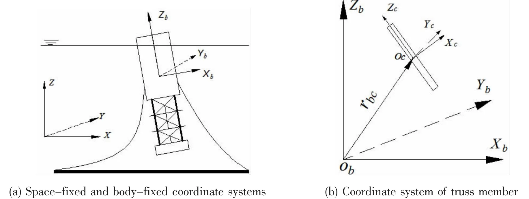
Fig.1 Coordinate systems of Truss Spar
1.2 Equations of the Truss Spar
In present study,the Truss Spar is assumed as a rigid body,and its motions are defined by a set of nonlinear equations given below:


The subscript G denotes the gravity term;M is the term due to mooring loads;H-term comes from hydrodynamic and hydrostatic pressure.
1.3 The hydrodynamic loads on the Truss Spar
The wave loads on the Spar hull is divided into two parts,e.g.the inviscid loads and drag force.The inviscid part on the hull including hard tank and truss structures is calculated by a slender formulation[19],which is composed of three parts:the transverse forces on per unit length,the immersed end loads and wave surface part.For completeness,the formulations are summarized below.
The transverse force on unit immersed length is given by:

The immersed end loads are expressed as:

where p includes static water pressure and the incident wave hydrodynamic pressure.The static water part and the integrationalong the centerline of the member is the buoyancy of the body in water.
Wave surface hydrodynamic pressure is given by:

where φ is the acute angle between the axis of the slender member and the normal vector of the undisturbed wave surface,andis the unit vector in intersection point.The drag force don the hull of the Spar,it is estimated by a squared velocity formula of Morison equation.
As for the hydrodynamic loads on hard tank,is composed of integration dfrom immersed end to top point of wetted length,But for truss member,there is a little difference due to excluding wave surface force and relatively small immersed end loads. Thus its hydrodynamic force and moment are expressed by:

The hydrodynamic force on heave plates and soft tank is calculated by the equation employed by Prislin et al[20].The total hydrodynamic forcecan be solved by summing of the corresponding wave loads of different parts of Truss Spar,including hard tank,truss structures, heave plates and soft tank.
1.4 The mooring loads on the Truss Spar
In present study,the taut mooring line is modeled as an elastic rope that withstands spring force,damping forces and hydrodynamic loads.The hull of the Truss Spar and each mooring line are coupled at fairleads.The mooring force and its moment of themooring line are expressed by:


In hydrodynamic calculation of mooring line,one of key tasks is to solve velocity and acceleration of points of mooring line.Several methods have been proposed.Huang[23]treated mooring cable to be lump-mass-and-spring model and velocity and acceleration of point in cable are evaluated by solving motion equation of discrete lump mass,whereas,in Ref.[15],they solved a linear momentum conservation equation from slender rod theory to decide mooring line’s velocity and acceleration vectors.An equilibrium equation is employed by Jeon et al[24]to compute kinematic quantities of catenary mooring cable.In above research,they have to solve ordinary or differential equation by different numerical methods such as the finite difference or finite element scheme,to estimate velocity,acceleration and position vectors of mooring line,whereas in this study the mooring line’s velocitiesare estimated by:

1.5 Numerical implement
These Eqs,from(1)to(4),are a set of nonlinear equations.To successfully find the solution for Spar motionsthe following tasks need to be performed:
(1)Calculating the wetted length of the hard tank
This is equivalent to find the common point between the instantaneous wave surface and the centerline of the truss Spar.For this purpose,an auxiliary function is defined,which depends on the wave surface and the position/attitude of the Spar centerline.The detailed description can be found in Xu et al[18].
(2)Efficiently computing hydrodynamic loads on the hull of the Truss Spar
After the instantaneous wetted length is found,the hydrodynamic loads on the Spar hull are evaluated by the adaptive Simpson integral method.The characteristic of this integral method, as well known,is to double the number of the integral intervals for each iteration cycle before the error tolerance is met.If this integral method is used directly along the long wetted length of the hull element of the Spar,the computational time will be unnecessarily increased since it does not reflect the fact that the hydrodynamic pressure on the hull decays exponentially along the water depth.To avoid it,the wetted length is divided into several parts and the adaptive Simpson integral method is applied for each part separately.
(3)Dealing with the coupling between the Spar and mooring lines

Fig.2 Flow chart of numerical procedure
(4)Solving motion equations.
The motion equations are solved by the Runge-Kutta-Fehlberg method in time domain. In the method,the time step is adaptive and at each step the tolerance error of the result is assessed by the difference()ε of its fifth-order solution and embedded fourth-order approximate result.If ε is larger than the specified tolerance error,the step size will be decreased by a scaling factor to do recalculation.The flow chart of this procedure is summarized in Fig.2, where,tein the chart is the final time specified for the numerical calculation.
2 Model test
2.1 The truss Spar model
The model used in this work has main features of a typical Truss Spar,with hard tank,truss structures,heave plates and soft tank.The details of the model are sketched in Fig.3 and summarized in Tab.1.The mooring system of the model consists of four same taut mooring lines. Each mooring line is made up of a spring and a nylon rope.The deformation of the mooring lines is mainly provided by springs.

Fig.3 Sketch of Truss Spar model(front view and top view,unit:mm)
2.2 Wave basin and measurement equipments
The Truss Spar model test was carried out in the wave tank of HEU(Harbin Engineering University).The tank is 108 meters long,7 meters wide and water is 3.5 meters deep.At one end of the tank,it is equipped with a hydraulically driven-flap wave maker,being able to generating waves with a maximum height of 0.4 meters and the wave periods from 0.4~4 s.At the other end,there is a beach to reduce the reflection waves.A steel frame is designed to hold the Spar model.On the top of the frame,one tension transducers is deployed to record the changes of tension from 1#mooring line.To make mooring lines connect with the top of the frame,four leading wheels are fixed at the lower part of the vertical frames.The motions of the Truss Spar model were measured by an optical measuring system(QUALISYS).Before starting the measurement,three markers radiating infrared light are fixed on the top of the model.When a test begins,a camera will capture markers’trajectory to record motions of the Truss spar model.The sample rate is 30 Hz.The experiment setup is sketched in Fig.4(a).

Fig.4 Setup of the tank and model(unit:mm)

Tab.1 Principal particulars of Truss Spar model

Tab.2 Wave parameters
2.3 Experiment program
This model test is composed of two parts.One is the free decay test,which aims to estimate the natural periods of motions of the Truss Spar model.The second part is to measure motions and mooring tensions of the Truss Spar model in regular waves.The angle between the incoming wave and the coordinate system of the model motion is set at 225°.These configurations are illustrated in Fig.4(b).When the incoming wave comes from 225°with respect to the X-axis of the coordinate system,the Spar model will move with six degrees of freedom.The wave parameters in experiment are listed in Tab.2.In the table,the wave amplitudes(from 1~11)are the average values recorded from wave probes.Those cases with star mark in the last three rows of Tab.2 denote that these wave states are not carried out in model test.However, those cases are performed by this numerical calculation.
3 Result and discussion
3.1 Free decay tests in the wave tank
In free decay tests,the Spar model is given an initial displacement and then subsequent motions are recorded.From those recorded motions of time history curve,the average natural periods of Spar model are estimated by time histories of motions.The surge natural period is 12.66 s.The heave and pitch periods are 2.6 s and 3.04 s,respectively.The natural period of surge motion is significantly larger than the natural periods of other two motions.This is mainly because the mooring tension is the only restoring force in the surge motion and is relatively small,compared with the restoring force/moment for heave and pitch motions,for which thebuoyancy force/moment provides a significant part of restoring force/moment besides mooring loads.
3.2 Comparison between numerical results and experimental data in time domain
The numerical method described above is applied to predict the motions and mooring tensions of the Truss Spar model,and motions and mooring tension from this calculation are compared with their corresponding results of model test.In the numerical calculation,a cosine taper function is employed to reduce the transient effect by wave forces on the structure in starting time stage,and the tapering period is 12 s in this study.

Fig.5 Comparison of time history of surge motion with T=1.8 s and A=26.5 mm
The hydrodynamic coefficients for hard tank and truss elements employed by all cases in numerical calculation are determined by using experimental results[24].Based on the experimental results,the added mass coefficient is close to 1.0(i.e.1+Cm=2.0 in the reference)with the KC number being less than about 3.0,whereas the drag coefficient behaves sensitive to the KC number.In this research,the KC number varies in the range of 0.384 for the hard tank and 4.89 for the truss elements.Thus for the hard tank,its added mass coefficient is chosen as 1.0 and its drag coefficient is determined by using experimental results in Chaktabarti[25].It is noted that since the KC number is relatively small compared with the values of the model tests, the drag coefficients determined in this way are based on extrapolation and so may not be accurate.However,the ratio of inertia to drag loads is about 1.98%estimated by using the following equation[25]and taking CDas 1.2 and Cmas 1.0

where FDis drag force from the squared term of fluid velocity and FIis inertia loads.This indicates that the loads on the hard tank are significantly dominated by inertia force and so small error in the drag coefficient does not necessarily lead to large error in estimating overall loads and motions of the SPAR.
The hydrodynamic coefficients of truss elements are also obtained by using the results in the above reference.They are relatively more accurate as their KC numbers and Re numbersboth fall into the model testing range of the reference,and so do not need the extrapolation and more accurate.For the hydrodynamic coefficients of mooring lines,the normal added mass and drag coefficients are selected as 1.15 and 1.2 as suggested by Tahar and Kim[15]while the tangential added mass and drag coefficients are chosen to be 0.2 and 0.17,respectively,similar to those used by Nakajima et al[27].

Fig.6 Comparison of time history of sway motion with T=1.8 s and A=26.5 mm

Fig.7 Comparison of time history of heave motion with T=1.8 s and A=26.5 mm

Fig.8 Comparison of time history of roll motion with T=1.8 s and A=26.5 mm
The numerical and experimental time histories of motions for the case with the incident angle of 225°,the wave period(T)of 1.8 s and wave amplitude(A)of 26.5 mm are compared in Figs.5-9.The mooring tension of 1#mooring line is demonstrated in Fig.10.As indicated above,with this configuration,the Spar has motions of six degrees of freedom but it is found that its yaw motion is very small compared to other five motions and so not plotted here.
From Figs.5-9,it can be found that motions from numerical calculation have almost the same changing trend compared with their experimental results,although slight difference still exists.Good agreement is also observed from time history of mooring tension in Fig.10.The small differences may from unsteady wave at the beginning stage and the numerical calculation not being absolutely identical to the experimental case.At the same time,it also can be seen that surge(sway)motion takes relatively longer time,to reach their steady-state motions, than time taken by pitch motion.Therefore,when studying the steady-state motions of surge or sway,enough time,not only for numerical simulation but also for experimental measurement, is necessary.

Fig.9 Comparison of time history of pitch motion with T=1.8 s and A=26.5 mm

Fig.10 Comparison of time history of mooring tension in 1#mooring line
3.2 Comparison between numerical result and model test data in frequency domain
To further validate this method,numerical results solved by this research are compared with their experimental data in frequency domain.The amplitude spectra of results concernedare calculated by Fourier transformation,and then they will be changed into corresponding RAOs.The specific results are discussed as follows:
The RAOs(Response Amplitude Operators)of the Truss Spar model in different wave states are obtained by model tests and numerical calculations.In this paper,the RAO of motions is defined as the ratio of the amplitude of each motion and wave amplitude.When waves come from 225°,the Truss Spar will undergo the motions with six degrees of freedom but in the following discussion only surge,heave and pitch motions are focused and the other comparison results of motions also have similar results,for brevity they are not given in this paper. The RAOs of them are shown in Figs.11-13.
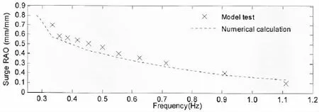
Fig.11 Surge RAO of the Truss Spar model

Fig.12 Heave RAO of the Truss Spar model

Fig.13 Pitch RAO of the Truss Spar model
From these figures,one can see that the RAO of surge monotonically increases with the decrease of wave frequencies while the RAOs of other two motions will reach a maximal point. That is because the natural frequency of surge is very small(near to 0.08 Hz as indicated free decay test)whereas the natural frequencies of other two motions are in the range of 0.3-0.4 Hz. Generally,the numerical and experimental results have a good agreement in all the figures.Specifically,the numerical results have a similar trend to these obtained by model tests.The maximum error between them is about 10%.As one could see from Figs.11-13,the larger error occurs in a range of frequency,lower than 0.4 Hz and higher than 1.0 Hz.There are various reasons for this.One of them would be due perhaps to the values of drag and inertia coefficients in numerical simulation may not be the exact same as the model would have in the model tests.In addition,some discrepancies,between numerical pitch motion and its tested results,are still found around natural frequency of heave,which may be because of coupled interaction of pitch and heave.If one Spar has large heave motion,its pitch motion will become instability and demonstrate nonlinear behaviors.Some evidences could be seen in research of Shen et al[28].The larger difference at higher wave frequencies or shorter waves may indicate that diffraction analysis,rather than slender theory,may be required to improve the numerical results.Nevertheless,the numerical results largely reflect the main features of the experiments results.
The dimensionless RAO of mooring tension is defined as the tension amplitude divided by ρgAD2,where,ρ is the water density;A and D represent the corresponding wave amplitude and the diameter of the hard tank,respectively.The corresponding RAO of line 1#is plotted in Fig.14.
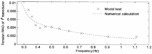
Fig.14 RAO of 1#mooring line of the Truss Spar model
From tension results of mooring line in waves,it can be seen that the RAO of tension also decrease with the increase of wave frequency.However,the change rate of the tension RAO becomes small when the wave frequency goes up,especially at the frequency larger than 0.9 Hz where the change rate is almost zero and the RAO tends to be a constant.The variation of RAO in largely follows the trend of the surges,which indicates that RAO of mooring line are strongly correlated with their surge motion.Overall,although comparison between the numerical calculation and the model test displays some discrepancy in the vicinity of the natural frequencies of heave and pitch motions,they are close to each other.
4 Conclusions
This paper presents a numerical method for evaluating the Truss Spar motions developed on the basis of our previous work but the mooring lines are modeled as elastic ropes compris-ing of spring and damper,and they withstand hydrodynamic loads.The hydrodynamic forces/ moments on hard tank and truss elements are estimated by slender formulation.However,it includes the nonlinear terms,such as point forces and divergent forces,which were usually ignored in literature but may play an important role as discussed in our previous publications. The motions of the Truss Spar are found by solving a set of fully nonlinear equations in a time domain,which include six degrees of freedom.
Model tests of a truss Spar were carried out in the wave tanks and some results are presented in this paper.The comparison between numerical results and experimental ones demonstrates that the numerical results agree reasonable well with the experimental data in a range of frequency if hydrodynamic coefficients used in calculation are carefully selected.Although the results are shown only for linear regular waves,the method has no barrier to be applied for nonlinear waves or irregular waves.
Acknowledgements
The authors would like to acknowledge financial support of Chang Jiang Scholarship.
[1]Bangs A S,Miettinen J A,Mikkola T P J,et al.Design of the Truss Spars for the Nansen/Boomvang field development[C]// Offshore Technology Conference.Houston,Texas,2002:841-853.
[2]Zhang Fan,Yang Jianmin,Li Runpei,et al.Coupling effects for cell-truss spar platform:Comparison of frequency-and time-domain analyses with model tests[J].Journal of Hydrodynamics,Ser.B,2008,20(4):424-432.
[3]Sun Mingyuan,Huang Weiping.A new concept of Spar in deep water and its hydrodynamic performance under internal wave[C]//Proceedings of 22nd International Offshore and Polar Engineering Conference.Rhodes,Greece,2012:975-982.
[4]Wang Ying,Yang Jianmin,Hu Zhiqiang.theoretical research on hydrodynamics of a geometric spar in frequency-and time-domains[J].Journal of Hydrodynamics,Ser B,2008,20(1):30-38.
[5]Falcão A F.Wave energy utilization:A review of the technologies[J].Renewable and Sustainable Energy Reviews,2010, 14(3):899-918.
[6]Ye Xiaorong,Gao Zhen,Moan Torgeir,et al.Comparison of numerical and experimental analyses of motion response of a spar-type floating offshore wind turbine in waves[C]//24th International Ocean and Polar Engineering Conference.Busan,Korea,2014:390-397.
[7]Agarwal A K,Jain A K.Dynamic behavior of offshore spar platforms under regular sea waves[J].Ocean Engineering, 2003,30(4):487-516.
[8]Kurian V J,Montasir,O A A,Narayanan S P.Numerical and model test results for truss spar platform[C]//Proceedings of the International Offshore and Polar Engineering Conference.Osaka,Japan,2009:99-104.
[9]Ma Q W,Patel M H.On the non-linear forces acting on a floating spar platform in ocean waves[J].Applied Ocean Research,2001,23(1):29-40.
[10]Kim M H,Ran Z,Zheng W.Hull/mooring coupled dynamic analysis of a truss spar in time-domain[C]//Proceedings of the International Offshore and Polar Engineering Conference.Brest,France,1999:301-308.
[11]Yang M,Teng B,Ning D,Shi Z.Coupled dynamic analysis for wave interaction with a truss spar and its mooring line/riser system in time domain[J].Ocean Engineering,2012,39(0):72-87.
[12]Kim M H,Chen W.Slender-body approximation for slowly-varying wave loads in multi-directional waves[J].Applied O-cean Research,1994,16(3):141-163.
[13]Montasir O A,Kurian V J.Effect of slowly varying drift forces on the motion characteristics of truss spar platforms[J].O-cean Engineering,2011,38(13):1417-1429.
[14]Jameel M,Ahmad S,Khaleel M,et al.Fully coupled nonlinear dynamic response of spar platform under random loads [C]//22nd International Offshore and Polar Engineering Conference.Rhodes,Greece,2012:1004-1011.
[15]Tahar A,Kim M H.Coupled-dynamic analysis of floating structures with polyester mooring lines[J].Ocean Engineering, 2008,35(17-18):1676-1685.
[16]Qu Yan,Song Zhijun,Teng Bin,et al.Dynamic response of SPAR in internal solitary waves[C]//Proceedings of the International Conference on Offshore Mechanics and Arctic Engineering.Rotterdam,Netherlands,2011:347-354.
[17]Chitrapu A S,Saha S,Salpekar V Y.Time-domain simulation of spar platform response in random waves and current[C]// Proceedings of the International Conference on Offshore Mechanics and Arctic Engineering.Lisbon,Portugal,1998:1-9.
[18]Xu G,Ma Q W,Sun L.Numerical investigations on truss SPAR motion in waves[C]//20th International Offshore and Polar Engineering Conference.Beijing,China,2010:508-513.
[19]Rainy R C.Slender-body expressions for the wave load on offshore structures[C].Proceedings of The Royal Society of London,Series A:Mathematical and Physical Sciences,1995:391-416.
[20]Prislin I,Blevins R D,Halkyard J E.Viscous damping and added mass of solid square plates[C]//17th International Conference on Offshore Mechanics and Arctic Engineering.Lisbon,Portugal,1998:7-17.
[21]Raman-Nair W,Baddour R E.Three-dimensional dynamics of a flexible marine riser undergoing large elastic deformations[J].Multibody System Dynamics,2003,10(4):393-423.
[22]Chen X,Zhang J,Johnson P,et al.Dynamic analysis of mooring lines with inserted springs[J].Applied Ocean Research, 2001,23(5):277-284.
[23]Huang S.Dynamic analysis of three-dimensional marine cables[J].Ocean Engineering,1994,21(6):587-605.
[24]Jeon S H,Cho Y U,Seo M W,et al.Dynamic response of floating substructure of spar-type offshore wind turbine with catenary mooring cables[J].Ocean Engineering,2013,72(0):356-364.
[25]Chakrabarti S K.Loads and responses[M].Handbook of Offshore Engineering,London:Elsevier.Ltd,2005:133-196.
[26]Molin B.Hydrodynamique des structures offshore(In chinese)[M].Beijing:National Defense Industry Press,2012:110-112.
[27]Nakajima T,Motora S,Fujino M.On the dynamic analysis of multi-component mooring lines[C]//Offshore Technology Conference.Houston,Texas,1982:105-110.
[28]Shen Wenjun,Tang Yougang,Gao Feng,et al.Study on the nonlinear dynamic characteristics of a Truss Spar[C]//24th International Ocean and Polar Engineering Conference.Busan,Korea,2014:1014-1018.
桁架式Spar平台在波浪中的运动预报与实验测量
许国春1,马庆位1,2,段文洋1,马 山1
(1.哈尔滨工程大学 船舶工程学院,哈尔滨150001;2.伦敦城市大学 工程与数学科学学院,英国 伦敦 EC1V 0HB)
基于细长体水动力公式和刚体全非线性运动方程,以及桁架式Spar平台主体与其锚泊系统相互耦合的力和位移边界条件,建立了桁架式Spar平台在波浪中的运动响应预报模型,对其在波浪中的运动和锚泊力进行了预报。通过运动光学测量系统和拉力传感器在哈尔滨工程大学水池对Spar平台模型在波浪中的运动和锚泊力进行了测量。数值预报结果和实验测量进行了比较,结果表明二者符合得很好。
桁架式Spar平台;细长体公式;运动;模型实验;锚泊载荷;波浪
U661.7
:A
许国春(1985-),男,哈尔滨工程大学博士研究生;
U661.7
A
10.3969/j.issn.1007-7294.2016.03.006
1007-7294(2016)03-0288-18
马庆位(1955-),男,伦敦城市大学&哈尔滨工程大学教授,博士生导师;
段文洋(1967-),男,哈尔滨工程大学船舶工程学院教授,博士生导师;
马 山(1976-),男,哈尔滨工程大学船舶工程学院教授。
Received date:2015-11-04
Biography:XU Guo-chun(1985-),male,Ph.D.candidate of Harbin Engineering University,xuguochun@hrbeu.edu.cn;
MA Qing-wei(1955-),male,professor of Harbin Engineering University&City University of London;
DUAN Wen-yang(1967-),male,professor/tutor of Harbin Engineering University.
猜你喜欢
杂志排行
船舶力学的其它文章
- Load-Compression Relationships of Bonded Rubber Ring
- Three Dimension Electromagnetic-Thermal-Mechanical Coupling Finite Element Model for High Frequency Induction Mobile Heating Formation of Steel Plate
- Fatigue Reliability Analysis for the Manned Cabin of Deep Manned Submersibles Based on the Unified Fatigue Life Prediction Method
- An Engineering Method to Predict Fatigue Crack Propagation Life for Marine Structures
- Experimental Studies of Failure Behavior and Strength of H Beams with Stiffened Web Openings under Compression and Bending Loads
- A Combination Mooring System and Mooring Characteristics Study