Coupled CFD/RBD Modeling for a BasicFinner Projectile with Control
2016-05-12KeXiChaoYanYuHuang
Ke Xi, Chao Yan, Yu Huang
(1. Research Institute of navigation and Control Technology, Beijing 100089, China 2. School of Aeronautic Science and Engineering, Beihang University, Beijing 100191, China)
Coupled CFD/RBD Modeling for a BasicFinner Projectile with Control
Ke Xi1,*, Chao Yan2, Yu Huang2
(1. Research Institute of navigation and Control Technology, Beijing 100089, China 2. School of Aeronautic Science and Engineering, Beihang University, Beijing 100191, China)
This paper introduces the development and application of an advanced time-accurate multidisciplinary technique for the prediction of unsteady aerodynamics and flight dynamics of maneuvering projectiles. The virtual flight simulation of a basic finner projectile has been investigated through coupling solving procedure of unsteady Navier-Stokes equations, rigid-body six degree-of-freedom motion equations and control law. The flow solver uses a finite-volume method based on structure grid with dual time stepping. Additionally, a feedback controller is required for the control surfaces to attain the commanded deflections, and the overset Chimera method is used to simulate relative motions. The predictions show that the gains for the controller must be correctly selected to obtain the proper response. Simulation results show that the virtual flight simulation platform developed here is capable of solving the complicated unsteady flows with moving boundary, has a strong promotion to engineering application.
Computational Fluid Dynamic, Basic finner, Virtual flight simulation, Unsteady flow, Feedback control
0 Introduction
Agility and maneuverability are always the basic requirements of advanced air combat weapons. In order to meet the requirements of future air combat, aircraft design has been pushed towards the expansion of flight envelopes into extreme conditions (high angle of attack) and aggressive maneuvers with high angular rates, involving strongly nonlinear aerodynamic phenomena, when the asymmetric vortical flow would dominate the flow field. The vehicle would typically operate in the post-stall regime of the lifting surfaces. The dynamic and time-dependent effects of the nonlinear flow characteristics, including flow separation, vortex shedding, and vortex lag effects, contribute significantly to the behavior and maneuvering capability of the vehicle. The basis of conventional flight mechanics models is a coefficient based des-cription of the aerodynamics, with the coefficients (stability derivatives) being obtained from experiment or computational fluid dynamics (CFD), and it is incompetent to describe some rather complex aerodynamic phenomena which incorporates significant hysteresis. There is a need
to develop a high-fidelity model which is able to replicate the actual free flight. In the past 30 years, with the rapid growth of the computational resources, CFD has achieved a significant progress and CFD is considered to be very close to its maturing stage in steady flow computation at designed conditions. The next target of CFD is numerical simulation of maneuvering vehicles through multidisciplinary computations [1].
In principle CFD can produce the aerodynamic inputs but also, through a coupling procedure with rigid body dynamics (RBD) and control, can simulate a rigid motion response directly. CFD based virtual flight simulation is such a technology which integrates multidisciplinary design method. The basic concept of virtual flight test which originates from wind tunnel is that the vehicle will move freely, the control surfaces will be able to real time control according to the flight control systems demand, and the aerodynamic loading and motion parameters are obtained simultaneously during the simulation. The CFD based virtual flight simulation has the potential to provide detailed fluid dynamic understanding of the unsteady aerodynamics processes involving the maneuvering flight of modern air combat weapon systems. This multidisciplinary design technology will be able to explore the coupling mechanism of the aerodynamics/flight dynamics, resulting in reduced development costs and higher performance weapons.
A lot of progress has been made recently with the coupled CFD/RBD procedure for prediction of unsteady aerodynamics and flight dynamics of projectiles [2-6]. Control actions and their aerodynamic phenomena have also been extensively studied. The most remarkable subjects are the effect of different actuation schemes, such as jet actuators [7], elastic deformation [8] and motion of control surfaces. Observing independent studies that relate control and RBD to aerodynamics, the natural step is to link them all in a comprehensive, integrated application [9-11]. With the increasing capacity of computers, coupling of CFD with motion dynamics and control can represent an important tool for the design of an aircraft’s geometry and its guidance and control algorithms, as it can be employed to obtain aerodynamic models, evaluate performance during control actions and compute virtual fly-outs.
With this in mind, this paper presents efforts towards such high-fidelity flight dynamic models. The intention here is not to investigate complex flight mechanics behavior, but to describe the development of a tool which can be used for this purpose. The methodology herein proposed uses CFD to estimate the transient flow field around the vehicle; uses the vehicle’s equations of motion to calculate its movement in 3-dimensional space; and a controller which uses the body’s motion state to command a deflection of its control surfaces. This information is then fed back to the CFD domain to restart a new flow field and advance in the simulation of a fly-out.
1 Computational Methodology
1.1 Computational Fluid Dynamics
In this study, the MI-CFD flow solver was used to compute the flow field around the vehicle. MI-CFD is developed under the leadership of Prof. Yan at Beihang University [12]. MI-CFD is a second-order, cell-centered, finite-volume Navier-Stokes (N-S) flow solver. The complete set of three-dimensional time-dependent Reynolds-Averaged Navier-Stokes (RANS) equations is solved in a time-accurate manner for simulations of unsteady flow fields.
The conservation form of the 3-D dimensionless, unsteady, compressible, RANS equations in body-fitted coordinates is as follows:
(1)
whereQis the vector of conservative variables,F,GandHare the convection flux vectors,FV,GVandHVare the viscous flux vectors,tstands for time,Re∞theReynoldsnumberoffreestream.
MI-CFDiscapableofusingseveraldifferentfluxschemes,timeschemes,limitersandturbulencemodels.Inthisstudy,theRoe’sFDSschemeisused,aswellastheminmodlimiter.Two-equationshear-stress-transport(SST)turbulencemodelisadoptedforthecomputationofturbulentflows.Dualtime-steppingisusedtoachievethedesiredtime-accuracy.Open-MPparallelstrategyisem-ployedtospeedupcomputation.Thedetailscanbefound,forinstance,inRef.
[13].
1.2 Chimera Technique
The chimera technique, as implemented in MI-CFD, provides the capability to simulate large amplitude control-surface deflections. The overset grid gets rid of the restriction of structured grids’ topology and thus, for arbitrary complex geometries, grids with different topologies can be generated independently. The technique is based on creating overlapping grids to handle a time-dependent relative motion of different geometries. In the overlapping grids concept, there are two major procedures involved in establishing intergrid communications. The first procedure is hole cutting (automatic or manual). For the cases presented in this paper, automatic hole cutting is used. The second procedure is the identification of interpolation stencils, which involves a search of donor cells for all intergrid boundary points. The search algorithm is based on a state-of-the-art alternating digital tree (ADT) data structure [14].The ADT data structure optimizes the search operations to O(lgN/lg2) as opposed to the total number(N) of elements in the computational domain. For the moving multi-body simulation presented in this paper, an efficient method which is known as dynamic overset is used since the overset grid assembly should be performed at every time step.
1.3 Coupled CFD/RBD/GNC Procedure
A coupled CFD/RBD procedure is needed for the simulation of virtual fly-out of projectiles. The CFD/RBD simulation combines a rigid six degree-of-freedom (DOF) flight dynamic model with a three dimensional, time-accurate CFD simulation. This combination is formed by allowing the RBD dynamic equations to be integrated forward in time, while the aerodynamic forces and moments are generated by CFD. The reference frames used for the CFD/RBD simulation are the standard inertial and body frames, and are depicted in Fig.1 below. The inertial frame,i, is fixed to the ground, and oriented withyipointingupwards.Thebodyframeisfixedtothecenterofmassoftheprojectile,andisorientedsuchthatxbpointsthroughthenoseoftheprojectileandtheotherunitvectorsformaright-handedsystem.TheprojectileorientationisdefinedbytheuseofEuleranglesinthestandardaerodynamicsequenceofrotations.Thus,therigidbodystatecontaintheinertialprojectilecenterofmasslocation, (x,y,z), the Euler angles, (φ,θ,ψ),thebodyframecomponentsoftheprojectilecenterofmassvelocity(u,v,w), and the body frame components of the projectile angular velocity (p,q,r).

Fig.1 Reference frame definition.
The RBD equations used here are the standard equations for the center of mass of a rigid projectile. They are given in the equations below.
where the forces (Fx,i,Fy,i,Fz,i)andthemoments(Mx,My,Mz)intheaboveequationsrepresentthetotalforcesandmomentsappliedtotheprojectile.Thenonlineardifferentialequationscanbesolvedusingafourth-orderRunger-Kuttamethod.Thedual-EulermethodisusedtoovercomethesingularityofEulerequation[15].
Forsimulationsofguidedcontrolmaneuvers,acoupledCFD/RBD/GNCprocedurehasbeendevelopedbyintegratingGNCpartintothecoupledCFD/RBDmethod.Theaddedelementofthiscouplingistheguidance,navigation,andcontrolaspect(GNC).TheGNCcapabilityemploysafeedbackcontroller.Asthecontrolalgorithmisnottheprimarybasisofthisresearchasimpleproportional-integral-derivative(PID)controllerisused.PIDcontrollerisalinearcontrollerbasedonthesimpleestimationofthepast,presentandfuturemessage.Duringtheflight,thecontrolofthevehiclecanbeachievedinmanyways,e.g.,withcontrolsurfacesorpulsejets.Inthepresentpaper,onlytheformercontrolmechanismisstudied.
Fig.2depictstheschematicofthePIDcontroller.αeisthedesiredstate,αtisthereal-timestate,δristhecontrolsurfacedeflection.PIDcontrollerworksviasomefundamentalcontrolelementssuchassummers,comparators,gainsandintegrators.Ithastheform
(3)
Wheree(t)=αe-αtisthedeviation,u(t)isthecontrolvariable,Kp,KiandKdarethecontrolgains.
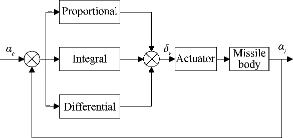
Fig.2 Schematic of the PID controller.
InthecoupledCFD/RBD/GNCprocedure,theaerodynamicforcesandmomentsarecomputedateverysingletimestepintheCFDsolverandtransferredtotheRBDparttopredictthenewflightstates.Theflightcontrolsystem(FCS)providesthecontrolvariablesbasedonagivenFCSdesign.TheFCSdesignallowsformodelingofbothcontrolledandprescribedmotions.Thecontrolstrategyusesthevehicle’smotionstatevariablesasfeedback,andmustdefinethedesiredattitudes.Controlalgorithmisworkedtodefinethecommandeddeflectionineachcontrolsurface.TheoutputofRBDstateandthecontrolvariablesaretransferredtotheCFDflowsolverwhichthencomputestheaerodynamicforcesandmomentssubjecttotheseRBDstateandcontrolvariables.
ThecouplingoftheCFD/RBDprocedureisalooseone.Fig.3illustratesthemethodology,whichcanbesummarizedasfollows:

Fig.3 Diagram of the coupled process.
1)Withtheinitialmotionoftheobject,thesteady-stateflowfieldiscomputedthroughCFD.
2)Aerodynamicforcesandmomentsareobtainedthroughintegration.
3)RBDmodelissolvedandnumericallyinte-gratedonetimestepforwardtofindthenewmotionstate.
4)Controlalgorithmisexecutedtodefinethecommandedanglesineachcontrolsurface.
5)Oversetgridisusedtoaccountforrelativemotionandthedomain’snewboundaryconditionsaredefined.
6)Dual-time-steppingmethodisusedtoadvancethetimesteptoobtaintheupdatedflowfield.
7)Returntostep2andrepeatuntildesiredphysicalsimulationtimeisreached.
2 Computational Model
The test case for the current simulations is the Basic Finner projectile. The model is a generic missile configuration which consists of a cone-cylinder with four rectangular fins (see Fig.4) [16]. The length of the projectile is 10 calibers and the diameter is 30 mm. The conical nose is 2.84 calibers long and is followed by a 7.16 caliber cylindrical section. Four fins are located on the back end of the projectile. Each fin is one caliber long, and has a thickness of 0.08 calibers. The center of gravity (CG) was located at 5.5 calibers from the nose of the projectile. Table 1 shows the physical properties of the model.
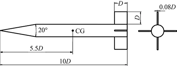
Fig.4 Schematic of the basic finner.
A structured overset computational mesh (see Fig.5) was generated for the projectile. In general, most of the grid points are clustered in the boundary-layer, fins, and the wake regions. The boundary layer spacing near the wall was selected in order to achieve ay+value of 1.0. The mesh was generated using the Gridgen V15.17 grid-generation software developed by Pointwise Inc. The main body and four rectangular fins were gridded separately and this significantly reduced the restrictions on grid generation. The grids are then overset with each other using a Chimera method. The total number of grid points in this case is approximately 5 million. This Chimera procedure requires proper transfer of information between the main body mesh and the fins meshes. However, the advantage is that the individual grids are generated only once and the Chimera procedure can then be applied repeatedly as required during motion. There is no need to generate meshes at each time step during the maneuvers.
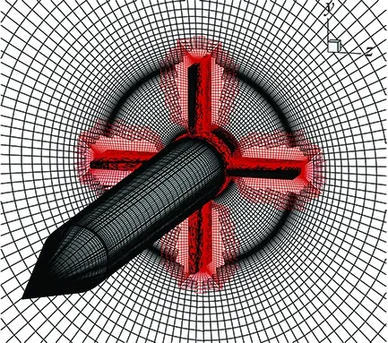
Fig.5 Overset grid of the model.

PhysicalpropertiesCalueLength/m0.3Diameter/m0.03Mass/kg1.58Ixx/(kg·m2)1.92×10-4Iyy,Izz/(kg·m2)9.785×10-3CG(fromnose)/m0.165
3 Results and Discussion
This paper pursues the high-fidelity assessment of the flight dynamics. Therefor a virtual flight simulation platform coupling CFD and RBD including control surface motion capabilities was developed. Demonstration of the coupled CFD/RBD technique has been achieved using an angle of attack control maneuver. The intention here is not to investigate complex flight mechanics behavior, but to describe the development of the tool, so we are only dealing with longitudinal motion. Besides, the translational motion is constrained.
Typically, a solution obtained in the steady-state mode serves as the starting solution for the coupled CFD/RBD run. The coupled run starts to deflect the fins in accordance with the control law or the controller. CFD results are obtained in a time-accurate manner.
For the computations presented here, the initial state of the projectile is fixed at zero degrees angle of attack, a height of 10 km and a flight velocity of Mach 2. The initial deflection angle of the elevator is supposed to be zero degree. The initial conditions represent the initial state of the projectile prior to a commanded maneuver.
3.1 Open-loop Simulations
Generally, the flying qualities include both controllability and stability. First we simulate the open-loop response of the projectile for different types of rudder control laws. We can have a comprehensive knowledge of the dynamic characteristics of the projectile from these simulations. After data are acquired, parameter identification techniques can be applied to the motion history to extract aerodynamic coefficients.
Given the four rudder control laws:
δe(t)=5°,t≥0
(4)
(5)
(6)
(7)
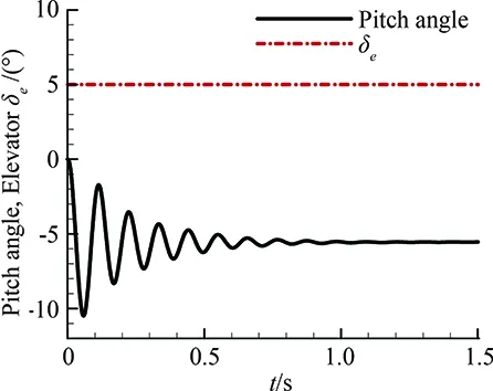
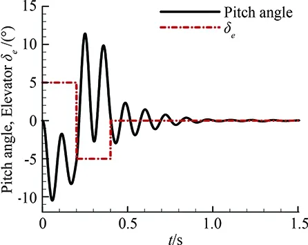
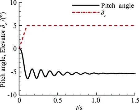
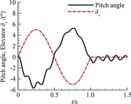
Formula(4)through(7)eachstandsforastep-rudder,adoubletrudder,atrapezoidalrudderandaharmonicrudder.Fig.6showsthecontrolsurfacesdeflectionsandpitchanglehistoriesoftheprojectileopen-loopsimulations.Thesimulationtimetakesonly1.5seconds.
TheequationofmotionfortheopenloopsimulationscanbewrittenasshowninEq.(8).

(8)
Thesecond-ordercharacteristicequationis
(9)

Eq.(8)reflectstheinherentdynamicbehaviorsoftheprojectile.TherighthandsideofEq.(8)whichstandsfortheroleoftheflightcontrolsystemwillchangethedynamicbehaviorsoftheprojectile.Whentherighthandsideisnotzero,namely,theflightcontrolsystemtakeseffect,theautonomoussystemchangesintonon-autonomoussystem.Thedynamicbehavioroftheprojectileisdeterminedbytheinherentcharacteristicsandcontrolsystemtogether.
(a) Step-rudder
(b) Doublet rudder
(c) Trapezoidal rudder
(d) Harmonic rudderFig.6 The response to different types of rudder deflections.
Forthestep-rudder,theanalyticalsolutionofthegoverningequation(Eq.(8))canbewrittenas:

(10)
Where
αtrim=-Cmδeδe/Cmα
(11)

Itusuallytakestheovershoot,peaktime,transitiontimeandoscillationfrequencytoassessthedynamicquality.Ingeneral,gooddynamicqualityrequiresnoobviousovershootoroscillationintransitionprocess,andtheprojectilequicklyreachesthedesiredstate.
Fig.6(a)showstheresponseofastep-rudder,whichrepresentsanextremecasewhenthevehicleisundergoingrapidmaneuverandtherudderanglerateisinfinity.Fig.6(b)showstheresponseofadoubletrudder,whichrepresentstheinstantaneousinterferencethevehicleencountered.Fig.6(c)showstheresponseofatrapezoidalrudder,whichrepresentsaslowmaneuvering.Ascanbeseenfromthefigure,theovershootisobviouslylessthanthatofstep-rudder.Fig.6(d)showstheresponseofaharmonicrudder,whichrepresentstheidealizedrepeatedmodificationprocess.Allthecomputationsindicateabothstaticallyanddynamicallystableconfiguration.Fromthesesimulations,wecanobtainthekeyfeaturesoftheprojectilesoastobepreparedfortheclosedloopsimulation.
3.2 Closed-loop Simulations
For a actual flight, the autopilot or flight control system will send control commands according to the flight state in real time, to make the vehicle stabilize in scheduled trajectory or maneuver to the desired state. Therefore, a feedback controller is needed. A simple proportional derivative control law is used for feedback control.
The elevator deflection angle is given by the equation below.
δe(t)=Kp(αd-α(t))+
(12)
ThecontrolgainsKp,KiandKdarechosenexperimentallytoobtainadesirabletimeresponseofthesystem.
Inreality,thecontrolfinsarelimitedinbandwidth.Assumethatthecontrolfinsreceivecontrolsignalseverytruddertime. And the physical time step used in CFD calculations is far less thantrudder. Again suppose that the deflections of the control surfaces are continuous and smooth duringtruddertime, rather than a step rudder. The smooth formula is as follows:
δ(t)=Δδ·(10λ3-15λ4+6λ5)
λ=t/trudder-int(t/trudder)∈[0, 1]
(13)
WhereΔδis the total deflection angle duringtruddertime.
Based on PID controller, a closed-loop angle tracking system was constituted to simulate a commanded maneuver.
The control command was that the projectile maneuvered from the initial state to five degrees angle of attack, and stabilized in this position.
The equation of motion for the closed-loop simulation is the same as Eq.(8), butδeisdeterminedasshowninEq.(12).
SubstitutingEq.(12)intoEq.(8)yields
(14)
AsEq.(14)explicitlyhasthetimevariable,itbecomesanon-autonomoussystem.Thedynamiccharacteristicofthevehicleisdeterminednotonlybytheinherentpropertiesbutalsobythecontrolsystem.Forthestaticallyordynamicallyunstablevehicle,thecontrolgainscanbeadjustedtomakethevehiclestable.
Thesignificantbenefitofthecoupledapproachisthattheinstantaneousaerodynamicforceandmomentarecomputedtodeterminetheresponseoftheprojectile.Thepredictedaerodynamicloadincludesalltherelevantinstantaneouseffects,includingcontrolsurfacesdeflections,deflectionrate,wakeandallotherinterferenceeffects.Asthesimulationresultsaresensitivetothecontrolgains,theparametricstudiesneedtobeperformedtodecidetheoptimalchoice.
Fig.7showstheresponsesfordifferentparameters.Theparametersarelistedontopofthefigures.Ontheleftsidearethetimehistoriesofangleofattack(blacksolidline)andelevatordeflectionangles(reddashdottedline),andtherightsideisthepitchrateversusangleofattack.Kp,Kdandtruddervary from case to case. The integral gain is not important since the system contains little steady state error, so the integral gain maintains as a constant.
As shown in Fig.7, initially the angle of attack is zero, starts to increase with the deflections of control surfaces. Under the effect of the controller, the system brakes in advance to prevent overshoot. The pitch rate begins to reduce while the angle of attack continues to increase. Finally, the projectile reaches the desired state after several adjustments. The phase portrait shows a stable spiral point structure. In general, good dynamic quality requires no significant overshoot or oscillation, and short transition time. We can compare the results of case A with case B to find how the derivative gain affects the dynamic behavior of the projectile. In the two cases, all the parameters are same exceptKd. We can find that the overshoot for case B (with smallerKd) is a little larger than the one for case A, and the maximum pitch rate follows the same tendency. In fact, the derivative gain helps the system brake in advance to prevent overshoot, and it works like damping coefficient, and it’s related to dynamic stability derivative. Also we can compare the results of case C with case D to find how the proportional gain affects the dynamic behavior of the projectile. From the two cases, we can find that the overshoot for case C (with largerKp) is a little larger than the one for case D, and the maximum pitch rate follows the same tendency. Besides, the transition time is a little longer for case C. The proportional gain is related to steerage. The speed of response can be faster by increasing the proportional gain, but the response can also be oscillatory or even diverge if the proportional gain is too large. From the results of case A and D, we can find that the overshoot is almost the same for the two cases, but the maximum pitch rate of case A is larger than that of case D. Obviously, larger pitch rate would be needed to reach the state in shorter time. But it is not a good idea to choose a value close to the natural frequency, or it will cause oscillation or even divergence.
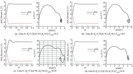
Fig.7 The responses for different parameters, angle of attack and elevator deflections histories, pitch rate vs. angle of attack.
Fig.8 shows the computed pitching moments as a function of time. Results obtained from all four cases are compared to each other. The maximum moment shows similar behavior with the maximum pitch rate.
To demonstrate the capability of the platform for the prediction of high angle of attack conditions, a new simula-tion is conducted. The new control command is that when the projectile reached five degrees angle of attack, and stabilized, then maneuvers to fifteen degrees angle of attack, and stabilized in the new position.
Fig.9 shows the responses of the projectile under new command. Fig.10 shows the phase portrait. As can be seen from the figures, high frequency oscillation appears when the projectile maneuvers from five degrees angle of attack to fifteen degrees angle of attack. This is probably caused by the nonlinear characteristic of the flow field due to the vortices flow at high angle of attack.

Fig.8 Computed aerodynamics pitching moments as a function of time.
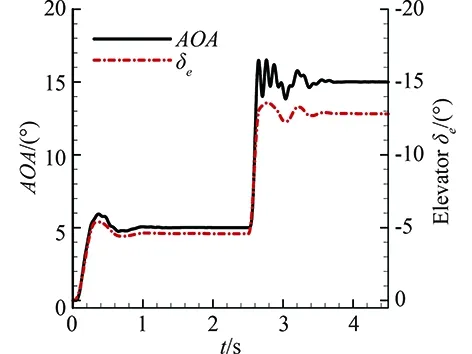
Fig.9 The responses under new command.
4 Conclusion and Future Work
This paper describes the development and application of a time-accurate coupled CFD/RBD multidisciplinary technique for prediction of un-steady aerodynamics and flight dynamics of maneu-vering projectiles.
Using this multidisciplinary approach, the time-dependent response of the Basic Finner projectile has been simulated. Simulation results show that the virtual flight simulation platform is capable of solving the complicated unsteady flows with moving boundary, can provide the data for the unsteady aerodynamic modeling, indicate the stability of aircraft and test flight control law, has a strong applicability to engineering application. Work is
currently on-going to simulate the full degrees of freedom of the virtual fly-out.
[1]Salas M D. Digital Flight: The last CFD aeronautical grand challenge[J]. Journal of Scientific Computing, 2006, 28(2/3): 479-505.
[2]Schütte A, Einarsson G, Raichle A, et al. Prediction of the unsteady behavior of maneuvering aircraft by CFD aerodynamic, flight-mechanic and aeroelastic coupling[R]. NATO RTO-MP-AVT-123-P-11,2005.
[3]Morton S A, Eymann T A, Lamberson S, et al. Relative motion simulations using an overset multimesh paradigm with Kestrel v3. AIAA 2012-0712[R]. Reston: AIAA, 2012.
[4]Sahu J. Virtual fly-out simulations of a spinning projectile from subsonic to supersonic speeds. AIAA 2011-3026[R]. Reston: AIAA, 2011.
[5]Prewitt N C, Belk D M, Shyy W. Parallel computing of overset grids for aerodynamic problems with moving objects[J]. Progress in Aerospace Sciences, 2000, 36: 117-176.
[6]Xi K, Ma L J, Yan C, et al. Numerical simulation of three-store ripple release using overset structured grid[J]. Physics of Gases, 2012, 7(4) : 75-79 (in Chinese).
[7]Jee S K, Lopez O D, Muse J, et al. Flow simulation of a controlled airfoil with synthetic jet actuators. AIAA 2009-3673[R]. Reston: AIAA, 2009.
[8]Michler A. Aircraft control surface deflection using RBF-based mesh deformation[J]. International Journal of Numerical Methods in Engineering, 2011, 88(10): 986-1007.
[9]Xi K, Yuan W, Yan C, et al. Virtual flight numerical simulation of the Basic Finner projectile with closed loop[J]. Acta Aeronautica et Astronautica Sinica, 2014, 35(3): 634-642 (in Chinese).
[10]Camargo J, Lopez O, Lleras N O. A computational tool for unsteady aerodynamic flow simulations coupled with rigid body dynamics and control. AIAA 2012-3034[R]. Reston: AIAA, 2012.
[11]Sahu J, Costello M, Montavo C. Development and application of multidisciplinary coupled computational techniques for projectile aero dynamics[C]//ICCFD7-4504, 2012.
[12]Fan J J, Yan C. Enhancement and application of overset grid assembly[J]. Chinese Journal of Aeronautics, 2010, 23: 631-638.
[13]Krist S L, Biedron R T, Rumsey C L. CFL3D User’s Manual[R]. NASA/TM-1998-208444, 1998.
[14]Bonet J, Peraire J. An alternating digital tree (ADT) algorithm for 3D geometric searching and intersection problems[J]. International Journal of Numerical Methods in Engineering, 1991, 31: 1-17.
[15]Huang X Q. The dual-Euler method for overcoming the singularity of Euler Equation[J]. Flight Dynamics, 1994, 12(4): 28-37. (in Chinese).
[16]Dupuis A D, Hathaway W. Aeroballistic range tests of the basic finner reference projectile at supersonic velocities. DREV-TM-9703[R]. Valcartier, Canada: Defense Research Establishment, 1997.
0258-1825(2016)02-0182-08
带反馈控制的基本带翼外形的耦合气动/运动数值模拟研究
席 柯1,*, 阎 超2, 黄 宇2
(1. 中国兵器工业导航与控制技术研究所, 北京 100089; 2. 北京航空航天大学 航空科学与工程学院, 北京 100191)
介绍了一种先进的、时间精度的多学科数值模拟平台的开发和应用,该平台可用于预测飞行器机动过程中的非定常气动特性和飞行力学特性。通过耦合求解非定常Navier-Stokes方程、刚体动力学方程及控制律,对基本带翼外形进行了虚拟飞行数值模拟研究。求解器采用基于结构网格的有限体积法,时间方法采用双时间步方法。使用反馈控制器获得舵偏控制指令,重叠网格方法用来模拟物体间的相对运动。模拟结果显示控制器的增益必须正确选择才能获得正确的响应。仿真结果表明本文发展的虚拟飞行数值模拟方法能够预测包含动边界的复杂非定常流动,具有较强的工程适用性。
计算流体力学;基本带翼外形;虚拟飞行;非定常流动;反馈控制
V211.3
A doi: 10.7638/kqdlxxb-2016.0005
*Research Assistant; cauchy86@163.com
format: Xi K, Yan C, Huang Y. Coupled CFD/RBD modeling for a basic finner projectile with control[J]. Acta Aerodynamica Sinica, 2016, 34(2): 182-189.
10.7638/kqdlxxb-2016.0005. 席柯, 阎超, 黄宇. 带反馈控制的基本带翼外形的耦合气动/运动数值模拟研究(英文)[J]. 空气动力学学报, 2016, 34(2): 182-189.
Received: 2015-12-15; Revised:2016-02-10
猜你喜欢
杂志排行
空气动力学学报的其它文章
- Computational Fluid Dynamicsin Europe, a Personal View
- The History of CFD in China
- Simulations of Transonic Flows withFriction and Heat Addition
- High Order Numerical Methods for LESof Turbulent Flows with Shocks
- Vorticity Dynamics and Control of Self-PropelledFlying of a Three-Dimensional Bird
- Residual Schemes Applied to an Embedded MethodExpressed on Unstructured Adapted Grids
