Multi-LeapMotion sensor based demonstration for robotic refine tabletop object manipulation task☆
2016-04-11HaiyangJinQingChenZhixianChenYingHuJianweiZhang
Haiyang Jin,Qing Chen,Zhixian Chen,Ying Hu,*,Jianwei Zhang
aShenzhen Institutes of Advanced Technology,Chinese Academy of Sciences,Shenzhen,China
bChinese University of Hong Kong,Hong Kong,China
cUniversity of Hamburg,Hamburg,Germany
Original article
Multi-LeapMotion sensor based demonstration for robotic refine tabletop object manipulation task☆
Haiyang Jina,b,c,Qing Chena,b,Zhixian Chena,b,Ying Hua,b,*,Jianwei Zhangc
aShenzhen Institutes of Advanced Technology,Chinese Academy of Sciences,Shenzhen,China
bChinese University of Hong Kong,Hong Kong,China
cUniversity of Hamburg,Hamburg,Germany
In some complicated tabletop object manipulation task for robotic system,demonstration based control is an efficient way to enhance the stability of execution.In this paper,we use a new optical hand tracking sensor,LeapMotion,to perform a non-contact demonstration for robotic systems.A Multi-LeapMotion hand tracking system is developed.The setup of the two sensors is analyzed to gain a optimal way for efficiently use the informations from the two sensors.Meanwhile,the coordinate systems of the Mult-LeapMotion hand tracking device and the robotic demonstration system are developed.With the recognition to the element actions and the delay calibration,the fusion principles are developed to get the improved and corrected gesture recognition.The gesture recognition and scenario experiments are carried out,and indicate the improvement of the proposed Multi-LeapMotion hand tracking system in tabletop object manipulation task for robotic demonstration.
LeapMotion sensor;Muti-sensor fusion;Tele-operative demonstration;Gesture recognition;Tabletop object manipulation
1.Introduction
For intelligent robots,tabletop object manipulation is one of the most common task.It combines the capabilities of the robot in vision,image procession,object recognition,handarm manipulation,etc.However,the real indoor environment is much more complicated than experimental scenarios.The vision of the robot sometimes can hardly provides enough information for successfully executing some difficult tasks, such as pick,place or assemble some small objects[1].In these cases,if two objects are too close to each other,it will be difficult to correctly segment them;moreover,some occlusion cases often occur in real indoor environment.So,teleoperative demonstration method is an efficient way to overcome these problems[2,3].
These demonstration methods have already been used on industrial robots for some years.For instance,the controller with buttons or a six-dimensional mouse are used to control the robot and tell the key positions and orientations,so that the robot can plan the trajectory and correctly reach each key position with desired orientations and perform a smooth movement[4].However,the interface of this kind of demonstration method is not efficient for an intelligent robotic system.And in most such systems,the robot only records position and orientations without interpreting gestures,so these systems are not applicable to more complex tabletop object manipulation tasks.A more natural method based on a kinesthetic interface is used for demonstration.One can drag the robotic arm to follow his actions,such as the researches on humanoid robots by Hersch et al.[5]and Hwang et al.[6]. However,this method also aims at the trajectory trackingrather than at gesture recognition.Furthermore,this is a typical contact control method in which a human works within the same environment as the robot.Therefore,it is hardly used in human-unfriendly environments.For this reason,noncontact tele-control methods are more appropriate for these situation.For example,some mechanical based[7-9],optical tracking based or vision based master-slave-device and teleoperation system[10-12]are developed for robotic systems. Comparing with the mechanical devices,the optical and vision tracking systems are lower cost and easier to be mounted in difference environment.
For hand gesture recognition,a highly ef ficient way is using data glove that can record the motion of each finger[13,14]; some kinds of data glove can even measure the contact force of a grasping or pinching action[15].However,beside the high cost of data glove,they lack the capability to track position of the hand.Therefore,extra approaches are added to track hand positions[16,17],such as inferred optical tracking [18],which also increases the complexity of the system.
Some scholars only use the vision based method for both the hand tracking and gesture recognition.But the performance of the gesture recognition is much effected by the lighting and background conditions[19-21].Thus,some aiding methods like skin color and pure color background are used to improve the recognition accuracy[22,23].Some other scholars use RGB-D data from Kinect for gesture recognition [24].However,the Kinect sensor is developed for body motion tracking,In the research of Kim et al.,it has been proved that the accuracy of hand motion tracking using Kinect is much lower than LeapMotion sensor,which is particularly designed for hand motion trac1http://www.leapmotion.com.king[25].
The LeapMotionsensor,developed by Leap Motion Inc., is a new non-contact finger/hand tracking sensor.It has a high tracking accuracy and provides plenty of software interface for pose and gesture recognition.Some preliminary studies have been carried out for robot manipulation.Zubrycki et al.use a LeapMotion sensor to control a 3- finger gripper[26],GuerreroRincon et al.develop a interface to control a robotic arm [27],Marin et al.report the first attempt to detect gestures from the data combination of LeapMotion and Kinect[28,29]. These use single LeapMotion for hand tracking and gesture recognition,however,due to the occlusion problem between fingers,single sensor can perform well only when the palm is with a ideal orientation.
In this paper,a multi-LeapMotion hand tracking system is developed to overcome the limitation of the aforementioned drawback of single LeapMotion.The tracking space and working area are analyzed to gain an appropriate setup for two LeapMotion sensors.With self-registration,a coordinate system are established.Based on the de finition of the element actions,an algorithm to calibrate the delay and combine the data from the two LeapMotion sensors is proposed to improve the stability for both the hand tracking and gesture recognition. To developed a tele-operative demonstration system,a Kinect sensor and a 7-DoFs(Degree of Freedoms)robotic arm with a 3-finger gripper are combined with the developed Multi-LeapMotion hand tracking system in ROS(Robot Operation System).2http://www.ros.org.Functional experiments are performed to indicate the results of combined hand tracking and gesture recognition. At the end,a scenario experiment is performed to show how this proposed system is used in a robotic system.
The rest of this paper organized as follow:the design and setup of Muti-LeapMotion hand tracking system is described in section II;the data fusion algorithm of the two sensors is shown in section III;in section IV introduces the scenario setups and experiments;at the end,some conclusion,discussion and future works are given in section V.
2.Design of the Muti-LeapMotion hand tracking system
2.1.Setups of the Muti-LeapMotion sensors
For high accuracy gesture recognition,one LeapMotion sensor can work well when the palm rotates less than 60°.The coordination of LeapMotion sensor and the orientation of palm are de fined as shown in Fig.1.The initial orientation is de fined as the palm flat to the sensor.The rotation angle of palm is de fined as the angle between palm normal vector and the-Y-axis of the sensor.However,for this optical based sensor,one of the most common problem is occlusion. Therefore,when the rotation angle of the palm closes to 90°, the fingers might be occluded by other fingers(de fined as“ finger-occlusion”).Furthermore,when the palm turns over and closes to 180°,the fingers are occluded by the palm when the hand performs grasping or fisting gestures(de fined as“palm-occlusion”).Thatobviouslyimpactsthegesture recognition.Thus,in this paper,we use one more LeapMotion sensor to cover all the blind zone and overcome the aforementioned problem.
Another very common problem for the optical sensors is aliasing.When the target object is too close to the background objects,the tracking and recognition accuracy will be reduced. These will happen when a LeapMotion sensor is mounted faceto-face to the operator.Therefore,we setup the two LeapMotion sensors in a plane orthogonal to the operator's arm.Fig.2 shows three optional ways to setup the two sensors.
face-to-face:This setup method is good for recognizing the gestures when the hand is flat to the bottom sensor or turns over and closes to 180.But it can hardly solve the fingerocclusion problem when the hand rotates close to 90°. Moreover,the aliasing case will happen when the up mounted sensor is too close to the tabletop.
orthogonal-setup:This setup method is good at solving the finger-occlusion problem when the hand rotates close to 90°. But when the hand turns over to 180°,the palm is vertical to the side sensor.In this case,the finger-occlusion occurs to the side sensor,and simultaneously,the palm occlusion happens to the bottom sensor.
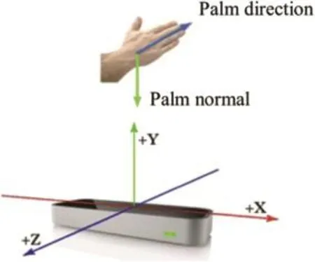
Fig.1.Coordinate definition of LeapMotion.
120°-setup:In this case,when the hand turns over close to 180°,the palm-occlusion occurs.But the side sensor, mounted with an angle of 120°to the bottom sensor,can track the hand.While the hand rotates close to 90°,where the finger-occlusion happens,the side sensor can still track the hand.Moreover,when the hand is within the finger-occlusion or palm-occlusion area of the side sensor,it is simultaneously within the well-tracking area of the bottom sensor. However,when the palm keeps turning over 180°,both of side and bottom sensor will have a worse recognition performance.
In this paper,we aim at performing object manipulation with right hand,which normally will not turn more than 180°. Therefore,one can see that with the120°-setupmethod,the sensors can well cover the blind zone of each other in this case,and gives a continuous tracking when the hand rotate in the common workspace.So we use this setup method to the proposed multi-LeapMotion hand tracking system.

Fig.3.Coordinate transformation in Muti-LeapMotion system.
2.2.Self-registration and coordinate transform
The coordinate system of the two LeapMotion sensors and the tracked hand is shown in Fig.3.TheBO andSO are the coordinate centers of the bottom and side fixed sensors, respectively.And theHO is the coordinate of the tracked hand. TheBTHandSTHare the posture matrices of the hand respectively in coordinates of the bottom and side fixed sensors.To fuse the data from the two sensors,the position and orientation of the hand tracked by the side sensor should be firstly switch to the coordinate of the bottom sensor by the calibration matrix(1).


Fig.2.Three setup methods of the two LeapMotion sensors.a.face-to-face;b.orthogonal-setup;c.120°-setup.
To obtain the calibration matrix,a self-calibration is carried out in the initializing process.The operator flatly put his/her hand with an angle of about-30°to the bottom sensor,while the angle to the side sensor is about-150°.With this orientation and gesture,the hand can be robustly tracked,and the posture matrices of the hand,[BTH1,BTH2,…,BTHi]and[STH1,STH2,…,STHi],are easily obtained.Let the flat hand slowly move,simultaneously record the data from the two sensors and obtain an array of the transformation matrix,[BTS1,BTS2,…,BTSi].The position and eular vectors are extracted from these matrices array.The average value of them are used to reconstruct and get the calibration matrix.
2.3.Workspace analysis
The self-calibration method makes it easier to integrate the entire coordinate system.Whenever one wants to adjust the setup of the two LeapMotion sensors,the only thing they need is to recalibrate the system with the above-mentioned calibration method before using the system.However,limited by the workspace of LeapMotion sensor,we concretely determined the position and orientation of the two sensors.With the desired workspace of the LeapMotionsensor,whichisarectanglarboxwith 235 mm×235 mm×147 mm[25],and the position of the box center is at[0,200,0].The desired workspace of the Muti-LeapMotion hand tracking system is the biggest inscribed cylinder of the two rectangular boxes.Therefore, with the angle of 120°between the two sensors,the position of the side mounted sensor,in the coordinate of the bottom mounted sensor,isBPS[-173,300,0].With these layout,the diameter of the desired workspace is 235 mm with its center at[0,200,0].Fig.4 shows the workspace of the Muti-LeapMotion hand tracking system.
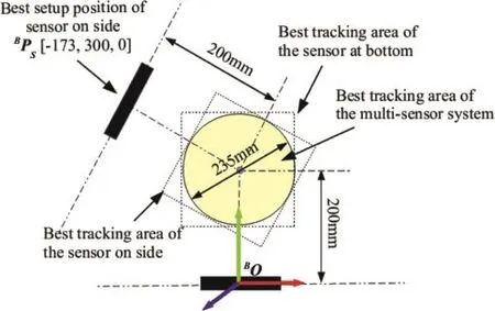
Fig.4.Hand tracking by leap motion sensor.
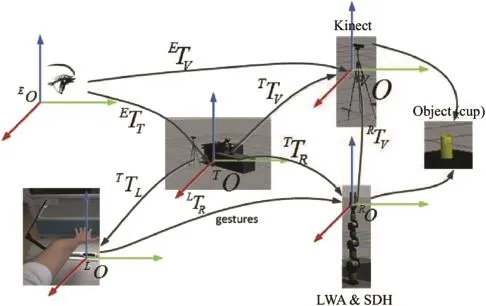
Fig.5.Coordinate transformation of the tele-operative demonstration system.
2.4.Muti-LeapMotion based demostration system
With the aforementioned Muti-LeapMotion hand tracking device,the vision sensor(Kinect)and a manipulator(Light Weight Arm from SchunkTM,LWA),a complete robotic teleoperative demonstration system is constructed.The coordinate system of it is shown in Fig.5.TheEOandLOare the visual and manipulative coordinates of the demonstrator;VOandROare the visual and manipulative coordinates of the LWA;the teaching coordinateTO,which is shown on the screen,is the connection between the demonstrator and the LWA coordinates.With(2),the manipulation coordinates of them are merged so that the position and gesture of the hand in demonstration workspace is mapped into LWA's workspace to perform demonstration or tele-operation.

3.Data fusion in Muti-LeapMotion hand tracking
The position and orientation of the palm and the extension status of each finger can be directly provided by the APIs of LeapMotion sensor.However,this information and status are obtained by the build-in algorithms,which is only available for single LeapMotion sensor.Therefore,it is difficult to fuse the data in these status-level.We use the original position and direction data of each links and joints of the fingers from the two sensors,and fuse them in data-level to gain the correct information of the hand tracking.
3.1.Kinematics model of hand and fingers
In the APIs of LeapMotion sensor,the hand of human is modeled as shown in Fig.6a.3https://commons.wikimedia.org/wiki/File:Scheme human hand bones-en. svgEach finger is consisted by 4 links(metacarpals,proximal phalanges,intermediate phalangesanddistalphalanges)and3joints(metacarpophalangeal joint,proximal interphalangeal joint and distal interphalangeal joint).With the anatomical structure of thumb,it can be considered with a 0-length metacarpal.For each finger,the kinematics model,shown in Fig.6b,includes 4 DoFs(Degree of Freedoms).2 of them are provided by the distal interphalangeal joint and the proximal interphalangeal joint(asR-joint);theother2arefromthemetacarpophalangeal joint(as U-joint),including a lateral rotation.Cause the length of the finger links are constant,the tracking for the gesture of hand can be described by the angle of each DoF of the fingers.
3.2.Data fusion for single finger
For tabletop object manipulation tasks,the most commongestures and actions are grasping,pinching and releasing. In these manipulations,the strength of grasping or pinching depends on the total trend of distal interphalangeal,proximal interphalangeal and metacarpophalangeal angles,rather than just the angle of single joint.The sum of these three angles,jθsi,is taken to be one feature.Moreover,the angle of lateral movement joint,jθli,is another feature.With these two features,the gesture can be finally determined.Where thesandlpresents the total value of the former three angles and the value of the lateral movement angle,respectively;i=[1-5] presents the index from thumb to little finger;andj=[B,S] marks the index of sensors fixed in the bottom or on the side.
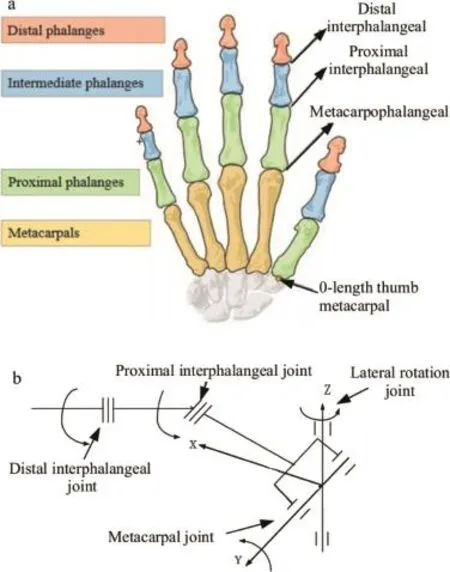
Fig.6.Anatomical structure and kinematics model of human hand.a. Anatomical structure;b.Kinematics model of finger.
To reduce the impact from the noise signal,the recursive average value with data window of 5 frames are used to illustrate thejθsiandjθli.Secondly,for a tele-operative demonstration application,the critical information are the gestures and positions on an array of key points.The hand naturally has a short pause(normally bigger than 0.1 s)on these key points with certain gestures after an action is finished.Therefore,an element action can be de fined with two stable statuses at the beginning and the end,with a dynamic status(rising or declining).The short time average energy of the original data is used to determine whether the status is stable.If the average energy of the current data window is less than 0.0008,we consider the current status is in stable. Otherwise,the recording of the current angle ofjθsiorjθliwill be start.And when the status becomes stable again,the angles will be recorded,and an element action is finished.Fig.7ashows the original data ofBθs2and the element actions recognized by aforementioned method.

Fig.7.Recognition for element actions.a.Bθs2;b.Bθs2andSθs2.
With this method,the time delay of the data from different sensors can be easily calibrated.As shown in Fig.7b,It is not necessary to record the time stamps of each frame of data;but only mark the first start point of the two sensors as the start point of the element action and the last sensor become stable again as the end of the element action.
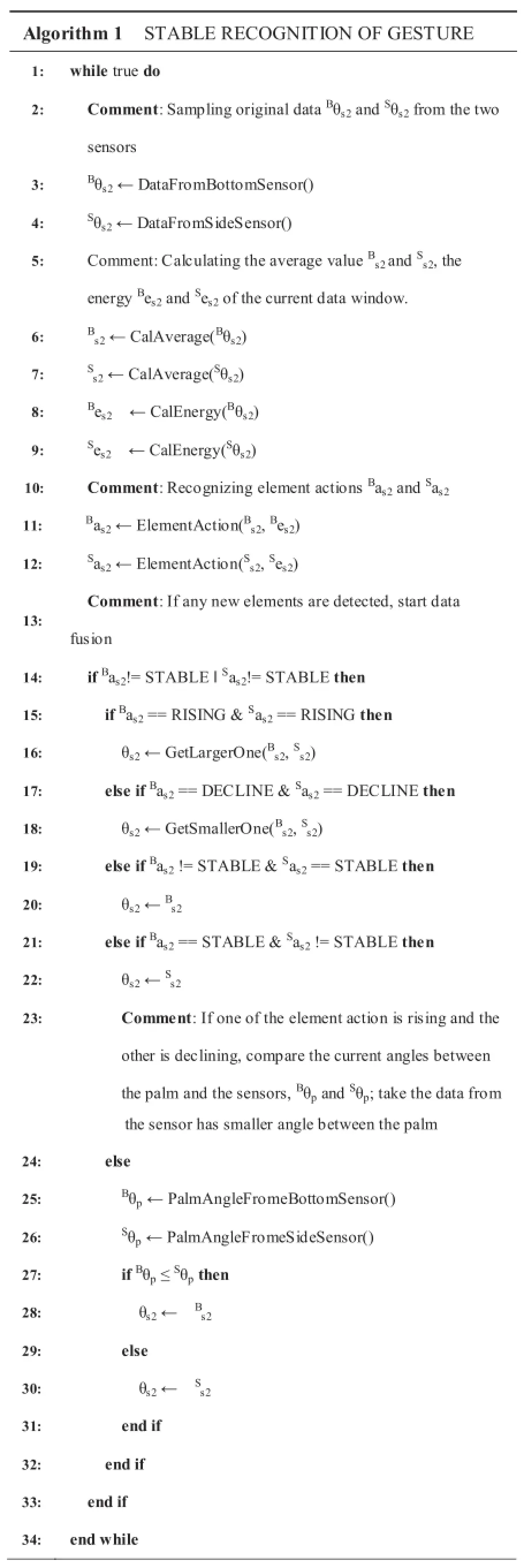
With these element actions,there are several different cases,such as the data from the two sensors are all rising, declining,one stable and one rising,etc.In different cases,we design different principles to fuse the data from different sensors.The detail of the fusion principle is shown in Algorithm 1.Here we take the sum angle of the first three joints of index finger,Sθs2andBθs2,as an example.
3.3.Gesture mapping from human hand to robotic gripper
Cause the different structure of the hand of human and the gripper of a robot,the recognized gestures and actions should be firstly mapped from human hand to a robotic gripper.In [30],we have proposed a method to map the gestures from human hand to robotic gripper,and generate the array of actions for demonstration.Different from the two-finger gripper used in the previous works,in this paper,the gripper we used is a three-finger griper,Schunk™Dextrous Hand(SDH). Therefore,the gesture mapping of typical cup grasping task is shown in Table 1,with the same action generation approach in [30].
4.Experiments
In this section,two groups of experiments are performed: one group of experiments is for testing the proposed Mutli-LeapMotion hand tracking system in gesture recognition;the other group is a scenario experiment in Gazebo4http://www.gazebosim.org.simulation environment to demonstrate the application of the proposed method in tele-operative robotic system.
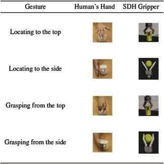
Table 1 Table of gesture mapping.
4.1.Gesture recognition experiments
To test and compare with single LeapMotion hand tracking, the data from different sensors are illustrated with dots in different colors.As shown in Fig.8,the data fromSBis in green,while the data fromSSis in white.It has to be noticed that all these gestures are in some dynamical actions,not only a static gesture.
With one of the most common gesture,grasping from the side(shown in Fig.8a),the gesture is tracked bySBas with thumb extending.This error happens because of the finger occlusion problem.With the correction ofSS,the misrecognition is fixed.For another typical gesture,fisting/ grasping with palm upward shown in Fig.8b,occlusion of SB leads to that it can hardly distinguish full fisting or half grasping.After fusion withSS,the gesture is rightly recognized.In Fig.8c,a very complicated gesture,pinching with thumb and ring finger,is performed.Also with the occlusion problem,SBitself can hardly give an correct recognition.And with data fusion,this gesture is well recognized.
The above mentioned gestures are respectively performed 30 times,and Table 2 shows the experimental result of gesture recognition,which compares the recognition rate between single side mounted sensor,single bottom mounted sensor and the multi-sensor fusion.From the above figures and table,one can see that with the proposed method,not only the gesture recognition rate is improved,but the gestures are also more similar to the actual gestures.
4.2.Tabletop object manipulation experiment
?
In the scenario experiments,we use the proposed Multi-LeapMotion hand tracking device and algorithm to telecontrol a robot to carry out a cup grasping task.As shown in Fig.9a,the remote scene of this experiment is build inGazebo environment,which gives the same interface as physical environment and allow you to avoid the hardware limit for performing experiments.In Fig.9a shows the experiment scene in a Gazebo environment,which includes a robotic manipulator(LWA and SDH),a Kinect sensor providing the view of the experiment scene(based on point cloud data)and the object(acup).The operator carries out tele-control in the local scene with the Multi-LeapMotion hand tracking device mounted on a desk.In R-Viz,position of the robotic manipulator,Kinect sensor and table are fixed or can be tracked by robot itself,so that they are set to be visible. The point cloud provided by the Kinect sensor are also shown in this scene,a-s in Fig.9b.
In the scenario experiment,we tele-operatively control the LWA and SDH to grasp the cup by the side.Fig.10 shows an array of the actions in this experiment.One can see that when the hand is located to the side of the cup,the status of most of the fingers are recognized by SS.While with slowly turning the cup to pour the water away,the status of the fingers can be better detected by SB.The occlusion problem in this sidegrasping and pouring action array is solved,and the total performance of gesture recognition during the dynamic action process is improved.

Fig.8.Gesture recognition experiments.a.Grasping from the side;b.Grasping with palm upward;c.Pinching with thumb and ring finger.

Table 2 Gesture recognition rate.
5.Conclusions and future works
In this paper,a Mult-LeapMotion hand tracking and gesture recognition system is proposed for tele-operative demonstration in robotic systems.The setup structure of the two sensors is analyzed to overcome the finger and palm occlusion problems.
To make the setup procedure more easily and flexible,a self-calibration method is developed for the coordinate transformation between the two sensors.Moreover,the coordinate system of the demonstration system is also developed.
For data fusion and gesture recognition,a simplified kinematics model of finger is built.Two features of each finger,the sum angle of the first three joints and the lateral movement angle,are extracted.The short pause between different gestures are used to detect the three element actions:stable,rising and declining of the feature angles of each finger.The data fusion is only carried out when a new element action happens, so that the delay of the data from different sensors can easily be calibrated.This also makes the data fusion performed in a relatively longer period.The proposed fusion principles make it more stable and higher accuracy in gesture recognition for robotic demonstration.
This proposed Mult-LeapMotion hand tracking and gesture recognition system aims at robotic demonstration for tabletop object manipulation task.In which the real-time performance is not too important,but the key gesture in key positions. Therefore,some nature characteristics of human's hand is taken into the algorithm design,such as the short pausebetween two gestures.Thus,if the similar Mult-LeapMotion device is used for real-time tele-operation in robotic systems,the algorithm should be specifically revised.Moreover, the setup method of the two sensors is primarily for grasping from the side or top of the object.If the palm direct forward or backward,the occlusion problems will happen for both of the bottom or side mounted sensors.To solve these problems, more future works on the optimization of the sensor setup and the revision of the gesture recognition algorithm should be done in our further research.
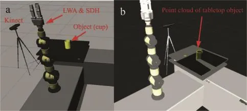
Fig.9.Scene of scenario experiment.a.In Gazebo simulation environment;b.In RViz.

Fig.10.Action array in side-grasping experiment.a.Locating on the side of the cup;b.Grasping;c.Pouring.
[1]Y.Wang,J.Cai,Y.Wang,Y.Hu,R.Xiong,Y.Liu,J.Zhang,L.Qi, Probabilistic graph based spatial assembly relation inference for programming of assembly task by demonstration,in:IEEERSJ International Conference on Intelligent Robots and Systems(IROS 2015),Hamburg, Germany,2015,pp.4402-4407.
[2]K.Ogawara,J.Takamatsu,H.Kimura,K.Ikeuchi,Generation of a task model by integrating multiple observations of human demonstrations,in: Robotics and Automation,2002.Proceedings.ICRA'02.IEEE International Conference,vol.2,2002,pp.1545-1550,http://dx.doi.org/ 10.1109/ROBOT.2002.1014763.
[3]A.Billard,S.Calinon,R.Dillmann,S.Schaal,Robot programming by demonstration,in:B.Siciliano,O.Khatib(Eds.),Handbook of Robotics, Springer,Secaucus,NJ,USA,2008,pp.1371-1394.
[4]R.Hollmann,M.H¨agele,A.Verl,Learning probabilistic models to enhance the efficiency of programming-by demonstration for industrial robots,ROBOTIK 2010(2010)105-111.
[5]M.Hersch,F.Guenter,S.Calinon,A.Billard,Dynamical system modulation for robot learning via kinesthetic demonstrations,IEEE Trans. Robot.24(6)(2008)1463-1467.
[6]J.-P.Hwang,S.H.Lee,I.-H.Suh,Behavior programming by kinesthetic demonstration for a chef robot,in:8th International Conference on Ubiquitous Robots and Ambient Intelligence(URAI),2011,p.875, http://dx.doi.org/10.1109/URAI.2011.6145993,875.
[7]J.van den Berg,S.Miller,D.Duckworth,H.Hu,A.Wan,X.-Y.Fu, K.Goldberg,P.Abbeel,Superhuman performance of surgical tasks by robots using iterative learning from human-guided demonstrations,in: 2010 IEEE International Conference on Robotics&Automation(ICRA), 2010,pp.2074-2081.
[8]L.Rozo,P.Jim′enez,C.Torras,Robot learning from demonstration of force-based tasks with multiple solution trajectories,in:The 15th International Conference on Advanced Robotics,2011,pp.124-129.
[9]L.Rozo,P.Jim′enez,C.Torras,A robot learning from demonstration framework to perform force-based manipulation tasks,Intel.Serv.Robot. 6(2013)33-51.
[10]A.Vakanski,I.Mantegh,A.Irish,F.Janabi-Sharif i,IEEE Trans.Syst. Man Cybern.B Cybern.42(4)(2012)1039-1052.
[11]J.-G.Ge,Programming by demonstration by optical tracking system for dual arm robot,in:2013 44th International Symposium on Robotics (ISR2013),2013,pp.1-7.
[12]A.-L.Vollmer,M.Mhlig,J.J.Steil,K.Pitsch,J.Fritsch,K.J.Rohlfing, B.Wrede,Robots show us how to teach them:feedback from robots shapes tutoring behavior during action learning,PLoS ONE 9(2014), http://dx.doi.org/10.1371/journal.pone.0091349.
[13]C.-S.Fahn,H.Sun,Ind.Electron.IEEE Trans.52(2)(2005)585-594, http://dx.doi.org/10.1109/TIE.2005.844259.
[14]G.Heumer,H.Ben Amor,M.Weber,B.Jung,Grasp recognition with uncalibrated data gloves-a comparison of classification methods,in:2007 IEEE Virtual Reality Conference(VR'07),2007,pp.19-26,http:// dx.doi.org/10.1109/VR.2007.352459.
[15]H.Du,W.Xiong,Z.Wang,L.Chen,Design of a new type of pneumatic force feedback data glove,in:2011 International Conference on Fluid Power and Mechatronics(FPM),2011,pp.292-296.
[16]L.Lukic,J.Santos-Victor,A.Billard,Biol.Cybern.108(2014) 223-248.
[17]Y.Gu,W.Shen,M.Liu,Y.Ou,Fine manipulative action recognition through sensor fusion,in:IEEERSJ International Conference on Intelligent Robots and Systems(IROS 2015),Hamburg,Germany,2015,pp. 886-891.
[18]H.-I.Lin,C.-H.Cheng,W.-K.Chen,Learning a pick-and-place robot task from human demonstration,in:2013 CACS International Automatic Control Conference(CACS),2013,pp.312-317.
[19]A.Erol,G.Bebis,M.Nicolescu,R.D.Boyle,X.Twombly,Comput.Vis. Image Underst.108(1)(2007)52-73.
[20]S.Mitra,T.Acharya,Part C Appl.Rev.IEEE Trans.37(3)(2007) 311-324.
[21]G.Murthy,R.Jadon,Int.J.Inf.Technol.Knowl.Manag.2(2)(2009) 405-410.
[22]T.Starner,J.Weaver,A.Pentland,Pattern Anal.Mach.Intell.IEEE Trans.20(12)(1998)1371-1375.
[23]M.-H.Yang,N.Ahuja,M.Tabb,Pattern Anal.Mach.Intell.IEEE Trans. 24(8)(2002)1061-1074.
[24]Z.Ren,J.Yuan,J.Meng,Z.Zhang,Multimed.IEEE Trans.15(5)(2013) 1110-1120.
[25]Y.Kim,P.C.W.Kim,R.Selle,A.Shademan,A.Krieger,Experimental evaluation of contact-less hand tracking systems for tele-operation of surgical tasks,in:2014 IEEE International Conference on Robotics& Automation(ICRA),2014,pp.3502-3509.
[26]I.Zubrycki,G.Granosik,Using integrated vision systems:three gears and leap motion,to control a 3-finger dexterous gripper,in:Recent Advances in Automation,Robotics and Measuring Techniques,Springer, 2014,pp.553-564.
[27]C.Guerrero-Rincon,A.Uribe-Quevedo,H.Leon-Rodriguez,J.-O.Park, Hand-based tracking animatronics interaction,in:Robotics(ISR),2013 44th International Symposium on,IEEE,2013,pp.1-3.
[28]G.Marin,F.Dominio,P.Zanuttigh,Hand gesture recognition with leap motion and kinect devices,in:Image Processing(ICIP),2014 IEEE International Conference on,IEEE,2014,pp.1565-1569.
[29]G.Marin,F.Dominio,P.Zanuttigh,Hand Gesture Recognition with Jointly Calibrated Leap Motion and Depth Sensor,Multimedia Tools and Applications,2015,pp.1-25.
[30]H.Jin,L.Zhang,S.Rockel,J.Zhang,Y.Hu,J.Zhang,A novel optical tracking based tele-control system for tabletop object manipulation tasks, in:IEEERSJ International Conference on Intelligent Robots and Systems (IROS 2015),Hamburg,Germany,2015,pp.634-642.
Available online 2 June 2016
☆This research is funded by National Natural Science Foundation of China under Project no.61210013,Science and Technology Planning Project of Guangdong Province under no.2014A020215027.
*Corresponding author.Shenzhen Institutes of Advanced Technology, Chinese Academy of Sciences,Xueyuan Avenue 1068,Shenzhen,518055,
China.Tel.:+86 755 86392182.
E-mail address:ying.hu@siat.ac.cn(Y.Hu).
Peer review under responsibility of Chongqing University of Technology.
http://dx.doi.org/10.1016/j.trit.2016.03.010
2468-2322/Copyright©2016,Chongqing University of Technology.Production and hosting by Elsevier B.V.This is an open access article under the CC BY-NCND license(http://creativecommons.org/licenses/by-nc-nd/4.0/).
Copyright©2016,Chongqing University of Technology.Production and hosting by Elsevier B.V.This is an open access article under the CC BY-NC-ND license(http://creativecommons.org/licenses/by-nc-nd/4.0/).
杂志排行
CAAI Transactions on Intelligence Technology的其它文章
- An efficient shortest path approach for social networks based on community structure☆
- A framework for multi-session RGBD SLAM in low dynamic workspace environment
- RPK-table based efficient algorithm for join-aggregate query on MapReduce
- Frame interpolation with pixel-level motion vector field and mesh based hole filling
- Exploiting structural similarity of log files in fault diagnosis for Web service composition
- Background modeling methods in video analysis:A review and comparative evaluation
