Hybrid-polarity Architecture Based Polarimetric SAR: Principles and Applications (in Chinese and in English)
2016-02-13HongWen
Hong Wen
(National Key Laboratory of Microwave Imaging Technology,Beijing100190,China)
(Institute of Electronics,Chinese Academy of Sciences,Beijing100190,China)
(University of Chinese Academy of Sciences,Beijing100049,China)
Hybrid-polarity Architecture Based Polarimetric SAR: Principles and Applications (in Chinese and in English)
Hong Wen*
(National Key Laboratory of Microwave Imaging Technology,Beijing100190,China)
(Institute of Electronics,Chinese Academy of Sciences,Beijing100190,China)
(University of Chinese Academy of Sciences,Beijing100049,China)
The application performance of Synthetic Aperture Radar (SAR) instruments is generally limited in their capability to acquire radar images with both high-resolution and wide swath coverage. The available swath width of Polarimetric SAR (PolSAR) systems is even more restricted. Recently, a new PolSAR architecture called the Hybrid-Polarity (HP) architecture has attracted worldwide attentions. Compared with conventional linearly-polarized PolSARs, HP architecture based PolSARs have significant advantages such as wider swath coverage and lower hardware requirement. In this paper, the principles of the HP architecture, including system designs, system models and calibration methods are first reviewed. Two implementation difficulties of the HP architecture, concerning calibration issue and transmit configuration are illustrated. In order to overcome these problems, an improved version of the HP architecture is proposed. A prototype system based on this improved HP architecture developed for experimental validation is also introduced. In the latter part of this paper, applications suitable for the HP architecture based PolSARs are reviewed. Since the quadrature-polarimetric (quad-pol) data provided by an HP architecture based PolSAR system may be directly transformed into conventional linearly-polarized quad-pol data, this part of review is mainly focused on the corresponding dual-pol applications,i.e.Compact Polarimetry (CP) applications.
Synthetic Aperture Radar (SAR); Polarimetric SAR (PolSAR); Hybrid-polarity architecture; Compact Polarimetry (CP); Calibration; Classification; Compact PolSAR interferometry
1 Introduction
Synthetic Aperture Radar (SAR) is an active imaging radar, which produces high-resolution microwave images of the earth’s surface via signal processing technologies. It has all-day and allweather imaging capability. Polarimetric SAR (PolSAR) offers additional polarimetric information of the observed scene and has already been successfully applied in a multitude of practical applications[1,2]. The limitation of current spaceborne SAR systems is mainly the acquisition of radar images with both high-resolution and wideswath coverage. As for fully, or quadrature polarimetric polarimetric (quad-pol) SAR systems, which could obtain the complete backscattering characterization of scatterers, the available swath width is at least halved compared with conventional SAR systems due to the doubled Pulse Repetition Frequency (PRF) for interleaved transmission of two orthogonal polarizations.
Conventional quad-pol SAR systems operate with Horizontal (H) and Vertical (V) linear polarizations in both transmission and reception. This configuration will give rise to severe range ambiguities in the cross-polarized (HV or VH) measurement channels, which will further limit the swath coverage particularly at larger incidence[3,4]. Meanwhile, since the like-polarized (HH or VV) returns from natural terrain are generally 6~10 dB higher than the cross-polarized (HV or VH)returns, complex reception strategies are applied in practical radar systems to keep both measured returns within the valid dynamic range of the Analog to Digital Converter (ADC) module[5,6]. On account of these drawbacks, a new PolSAR architecture called the Hybrid-Polarity (HP) architecture, has been proposed in Refs. [4,7,8] in recent years. By transmitting interleaved Right-Handed Circular (RHC) and Left-Handed Circular (LHC) polarized waves and receiving on orthogonal linear polarizations, the range ambiguity performance of the HP architecture based PolSAR system is improved for having no like- or cross-polarized relationship between the transmitting and receiving polarizations[4]. Meanwhile, the mean signal level in either receiving path is also balanced, which implies that no complex reception strategies are more needed. Thereby, PolSAR systems based on the HP architecture will have wider swath coverage and lower hardware requirement than conventional linearly-polarized PolSAR systems[4].
The HP architecture can also support the Circular Transmit Linear Receive (CTLR) mode[7]of Compact Polarimetry (CP), a collection of special dual-polarimetric (dual-pol) modes, which requires the transmission of polarizations with equivalent H and V components, such as RHC and LHC polarizations and the ±45° slant linear polarizations, and retains the relative phase of the received polarizations[9-12]. CP has attracted wide attentions in the past ten years for having the potential to produce comparable results in many applications as those derived from quad-pol SARs[12-61]while maintaining the advantages of dual-pol SARs such as doubled swath width, low power consumption and low system complexity[7,9].
These advantages make the HP architecture a potential choice for future PolSAR missions. To date, several launched PolSAR missions have adopted the HP architecture: the two mini-Radio-Frequency (mini-RF) radars onboard the Indian Chandrayaan-2-1 moon mission and the American Lunar Reconnaissance Orbiter (LRO)[62], the C-band SAR onboard the Indian remote sensing satellite RISAT-1[63], the L-band SAR onboard the Japanese remote sensing satellite ALOS-2 (experimental mode)[64]. Future SAR missions including the Canadian C-band RADARSAT Constellation Mission (RCM)[12,65,66], the American L-band Interferometry SAR (InSAR) system of the Deformation, Ecosystem Structure, and Dynamics of Ice (DESDynI) mission[67,68]; and the second moon mission of Indian Space Research Organization (ISRO) Chandrayaan-2[69]have also confirmed to adopt the HP architecture.
In this paper, we will first review the basic principles of the HP architecture including system designs, system models, and calibration methods. Two implementation difficulties of the HP architecture will be discussed. The major one is that when operating under the dual-pol mode, the distortions in transmit cannot be calibrated, even if their actual values can be precisely measured with specific calibration methods. The other one is that the transmission in the HP architecture are usually configured as circular polarization. Under this configuration, the dual-pol mode corresponds the CTLR mode. However, beside the CTLR mode, other CP modes with different transmit polarization such as the π/4 mode, which radiates 45° linearly-polarized waves with respect to either H and V orientations, may also produce favorable results in certain applications and deserves consideration. To deal with these two problems, an improved version of the HP architecture will be proposed in this paper. The prototype system developed for experimental validation will also be introduced.
In the next part of this paper, applications suitable for the HP architecture based PolSAR will be illustrated. Since the quad-pol data provided by HP architecture based SAR systems can be directly transformed into conventional linearly-polarized scattering matrix, this part of review will mainly focus on the corresponding dualpol applications,i.e. CP applications. Four CP information retrieval methodologies, including the covariance matrix expansion method, the Stokes vector based method, the eigenvalue decomposition method, and the scattering model based method will be first introduced. Suitable applications stemmed from these methodologies will be reviewed next. Considering the length of the pa-per, only investigations on unsupervised classification of land and terrains using CP data and Compact PolSAR interferometry for tree height inversion will be reviewed in detail.
The organization of this paper is given as follows. In Section 2, the system designs and system models of the HP architecture based dual-pol and quad-pol SAR systems are reviewed, respectively. In Section 3, the self-checking property[7]of the HP architecture and calibration techniques are illustrated. Assessment of the transmit distortions, which cannot be calibrated using external calibration methods, are also discussed. In Section 4, an improved version of the HP architecture is proposed. In Section 5, several data processing algorithms including the transformation of HP quad-pol data to linear quad-pol data, and the simulation of CP data with quad-pol data are introduced. Four major CP information retrieval methodologies are also illustrated in this section. In Section 6, investigations on CP applications are reviewed. Conclusions are finally made in Section 7.
2 Hybrid-polarity Architecture
2.1 Hybrid dual-pol architecture
The HP architecture was first proposed in Ref. [7] to support the CTLR mode of CP, which requires the transmission of single circular polarization (either RHC or LHC) and simultaneously receiving on two orthogonal linear polarizations. Since CP is actually a collection of special dualpol modes, this HP architecture is referred as the Hybrid Dual-Pol (HP2) architecture in this paper. The block schematic of the HP2 architecture is shown in Fig. 1(a). In order to produce circular polarization for transmission, the signal flow generated by the waveform generator is split in two with a power splitter and one of the sub-signal flow is phase shifted 90° afterwards. This part of design is highlighted with a dashed frame in Fig. 1(a). The two sub-signal flows are used to feed the H- and V-elements of a dual-linearly-polarized antenna. The outlined part of the HP2 architecture could be simplified as Fig. 1(b), withSiandSodenoting the input and output ports, respectively, andAtandArdenoting different ports connected to the feeds of the transmitting and receiving antennas, respectively. If the dual-linearlypolarized antenna is used for both transmission and reception, thenAt1=Ar1andAt2=Ar2.
As we can see, very few RF hardware is required in the HP2 architecture, which implies fewer losses and fewer sources of potential distortion sources in the radar system. Besides, since neither receive channel is disadvantaged by being cross-polarized, the mean signal level in both channels should be similar. This means also that there will be less chance of having a stronger polarization affect a weaker polarization,i.e. having a strong crosstalk within the radar system[4].
The system model of the HP2 architecture based spaceborne PolSAR system is[70]:


Fig. 1 Block schematic of the HP2 architecture (Raney 2007, Ref. [7])

whereMis the measured scattering matrix,Sis the scattering matrix,RFrepresents the one-way Faraday Rotation (FR) matrix withΩbeing the FR rotation angle,Ris the receive distortion matrix, andNis the additive noise term present in each measurement. The subscripts inMstands for RHC polarization transmission and H and V polarization reception.Rincludes the crosstalk term δ1and δ2, and the channel imbalance termf1within reception.kRHCandkLHCare the Jones vectors of RHC and LHC polarization, respectively, andδis the general crosstalk when RHC polarization is transmitted. The real factorArepresents the overall gain term, which is the function of range,r, and elevation angle, φ. The complex factor ejφrepresents the round-trip phase delay and system-dependent phase effects on the signal.
The electric fieldEiincident on the surface could be further derived as:

We can see that if the transmitted circular polarization is perfect,i.e.δ=0, then FR can be omitted in the following processing. Even if the transmitted polarization is imperfect, the FR effect upon an HP2 architecture based PolSAR system should be still smaller than those affected on traditional linearly-polarized SAR systems.
Although the distortions in transmission can be simply represented with one single term, as in Eq. (1) and Eq. (2), such distortions can also be expressed with conventional transmit distortion matrixT[71]:

where δ3, δ4, andf2are the crosstalk and channel imbalance terms in transmission, respectively. These distortion terms are connected with the general crosstalk δ through Eq. (5)[72]:

Either expressions of the transmit distortions is applicable. But as we can see in Eq. (1), even if the distortion terms on transmit are explicitly known, the real scattering matrix of the target can still not be obtained through multiplying a corresponding inverse matrix. Therefore, it will be more concise by using the general crosstalk term. But the explicit formulation of the transmit distortions allows us to assess the influences of different distortion sources in detail, respectively. This part of work will be reviewed in Subsection 3.2.
2.2 Hybrid quad-pol architecture
As an alternative to conventional linearly-polarized quad-pol SAR systems, it was suggested in Ref. [7] to use the HP architecture to configure a quad-pol SAR system. The transmitted polarizations would be RHC and LHC, interleaved, and the receive polarizations would be coherent H and V polarizations. This idea was further elaborated in Ref. [4] and Ref. [8].
The block schematic of the Hybrid Quad-Pol (HP4)[8]architecture is shown in Fig. 2(a). The transmit module is similar to the introduced HP2 architecture, with a small modification in the phase shifter. The phase of the signal flow will be shifted between +90° and -90° for RHC and LHC polarization transmission, respectively. This part of design is also outlined in Fig. 2(a) and simplified in Fig. 2(b). If the phase shifter is fixed at either +90° or -90°, the resulting system design is the HP2 architecture. Therefore, the CTLR mode can be regarded as the corresponding dual-pol mode of the HP4 architecture based PolSAR system. In the following text, we will use the phrase“HP architecture” to indicate an HP4 architecture, which can also operate under dual-pol mode.

Fig. 2 Block schematic of the HP4 architecture (Raney 2008, Ref. [8])
The advantages of the HP2 architecture denoted in previous subsection is also inherited by the HP4 architecture. First, there are also no likeor cross-polarized relationship between the transmitted and received polarization. According to the deductions made in Ref. [4], this feature will lead to a better range ambiguity performance, which implies that an HP4 architecture based quad-pol SAR system can have a wider swath coverage, particularly at higher incident angles than conventional linear quad-pol SAR systems.
Moreover, since the mean signal level in both receive channels are similar, conventional complex reception strategies to adjust the receiver gain for different returns[5,6]are also no longer needed. Therefore, comparing with conventional linearly-polarized PolSAR systems, the system design of the HP4 architecture based PolSAR system is much simpler, which in turn implies a less costly radar and more robust calibration and measurement reliability.
Since there is no need to toggle the gain of receivers between either radar returns, the system model of the HP4 architecture based spaceborne PolSAR system is similar to the standard polarimetric system model concerning the FR effect[73]:

whereMHP4is the 2×2 measured matrix andSHP4is a 2×2 matrix, which composes the elements of a true scattering matrixSby:

The measurement obtained with the HP4 architecture based PolSAR could also be first transformed into linear basis, and then apply the standard polarimetric system model developed for conventional linearly-polarized quad-pol SAR systems for further calibration and data processing algorithms.
3 Calibration and Assessment of Distortions
Since the data derived from HP4 architecture based PolSAR system could be transformed into conventional linear basis, standard algorithms developed for polarimetric calibration could be directly applied on the HP4 architecture based PolSAR systems. The calibration issue left for the HP architecture is the calibration of data obtained through HP2 architecture based PolSAR systems,i.e. the calibration of CP data.
3.1 Calibration of CP data
3.1.1 Self-checking calibration methodSince the mean signal level in both receive path of the HP architecture based PolSAR system is expected to be balanced, the first- and second-order statistics of the return signals should be identical when the H and V backscatter coefficients are equal. In practice, this criterion is achieved when the radar views at an incident angle that is normal to the mean slope of the illuminated terrain. The discrepancies, which do not meet this criterion, can be measured and compensated[7,74].
This unique calibration strategy of the HP architecture has been adopted by the lunar mini-RF programs[62,75]. Since there are no Amazon rain forests, nor specially placed radar reflectors available on the Moon, standard calibration techniques used by Earth orbiters were not applicable. During the on-orbit calibration experiment, the spacecraft was rolled to align the mini-RF radarantenna in a nadir-pointing orientation towards the Moon to cooperate the calibration experiment. The V-H gain balance and V-H phase balance were counted to be -2.55 dB±0.25 dB and -138°±2.7°, respectively. These results compare well with the predictions made through an end-toend system measurement, which were -2.14 dB±0.25 dB and -135.9°±1.5°, correspondingly. The small difference between these two strategies was mainly due to the actual imperfect transmitted circular polarization, which was measured having an Axial Ratio (AR) of 2.46 dB±0.15 dB.
3.1.2 Quad-pol based calibration methodAn HP architecture based PolSAR system can operate under both quad-pol mode and dual-pol mode. Therefore, if such system is stable during the data-taking stage, as is the case for spaceborne SARs, the discrepancies within the system could be directly obtained by operating quad-pol mode at the beginning and/or the end of the data-taking stage[70].
3.1.3 Calibration of faraday rotationAs for spaceborne PolSAR systems operating with low frequency microwaves, the FR effect must also be taken into consideration. Beside the usage of Total Electron Content (TEC) maps[76], FR angles can also be estimated through backscatters from bare surfaces, where the HH-VV phase difference is close to zero[18]. The identification of bare surfaces was made by the conformity coefficientμ, which is FR independent:

As for bare surface scattering,μis positive and conforms one. Meanwhile, theμvalue for doublebounce scattering is negative and conforms to -1, and the intermediate value (near zero) denotes volume scattering. The threshold between volume and surface is estimated 0.35 and the threshold between volume and double-bounce is estimated -0.2. Utilizing the identified bare surfaces, FR angles can be derived through the following equation:

3.1.4 Calibrator based calibration methodIn Ref.[77], Truong-Loïet al. first proposed a calibrator based calibration method for the CTLR mode. Since the transmit distortions could not be corrected, the transmission of the radar system is considered perfect. Three calibrators, including two dihedrals at 0° and 45° and a trihedral at 0° are utilized to measure and correct the channel imbalance and cross-talk in reception, FR angle and system gain.
In Ref. [78], Chen and Quegan also investigated several calibrator-based calibration strategies for spaceborne low-frequency SAR systems operating with CTLR mode. In their investigation, six different calibration schemes, containing different mixtures of passive and active radar calibrators, were proposed and carefully investigated. First, it was established that calibration strategies involving four calibrators will yield a more accurate estimation of the radar system parameters than those using just three calibrators. However, the augment in cost and complexity in deployment deserves careful consideration. Second, among the three passive calibrators, gridded trihedral is the most preferred against the dihedral and trihedral, because of its much lower Average Polarimetric Noise (APN) and insensitivity to pointing accuracy. The mostly recommended calibration scheme concludes two gridded trihedrals that select for the HH and VV channels, and two active calibrators that select for the HV and VH channels.
In Ref. [79], Chenat al.proposed a general calibration algorithm for all dual-pol SAR systems using only one trihedral and two dihedrals, 0° and 45° in rotation angle. The FR effect is not considered in this method. This method is applicable for all dual-pol modes including the conventional linear dual mode, the CTLR mode, and the π/4 mode of CP. The effectiveness of this algorithm has been verified with a ground-based SAR system with π/4 mode and CTLR mode transmit/receive configurations[34].
3.2 Assessment of the transmit distortions
In previous section, we have discussed one major implementation difficulty of the HP architecture: the transmit distortions in its corresponding dual-pol mode cannot be corrected by simply multiplying a corresponding inverse matrix. Therefore, the influence of such distortions requires careful assessment. In Ref. [71], Guoet al.adopted the Maximum Normalized Error (MNE)[80]for quantitative evaluation. In the case with the HP2 architecture based PolSAR system, MNE is defined as:

This evaluation campaign can be used to assess the influence of transmit distortions caused by multiple sources, including FR, channel imbalance and crosstalk in transmission, and incident angle. However, in order to assess the influence caused by each distortion source alone, the corresponding MNE changes of each distortion source is simulated, respectively.
3.2.2 Channel imbalanceAssuming that the only existent distortion in transmission is channel imbalance,i.e. δ3=δ4=0. Fig. 3 shows the contour lines of MNE due to the interaction of the differential gain factor and the relative phase difference between the H and V channels. To maintain the MNE less than -20 dB, the approximated elliptical boundary could be determined at ±1.2 dB gain and ±8° phase offset.

Fig. 3 MNE evaluation due to channel imbalance
3.2.3 CrosstalkFor the sake of simplicity, the crosstalk is here assumed |δ3|=|δ4|, and no other distortions exist. Experimental results show that the phase offsets of the crosstalk have no effect on MNE. Therefore, only crosstalk gain is investigated. The result is shown in Fig. 4. As we can see, MNE increases proportionally with crosstalk level on the decibel scale. In order to keep MNE lower than -20 dB, the crosstalk at transmission should be maintained less than -20 dB.

Fig. 4 MNE evaluation due to crosstalk gain
3.2.4 Incident angleIt is admitted that the noncircularity of the transmitted wave also increaseswith the change of incidence angle[65]. In Ref. [65], Touzi and Charbonneau estimated that the AR of the transmitted polarization with RCM may vary between 1.4 dB (within 50 km at 0° beam scan angle) and 3.0 dB for the most raising beams of the 350 km ScanSAR swath. Such AR variations correspond to an elliptical polarization whose ellipticity varies between 35° and 41°. To evaluate such influence, the transmit Jones vector is set as[81]:

In this case, only ellipticity is taken into consideration and the orientation angle is set asThe MNE evaluation is shown in Fig. 5. We can see that the value of MNE increases with the bias from the ideal value (45°). To maintain an accuracy better than -20 dB, the bias of the ellipse aperture should be within [-5°, 5°]. While the ellipse aperture drops to 35°, which is the worst case estimated by Touzi and Charbonneau, MNE is approximately -15 dB.

Fig. 5 MNE evaluation due to the change in ellipticity
4 Improved Hybrid-polarity Architecture
4.1 System design
As introduced in previous sections, the HP architecture has one major implementation difficulty within the calibration issue: the transmit distortions can not be calibrated when working under the dual-pol mode, even if the values of transmit distortions can be precisely obtained through various external calibration methods. Therefore, those transmit distortions are always neglected in most HP system related papers. But as is shown in Subsection 3.2, transmit distortions will surely have certain influence on the HP architecture based PolSAR system.
In Subsection 3.2, the transmit distortions are evaluated by MNE, which is a generic metric defined to measure the polarization purity of a PolSAR system. On the other hand, the transmit distortions can also be quantified by their outcomes, which is the distortion of transmitted polarizations. Under this point of view, AR is used to quantify transmit distortions. As for a perfect circularly polarized wave AR=0 dB, and AR=+∞ is for a linearly-polarized wave. It is reported that the transmitted polarization in the two Lunar Mini-RF radars have an AR on the order of 2.5 dB[62]. Besides, it is expected that AR may vary between 1.4 dB and 3 dB in the worst case of the upcoming RCM radar system[65], and the radar system of the second moon mission of ISRO is designed to have an AR of less than 2 dB[69]. According to our research, AR and MNE values are not one to one related. But AR should be less than 1.8 dB to fulfill the aforementionedcriterion.
In order to overcome this flaw, internal calibration techniques should be built in the HP architecture based PolSAR systems. But conventional internal calibration loops may greatly increase the RF hardware required in the radar system, which implies an augment in cost and potential distortion sources. Alternatively, we have just modified the transmit module of the HP architecture. The block schematic of the resulting improved HP architecture is shown in Fig. 6(a). The modified transmit module is also outlined and simplified in Fig. 6(b). Comparing with the system designs shown in Fig. 1(b) and Fig. 2(b), the original ±90° phase shifter is replaced by two high-accuracy variable attenuator and 360° -covering phase shifter, denoted by “A” and “P”, respectively.
鄱阳湖区圩堤管理单位与堤防管理人员在以往的堤防管理工作中,特别是在在历次的抗洪抢险工作中,在各级水行政主管部门的领导下,发挥了极大的作用,为防洪减灾、为当地的工农业生产和购买经济建设作出了很大贡献。鄱阳湖生态经济区重要圩堤管理单位基本分为县、乡管理模式。如廿四联圩长90km,由新建县廿四联圩管理局管理,属事业单位,管理员6人,年均投入维护资金10万元。这种管理性质的差异体现在管理工作中的结果是职能不清,责任不明,有事无人管,经费无保证。

Fig. 6 Block schematic of the improved HP architecture
With these improvements, a pre-distortion technique can be used to correct the transmit distortions. First, the attenuator and phase shifter are tuned so that the two transmit path have balanced power level and wanted phase difference (for example +90° or -90° for circular polarizations). Next, the transmit distortions are measured with calibration methods introduced in previous section. Then, we can further tune the attenuator and phase shift to compensate those distortions. Thereby, the transmit distortions can be mitigated to an acceptable level.
With the two high-accuracy tunable attenuator and phase shifter, the PolSAR system based on the improved HP architecture can also generate arbitrary transmit polarizations. Original HP architecture based PolSAR systems usually operate with circularly-polarized transmissions with the consideration of mitigated FR effect and having no rotational selectivity upon the observation. But other transmit configurations also deserve further researches and applications. For example, Ref. [29] founded that with π/4 mode data, better decomposition results can be derived than those derived from CTLR mode data utilizing model-based decomposition algorithms[29]. Similar algorithms can also be applied to π/4 mode compact PolSAR interferometry (PolInSAR) data and produce promising target decomposition results[31].
Similar to the original HP architecture, the improved HP architecture can also support quadpol mode. By switching the attenuator and the phase shifter, the improved HP architecture can produce interleaved orthogonal polarization pairs. Although arbitrary transmit polarization pairs can be generated, but in order to retain the advantage of having a wider swath coverage, the adopted transmit polarization pairs should differ from the receive polarization basis,i.e. H and V polarizations.
4.2 System model
The system model introduced in Subsection
2.1 and Subsection 2.2 also suits for the improved HP architecture based PolSAR system. When operating under dual-pol mode, the Jones vector of the transmitted polarization with general transmit distortion termδin Eq. (1) and Eq. (2) should be adjusted accordingly. For example, if traditional H and V transmission, or the aforementioned slant linear polarization are utilized in transmission, those term should be adjusted as[79]:

As for the quad-pol mode, the 2×2 matrixSHPAin Eq. (7) should be adjusted according to the utilized transmit and receive polarization pairs.
4.3 Prototype system
As is shown in Fig. 7, our research team has already built a prototype system consisting the transmit and receive modules of the proposed improved HP architecture. A Vector Network Analyzer (VNA) is utilized to measure the magnitude and phase characteristics of the prototype system. Besides, we have also developed a program to control the attenuators, phase shifter and switches within the prototype system and communicate VNA through network. The pre-distortion related functions are also built in the program. It is estimated that the AR of the circular polarized wave transmitted by an ideal dual-linearly polarized antenna can be maintained within 1 dB with the pre-distortion technique.

Fig. 7 Prototype system of the improved HP architecture measured by a VNA
Another issue to be discussed is the usage of different antennas. In original HP architecture, it is suggested to utilize one dual-linearly polarized antenna for both transmit and receive. But we can also use two orthogonal single polarized antennas to replace one dual-linearly-polarized antenna. If different antennas are used for transmitting and receiving, then up to four single polarized antennas are required. In this research program, we have adopted this antenna configuration including four single polarized antennas. This configuration has the advantage of lower cost and better isolation, but suffers from parallax problem due to the boresight separation between two different antennas. Whether this trade is favorable still requires further verification.
Utilizing this prototype system, we will first validate the expected pre-distortion feature. Next, we will implement further experiments on different CP modes and assess actual influence of the transmit distortions on different radar observations. As for the analysis of data obtained from the improved HP architecture based PolSAR system, the unified data analysis framework for general compact and quad-pol SARs developed by Sabry and Vachon[82]can be applied.
5 Data Processing Methodologies
According to basic radar polarimetry theories[81], any quad-pol data can be directly transformed into other polarimetric data with different transmit/receive configuration, including dual-pol mode data. Therefore, quad-pol data derived from the HP architecture based PolSAR system can be directly transformed into conventional linear quad-pol data. Thereby, analyzing tools developed for conventional PolSAR can be similarly applied to HP architecture based quad-pol SARs.
On the other hand, the corresponding dualpol modes,i.e. CP modes, of the HP architecture based PolSAR was newly introduced in the past ten years. Corresponding data processing methodologies and applicable applications still deserves to be reviewed. In the following two sections, data processing methodologies and the applications based on both CTLR mode and π/4 data are introduced, since those data could be derived from the proposed improved HP architecture.
5.1 CP data simulation
To date, only RISAT-1 and ALOS-2 are capable of providing CP data. ALOS-2 has acquired CP data with experimental mode, and those data are still not made public for the research community. Therefore, most CP researches are still based on simulated CP data, which is the dualpol data directly transformed from corresponding quad-pol data. As is illustrated above, any quadpol data can be used to transform other polarimetric data, including dual-pol data. An example of transmitting linear quad-pol data to CTLR mode data is shown in the Appendix of Ref. [7]. This formulation utilized the covariance matrixC3of conventional linear quad-pol data. Similarly, one can use the coherency matrixT3of conventional linear quad-pol data to simulate CP data[83]. In Ref. [11], the scattering vectors and covariance matrices of all three CP modes composed by the elements of the 2×2 Sinclair matrix are also shown. This transformation process could also be carried out in the newest PolSAR Pro 5.0 software[84].
It is important to note that though the transformed CP data is called as “simulated CP data”, but since the quad-pol data used for transformation is real, the generated CP data is real. Moreover, this transformation also makes the comparison between CP and quad-pol repeatable, since same data is used in either cases.
5.2 Fundamental data products
The fundamental data products of the CPdata include the 2×2 covariance matrixC2and the Stokes vector (SV)

where the 〈·〉 function represents spatial averaging,kCPis the scattering vector of different CP modes, and *T stands for conjugate transpose. According to the investigations using the Monte Carlo simulation[38,40,71], the spatial averaging performed in Eq. (19) must be at least 49 looks (a 7×7 boxcar filter, or other filters with equivalent number of looks) to obtain reliable polarimetric child parameter estimation. These data products could be further processed by the following methodologies.
5.3 CP information retrieval methodologies
5.3.1 Covariance matrix expansion methodAccording to Ref. [11], the covariance matrixC2of the three main CP modes can all be expressed as a sum of three terms: one only contains elements which have dependency withSHHandSVV, one contains |SHH|2elements, and another term is consist of only co-polarization correlations. Based on the reciprocity assumption,i.e.SVH=SHV, and the reflection symmetry assumption,i.e.unknowns inC2can be simplified into only five scalars,i.e. |SHH|2, |SHV|2, |SVV|2, and the real and imaginary part ofIf one further constraint of these five scalars could be found, thenC2can be further expanded into a conventional 3×3 covariance matrixC3. The expanded covariance matrix is also called as pseudo quad-pol data. The constraint assumed in Ref. [9] is:

This constraint is further developed by Nordet al.[11]as:

where

Utilizing these constraints, the value of |SHV|2can be derived though an iterative solving process. Thus, other unknowns of the pseudo quadpol data could be calculated. There are also some other reconstruction algorithms, which are either based on the scattering decomposition models[48,85]or the eigenvalues of theC2, or Degree of Polarization (DoP)[86,87]. Detailed assessment and comparisons of these approaches could be found in Ref. [87].
This kind of retrieval method has the advantage that, once the pseudo quad-pol data is obtained, all analysis tools developed for quad-pol SARs could be directly applied. However, the objective in many applications of PolSARs is to ascertain the scattering properties of the scene, rather than to presume them at the outset, and to realize image classification over an unconstrained variety of scene characteristics. Therefore, the application of this methodology is in fact restricted.
5.3.2 Stokes vector based methodPolarimetric information contained in CP data could also directly extracted from SV, from which various child parameters containing different polarimetric features could be generated[7,62,88]:
The aforementioned DoP:

The degree of linear polarizationmL:

The linear polarization ratio μL:

The degree of circular polarizationmC:

The Circular Polarization Ratio (CPR)

The relative phase between the two linearE-vectors of the backscattered field:

Besides these six child parameters, other two very important parameters derived from SV are: the target parameter αs, derived from compact Random Volume over Ground (RVoG) scattering model[83], and the Poincaré ellipticity parameter
In Ref. [83], the compact RVoG scattering model is formed as:

where the upper and lower signs are for LHC and RHC transmission, respectively. The corresponding target parameters are:

As we can see, in the compact RVoG scattering model, SV is decomposed into two separated terms, one denoting random volume, and the other denoting polarized surface or ground component.
According to the well-known Born and Wolf wave decomposition[81], SV could also be decomposed into a completely polarized and a completely depolarized wave component, in which the polarized term could be further written as a function of the polarization ellipse parameters,i.e. the orientation angleψand the ellipticity angleχ:

Comparing the decomposition models in Eq. (30) and Eq. (33), we can conclude that φ=ψ, and αsis surely related to the ellipticityχ through:

These two parameters and the aforementioned relative phaseδare usually utilized as an indicator of surface and double-bounce scatterers. But as the dependence of the orientation angle is undesirable,αsandχare usually more prefered in decomposition and classification algorithms.
5.3.3 Eigenvalue decomposition based methodSimilar to the famousH/alpha decomposition algorithm,C2could also be directly decomposed with the eigenvalue decomposition[40,83,91]:

where λiandiare the eigenvalues and the unitary eigenvectors ofrespectively. The wave entropyHwand the scattering angle α can be further obtained as:

The boundary curves of the derivedHw/α plane can be derived through settingas:

Optimal boundaries between different Polarimetric Scattering Mechanisms (PSMs) were fully investigated in Ref. [40] for various sensor data, including various spaceborne and airborne platforms.
It is established that this method is only applicable to CP data under the dual circular polarization (DCP, or CC) mode, which transmits circular polarization, and receives in orthogonal circular polarizations[10]. But since the scattering vectors of the CTLR mode and CC mode are lin-early related through the following equation[91]:

wherekCLandkCCare the scattering vectors of the CL and CC mode, respectively. Thereby, CTLR mode data can be directly transformed to CC mode data, and thus apply this method.
5.3.4 Scattering model based methodIn the famous Freeman-Durden decomposition, quad-pol SAR data can be decomposed into three canonical scattering components utilizing three physically based scattering models[92]:

wherefv,fd, andfsrepresents the contribution of volume, double-bounce, and surface components, respectively, |α|¸1 represents the conjugative value between HH and VV terms of the double-bounce component, and |β|<1 is the conjugative value between HH and VV terms of the surface component.
Similarly, the 2×2 covariance matrixcould also be formed as the sum of these three scattering components[93,94]:

For both modes, there are up to 5 unknowns (or 10 real unknowns) innamely:and β, and only 4 knowns,i.e. the four elements ofC2. Therefore, similar to the pseudo quad-pol reconstruction method, at least one further constraint of the unknowns must be set to solve the system of equations. In Ref. [93] and Ref. [94], Liuet al.and Guoet al.both followed the assumption made in Ref. [92],i.e. if surface scatter is considered as dominant, the parameter α is fixed with α=-1, and if double-bounce scatter is considered as dominant, the parameter β is fixed with β=+1. However, the judgement of surface or double-bounce scatter dominance differs in these two papers. Liuet al.utilized the aforementioned δparameter,i.e. the relative phase between the two linearE-vectors of the backscattered field to decide the dominant scattering, while Guoet al.utilized the sign of Re
6 Compact Polarimetry Applications
6.1 Unsupervised classification of terrains
One of the most important applications in radar polarimetry is arguably terrain and land-use classification and surveillance. The advantage of
wide swath coverage of CP will surely enhance this ability of spaceborne PolSAR systems and provide time series or stacks of coherent radar images in a shorter time interval. But as the polarimetric information received through CP are naturally incomplete, our research goal of CP data processing is to strive for quantitative backscatter classification of the same finesse as those derived from quad-pol SAR systems.
6.1.1 Stokes vector based classification algorithmsUtilizing themandδparameter shown in previous section, Charbonneauet al.first demonstrated a decomposition strategy of doublebounce, volumetric and surface scattering based on the decomposition of total power (g0) with trigonometric functions[12]. The derived powers of each scattering category are:

whereD,V,Sstand for the double-bounce, volumetric and surface scattering, respectively, and the upper and lower signs correspond to thetransmit settings. These derived powers of each main PSM classes can either be used to form the color basis of the PolSAR image, or be used to classify the pixels within the image into the three PSM categories. Note that the color basis should be in amplitude form,i.e. the extraction of powers. A very straightforward classification scheme is to determine the category of each pixel by the dominant backscattering power of each PSMs[36].
Similarly, the powers of each scattering category derived fromm-χorm-αsparameters based decomposition algorithms are:

Since the definitions ofχandαsparameters are adaptive to the transmit settings, Eq. (46) always holds for either transmission of the CTLR mode.
A demonstration of the classification results derived from these algorithms is given in Fig. 8. The utilized dataset is the well-known four-look NASA/JPL AIRSAR L-band dataset over San Francisco. Corresponding CTLR mode data with LHC transmission is transformed through PolSAR Pro 5.0 software developed by the European Space Agency (ESA). Since the dataset is already four-look, the spatial averaging process is implemented with a 5×5 boxcar filter. As we can see, the two classification map are almost identical, and the volume category is obvious overestimated in either classification map. According to Cloudeet al.[83], this might be a common feature of CP, due to higher scattering entropy (than quad-pol SAR) in forest environments.
6.1.2 Compact H-alpha classification algorithmAnother unsupervised classification strategy is to utilize the CP information derived from the aforementioned eigenvalue decomposition, or the compactH/alpha decomposition. The optimum boundaries between the PSMs are suggested as[40]:
The boundary between low-entropy zones and medium-entropy zones is set asH=0.65, and the boundary between medium-entropy zones and high-entropy zones is set asH=0.96.
In low-entropy zones, the boundary between multiple and dipole scattering types isα=42°, and the boundary between dipole and surface scattering types isα=48°.

Fig. 8 Classification maps with different decomposition algorithms
In medium-entropy zones, the boundary between multiple and vegetation scattering typesis aboutα=40°, and the boundary between vegetation and surface scattering types isα=51°.
In high-entropy zones, nearly all the PSMs are vegetation scattering. The boundary between multiple and vegetation scattering types isα=34.5°, and the boundary between vegetation and surface scattering types isα=51°.
The classification results of the same dataset used in previous subsection is demonstrated in Fig. 9.

Fig. 9 CompactH/alpha classification results
6.1.3 Wishart classifier based classification algorithmsDue to the indispensable spatial averaging process, the classification results presented in previous two subsections can hardly guarantee the details and texture features of the image. In order to improve those classification results, statistical property of the CTLR mode data could be further utilized. One main statistical property of such data is that its scattering vectors do obey the multivariate complex Gaussian distribution, just like the scattering vectors of quad-pol SAR data[39]. Therefore, we could also implement the famous Wishart classifier on the CTLR mode data.
In Refs. [33,39] and Ref. [38], the Wishart classifier is combined with the compactH/alpha decomposition algorithm and the Stokes parameter based decomposition algorithms. In Fig. 10, we have presented the classification results of the former scheme with theH/alpha plane boundaries suggested by Zhanget al.[40].We can see that the details and texture features of the image are surely well preserved.
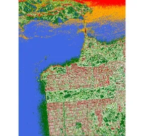
Fig. 10 The classification maps of the compactH/alpha/Wishart algorithm with the same color labels as in Fig. 9(a)
As for the latter classification scheme, we have added two steps of refining process,i.e. excluding pixels with no clear defined PSMs and cluster merging process utilizing span (the total power), to ensure the reliability of the initial Wishart classes[38]. The classification results are shown in Fig. 11.
6.2 Compact PolSAR interferometry

Fig. 11 Classification results of the m/chi/Wishart algorithm
Compact PolInSAR is also one of the research hotspot within CP technologies. Compact PolInSAR system can measure two target scattering vectors of each resolution element in the scene from two slightly different look angle in a singlepass or repeated-pass interferometric configuration. The compact polarimetric scattering vectors measured at ends 1 and 2 of the baseline, can be expressed asA four-element complex scattering target vector4can be formed by stacking theThe complete polarimetric and interferometric information of two CP acquisitions are therefore represented by a 4×4 matrix

where matricesJ11andJ22are the compact covariance matrices andJ12is the compact cross-covariance matric representative of compact PolIn-SAR configuration.
There are two main directions to process compact PolInSAR data. One is to reconstruct the quad PolInSAR data from the compact PolIn-SAR[24,25], similar to the covariance matrix expansion method introduced in Subsection 5.3.1. Another important and more typical one is to process compact PolSAR dataset directly. Once pseudo-quad-pol data is reconstructed, conventional PolInSAR methodologies can be applied. Therefore, we will only review the two typical compact PolInSAR applications stemmed from the latter research direction in this subsection.
6.2.1 Forest height estimationOne typical application of compact PolInSAR technique is the estimation of forest heights. All methods of forest heights inversion are based on the RVoG model, which is modeled as the combination of a ground contribution and a volume only contribution. The inversion consists of fitting a line through the coherences, computing the topographical phase which is the intersection of fitting line with the unit circular and computing the volume only coherence which provides the vegetation height. The key step is therefore to fit line and find the correct volume only coherence. No matter which methods, their theory basis all are the complex coherence of compact PolInSAR data, which can be expressed as

whereω1,ω2represent polarimetric projection vectors.
In Refs. [21,22], the compact polarimetric coherence locus associated with all the polarization states of the receiving antenna (a two-parameter space) were computed. Based on the coherence locus, a straight line was fitted, and then the three-stage inversion method was applied to estimate the tree heights. Detailed steps are listed as following:
(1) Synthesize many interferometric coherence values by varying the polarization of the receive antennas (varyingω1,ω2of Eq. (48)) and identify the fitting line.
(2) Identify the two intersection points between the fitting line and the circle. Choose between the two the one that is associated with the topographical phase ejφ0.
(3) Select the interferometric coherence that is furthest from the ground coherence as ejφ0γv. Remove the topographical phase and obtain the volume only coherence γv.
(4) Apply the Look-Up Table (LUT) technique to find the tree height and the attenuation.
The tree heights inversion procedure in Ref. [26] is different from those in Refs. [21,22]. In Ref. [26], the compact polarimetric coherence locus was not computed, instead, only several coherences were computed to fit the straight line. The coherence used to fit the straight line included two receiving channel coherences, unconstrained optimal coherences and maximum phase separation coherences. The maximum phase separationcoherences were used to estimate the topographical phase and initial volume decorrelation. Then volume decorrelation estimation was updated with coherence boundary extraction method. After obtaining the ground phase and the accurate volume only coherence, LUT technique was used to find the tree heights and the attenuations.
6.2.2 Compact PolInSAR target decompositionIn Refs. [28,30] a target decomposition method utilizing compact PolInSAR data is proposed. The Freeman-Durden decomposition technique was applied to the compact PolInSAR data[25]. The complex cross-correlation matrix of compact PolInSAR was decomposed into three 2×2 scattering matrices corresponding to the surface, double-bounce, and volume scattering.

Note thatfcv,fcs, andfcdare complex unknowns containing amplitude and phase center heights information.
The algorithm was validated with simulated data derived from PolSARProSim program. One simulated L-band PolInSAR forest dataset was generated corresponding to 10 m forest heights. Fig. 12(a) is the Pauli image of the simulated scenario: here we analyzed an image transect indicated by the red line. We transformed the simulated quad-pol data to compact- pol data, and then constructed the compact-pol cross-correlation observable matrixJ2. Decomposing results are shown in Fig. 12(c). The phrase ODD, DBL, and VOL stands for odd-bounce scattering, double-bounce scaffering, and volume scaffering, respectively, and VC and HC stands for circular polarization in transmission and receiving in linear (vertical or horizontal) polarization. According to the compact PolInSAR target decomposition, the amplitude and phase of each scattering mechanism were obtained. In addition, the decomposition results quite agreed with fully PolInSAR decomposition[95], which demonstrated that the compact PolInSAR also has the potential for target decomposition.
6.3 Other applications

Fig. 12 Simulated dataset Pauli decomposition image
Beside the two main applications introducedin previous subsections, other wide-swath-benefitted applications, such as soil moisture estimation[17-20], iceberg[43-45], oil-spill[46-53]and ship detection[42,45,52-55], crop classification[56-61]and sea ice surveillance[12-14,85,86]have also been carefully investigated in the latest researches. According to their investigations, comparable data processing results could be obtained with CP data comparing with those derived from quad-pol SAR data.
7 Conclusion
In this paper, we have fully reviewed the principles and applications of the HP architecture based PolSAR. As we can see, the HP architecture is actually a PolSAR system design scheme, which firstly emphasis the synthesis of transmit polarizations with two separated signal channels. Thereby, any polarization can be generated theoretically, including the circular polarizations and the slant linear polarizations required in compact polarimetry. In other words, this feature makes an HP architecture based PolSAR system possible to operate under different CP modes, which can produce classification results superior than conventional linear dual-pol modes. Moreover, if the adopted transmit polarizations have equal H and V components, as is the case with all CP modes, the HP architecture based PolSAR system will have a unique self-calibration feature. Secondly, this design scheme also emphasis that the transmitted polarization should differ from the receiving polarization basis. Thus, the range ambiguity performance of the HP architecture based PolSAR system can be improved and the swath coverage of the HP architecture based PolSAR system can be further broadened, particularly at higher incident angles, when operating under quad-pol mode. Last but not least, this design scheme actually requires very few RF hardware, which implies a less costly and more robust PolSAR system. Besides, shorter repetition intervals, in which coherent radar images are obtained, can also be reached by HP architecture based PolSAR systems due to the advantage of wider swath coverage.
Meanwhile, this paper has also pointed out the implementation difficulties of the HP architecture,i.e. the transmit distortions cannot be calibrated when the HP architecture based PolSAR system works under the dual-pol mode. Besides, the polarization adopted for transmission is also always circular. Since PolSAR data acquired with other transmit polarization may also produce favorable results in certain applications, this configuration is also regarded as one problem. In order to overcome these problems, we have proposed an improved version of the HP architecture. With the improved HP architecture, a pre-distortion technique can be applied to correct the transmit distortions. Comparing with radar systems with extra internal calibration loops, the proposed improved version requires less RF hardware. Besides, instead of just transmitting circular polarizations, a PolSAR system based on the improved HP architecture can operate with arbitrary transmit polarization configurations. This feature implies that the improved HP architecture can also support the π/4 mode and other quad-pol modes with different orthogonal transmit polarization pairs. At last, we have illustrated a prototype system based on the improved HP architecture. Associated experimental verifications are still in progress.
Acknowledgements
Each part of the HP architecture research program was contributed by: Prof. Hong Wen for the planning and organization of the whole project; Dr. Li Yang, Zhang Jing-jing for initial system design; Dr. Chen Lin, Zhang Jing-jing for CP calibration algorithm design; Dr. Chen Lin, Dr. Guo Sheng-long, and Chen Shi-qiang for CP application investigation; Chen Shi-qiang, Dr. Guo Sheng-long, and Dr. Yin Qiang for the integration and subsequent experimental verification of the improved HP architecture prototype.
References
[1]Moreira A, Prats-Iraola P, Younis M,et al.. A tutorial on synthetic aperture radar[J].IEEE Geoscience and Remote Sensing Magazine, 2013, 1(1): 6-43. doi: 10.1109/MGRS. 2013.2248301.
[2]Ouchi K. Recent trend and advance of synthetic aperture radar with selected topics[J].Remote Sensing, 2013, 5(2): 716-807. doi: 10.3390/RS5020716.
[3]Curlander J C and McDonough R N. Synthetic Aperture Radar: Systems and Signal Processing[M]. New York, NY, USA: John Wiley & Sons, Inc., 1991: 303-305.
[4]Raney R K, Freeman A, and Jordan R L. Improved range ambiguity performance in quad-pol SAR[J].IEEE Transactions on Geoscience and Remote Sensing, 2012, 50(2): 349-356. doi: 10.1109/TGRS.2011.2121075.
[5]Freeman A. A new system model for radar polarimeters[J].IEEE Transactions on Geoscience and Remote Sensing, 1991, 29(5): 761-767. doi: 10.1109/36.83991.
[6]Touzi R, Livingstone C E, Lafontaine J R C,et al.. Consideration of antenna gain and phase patterns for calibration of polarimetric SAR data[J].IEEE Transactions on Geoscience and Remote Sensing, 1993, 31(6): 1132-1145. doi: 10.1109/36.317449.
[7]Raney R K. Hybrid-polarity SAR architecture[J].IEEE Transactions on Geoscience and Remote Sensing, 2007, 45(11): 3397-3404. doi: 10.1109/TGRS.2007.895883.
[8]Raney R K. Hybrid-quad-pol SAR[C]. 2008 IEEE International Geoscience and Remote Sensing Symposium (IGARSS), Boston, USA, 2008, 4: IV-491-IV-493. doi: 10.1109/ IGARSS.2008.4779765.
[9]Souyris J C, Imbo P, Fjørtoft R,et al.. Compact polarimetry based on symmetry properties of geophysical media: The π/4 mode[J].IEEE Transactions on Geoscience and Remote Sensing, 2005, 43(3): 634-646. doi: 10.1109/TGRS. 2004.842486.
[10]Stacy N and Preiss M. Compact polarimetric analysis of X-band SAR data[C]. 6th European Conference on Synthetic Aperture Radar (EUSAR), Dresden, Germany, 2006.
[11]Nord M E, Ainsworth T L, Lee J S,et al.. Comparison of compact polarimetric synthetic aperture radar modes[J].IEEE Transactions on Geoscience and Remote Sensing, 2009, 47(1): 174-188. doi: 10.1109/TGRS.2008.2000925.
[12]Charbonneau F J, Brisco B, Raney R K,et al.. Compact polarimetry overview and applications assessment[J].Canadian Journal of Remote Sensing, 2010, 36(Suppl. 2): S298-S315. doi: 10.5589/M10-062.
[13]Dabboor M and Geldsetzer T. Towards sea ice classification using simulated RADARSAT Constellation Mission compact polarimetric SAR imagery[J].Remote Sensing of Environment, 2014, 140: 189-195. doi: 10.1016/J.RSE.2013. 08.035.
[14]Geldsetzer T, Arkett M, Zagon T,et al.. All-season compact-polarimetry C-band SAR observations of sea ice[J].Canadian Journal of Remote Sensing, 2015, 41(5): 485-504. doi: 10.1080/07038992.2015.1120661.
[15]Geldsetzer T, Charbonneau F, Arkett M,et al.. Ocean wind study using simulated RCM compact-polarimetry SAR[J].Canadian Journal of Remote Sensing, 2015, 41(5): 418-430. doi: 10.1080/07038992.2015.1104635.
[16]Denbina M and Collins M J. Wind speed estimation using C-band compact polarimetric SAR for wide swath imaging modes[J].ISPRS Journal of Photogrammetry and Remote Sensing, 2016, 113: 75-85. doi: 10.1016/J.ISPRSJPRS. 2016.01.002.
[17]Williams M L. Potential for surface parameter estimation using compact polarimetric SAR[J].IEEE Geoscience and Remote Sensing Letters, 2008, 5(3): 471-473. doi: 10.1109/ LGRS.2008.918012.
[18]Truong-Loï M L, Freeman A, Dubois-Fernandez P C,et al.. Estimation of soil moisture and Faraday rotation from bare surfaces using compact polarimetry[J].IEEE Transactions on Geoscience and Remote Sensing, 2009, 47(11): 3608-3615. doi: 10.1109/TGRS.2009.2031428.
[19]Ouellette J D, Johnson J T, Kim S,et al.. A simulation study of compact polarimetry for radar retrieval of soil moisture[J].IEEE Transactions on Geoscience and Remote Sensing, 2014, 52(9): 5966-5973. doi: 10.1109/TGRS. 2013.2294133.
[20]Ponnurangam G G, Jagdhuber T, Hajnsek I,et al.. Soil moisture estimation using hybrid polarimetric SAR data of RISAT-1[J].IEEE Transactions on Geoscience and Remote Sensing, 2016, 54(4): 2033-2049. doi: 10.1109/TGRS.2015. 2494860.
[21]Angelliaume S, Dubois-Fernandez P, and Souyris J C. Compact PolInSAR for vegetation characterisation[C]. 2007 IEEE International Geoscience and Remote Sensing Symposium (IGARSS), Barcelona, Spain, 2007: 1136-1138. doi: 10.1109/IGARSS.2007.4423003.
[22]Dubois-Fernandez P C, Souyris J C, Angelliaume S,et al.. The compact polarimetry alternative for spaceborne SAR at low frequency[J].IEEE Transactions on Geoscience and Remote Sensing, 2008, 46(10): 3208-3222. doi: 10.1109/TGRS. 2008.919143.
[23]Wilsen C B, Sarabandi K, and Lin Y C. The effect of tree architecture on the polarimetric and interferometric radar responses[C]. 1998 IEEE Geoscience and Remote Sensing Symposium (IGARSS), Seattle, WA, USA, 1998, 3: 1499-1501. doi: 10.1109/IGARSS.1998.691536.
[24]Lavalle M. Full and compact polarimetric radar interferometry for vegetation remote sensing[D]. [Ph.D. dissertation], Université Rennes 1, 2009: 95-128.
[25]Lavalle M, Solimini D, Pottier E,et al.. Compact polarimetric SAR interferometry[J].IET Radar,Sonar&Navigation, 2010, 4(3): 449-456. doi: 10.1049/IET-RSN.2009.0049.
[26]谈璐璐, 杨立波, 杨汝良. 合成孔径雷达简缩极化干涉数据的植被高度反演技术研究[J]. 电子与信息学报, 2010, 32(12): 2814-2819. Tan L L, Yang L B, and Yang R L. Investigation on vegetation height retrieval technique with compact PolInSAR data[J].Journal of Electronics&Information Technology, 2010, 32(12): 2814-2819.
[27]Arnaubec A, Roueff A, Dubois-Fernandez P C,et al.. Vegetation height estimation precision with compact PolIn-SAR and homogeneous random volume over ground model[J].IEEE Transactions on Geoscience and Remote Sensing, 2014, 52(3): 1879-1891. doi: 10.1109/TGRS. 2013.2256362.
[28]Guo S, Li Y, Yin Q,et al.. Applying the Freeman-Durden decomposition to compact polarimetric SAR Interferometry[C]. 2014 IEEE International Geoscience and Remote Sensing Symposium (IGARSS), Quebec City, Canada, 2014: 3486-3489. doi: 10.1109/IGARSS.2014.6947233.
[29]Guo S L, Li Y, and Hong W. Model-based target decomposition with π/4 mode compact polarimetry data[J].Science China:Information Sciences, 2016, 59(16): 062307. doi: 10.1007/s11432-015-5478-4.
[30]郭胜龙, 李洋, 尹嫱, 等. 基于简缩极化干涉SAR数据的森林垂直参数反演[J]. 电子信息学报, 2016, 38(1): 71-79. Guo S L, Li Y, Yin Q,et al.. Vertical parameters estimation of forest with compact polarimetric SAR interferometry data[J].Journal of Electronics&Information Technology, 2016, 38(1): 71-79.
[31]郭胜龙, 李洋, 杨士林, 等. 基于模型的π/4模式简缩极化干涉数据目标分解[J]. 电子信息学报, 2015, 37(1): 22-28. Guo S L, Li Y, Yang S L,et al.. Model-based target decomposition with π/4 mode compact polarimetric SAR interferometric data[J].Journal of Electronics&Information Technology, 2015, 37(1): 22-28.
[32]Ainsworth T L, Kelly J P, and Lee J S. Classification comparisons between dual-pol, compact polarimetric and quadpol SAR imagery[J].ISPRS Journal of Photogrammetry and Remote Sensing, 2009, 64(5): 464-471. doi: 10.1016/J.ISPRSJPRS.2008.12.008.
[33]Chen L, Cao F, and Hong W. Unsupervised classification for compact polarimetric SAR data usingm-δdecomposition, SPAN and the Wishart classifier[C]. The 2nd Asian-Pacific Conference on Synthetic Aperture Radar (APSAR) 2009, Xian, China, 2009: 742-745. doi: 10.1109/APSAR. 2009. 5374214.
[34]Chen L. Investigation on the models and methods of compact polarimetric SAR information processing[D]. [Ph.D. dissertation], Institute of Electronics, Chinese Academy of Sciences, 2013: 45-60, 69-74, 75-98.
[35]Cloude S R, Goodenough D G, and Chen H. Compact polarimetry for C-band land-use classification: a pre-study for the Canadian Radar Constellation Mission (RCM)[C]. SPIE Remote Sensing. International Society for Optics and Photonics, Edinburgh, United Kingdom, 2012: 853606-853606-14. doi: 10.1117/12.973704.
[36]Panigrahi R and Mishra A K. Unsupervised classification of scattering behaviour using hybrid-polarimetry[J].IET Radar,Sonar&Navigation, 2013, 7(3): 270-276. doi: 10.1049/IET-RSN.2012.0207.
[37]Turkar V, De S, Rao Y S,et al.. Comparative analysis of classification accuracy for RISAT-1 compact polarimetric data for various land-covers[C]. 2013 IEEE International Geoscience and Remote Sensing Symposium (IGARSS), Melbourne, VIC, Australia, 2013: 3586-3589. doi: 10.1109/IGARSS.2013.6723605.
[38]Chen S, Guo S, Li Y,et al.. Unsupervised classification for hybrid polarimetric SAR data based on scattering mechanisms and Wishart classifier[J].Electronics Letters, 2015, 51(19): 1530-1532. doi: 10.1049/EL.2015.1627.
[39]Guo S, Tian Y, Li Y,et al.. Unsupervised classification based onH/alpha decomposition and Wishart classifier for compact polarimetric SAR[C]. 2015 IEEE International Geoscience and Remote Sensing Symposium (IGARSS), Milan, Italy, 2015: 1614-1617. doi: 10.1109/IGARSS.2015. 7326093.
[40]Zhang H, Xie L, Wang C,et al.. Investigation of the capability of decomposition of compact polarimetric SAR[J].IEEE Geoscience and Remote Sensing Letters, 2014, 11(4): 868-872. doi: 10.1109/LGRS.2013.2280456.
[41]Aghabalaei A, Maghsoudi Y, and Ebadi H. Forest classification using extracted PolSAR features from compact polarimetry data[J].Advances in Space Research, 2016, 57(9): 1939-1950. doi: 10.1016/J.ASR.2016.02.007.
[42]Touzi R and Vachon P W. RCM polarimetric SAR for enhanced ship detection and classification[J].Canadian Journal of Remote Sensing, 2015, 41(5): 473-484. doi: 10.1080/ 07038992.2015.1110010.
[43]Denbina M and Collins M J. Iceberg detection using compact polarimetric synthetic aperture radar[J].Atmosphere-Ocean, 2012, 50(4): 437-446. doi: 10.1080/07055900. 2012.733307.
[44]Denbina M and Collins M J. Iceberg detection using analysis of the received polarization ellipse in compact polarimetry[C]. 2014 IEEE International Geoscience and Remote Sensing Symposium (IGARSS), Quebec City, Canada, 2014: 266-269. doi: 10.1109/IGARSS.2014.6946408.
[45]Denbina M, Collins M J, and Atteia G. On the detectionand discrimination of ships and icebergs using simulated dual-polarized RADARSAT constellation data[J].Canadian Journal of Remote Sensing, 2015, 41(5): 1-17. doi: 10.1080/ 07038992.2015.1104630.
[46]Salberg A B, Rudjord O, and Solberg A H S. Oil spill detection in hybrid-polarimetric SAR images[J].IEEE Transactions on Geoscience and Remote Sensing, 2014, 52(10): 6521-6533. doi: 10.1109/TGRS.2013.2297193.
[47]Li Y, Zhang Y, Chen J,et al.. Improved compact polarimetric SAR quad-pol reconstruction algorithm for oil spill detection[J].IEEE Geoscience and Remote Sensing Letters, 2014, 11(6): 1139-1142. doi: 10.1109/LGRS.2013.2288336.
[48]Yin J, Moon W, and Yang J. Model-based pseudo-quad-pol reconstruction from compact polarimetry and its application to oil-spill observation[J].Journal of Sensors, 2015. doi: 10.1155/2015/734848.
[49]Nunziata F, Migliaccio M, and Li X. Sea oil slick observation using hybrid-polarity SAR architecture[J].IEEE Journal of Oceanic Engineering, 2015, 40(2): 426-440. doi: 10.1109/JOE.2014.2329424.
[50]Li Y, Lin H, Zhang Y,et al.. Comparisons of circular transmit and linear receive compact polarimetric SAR features for oil slicks discrimination[J].Journal of Sensors, 2015. doi: 10.1155/2015/631561.
[51]Li H, Perrie W, He Y,et al.. Analysis of the polarimetric SAR scattering properties of oil-covered waters[J].IEEE Journal ofSelected Topics in Applied Earth Observations and Remote Sensing, 2015, 8(8): 3751-3759. doi: 10.1109/ JSTARS.2014.2348173.
[52]Shirvany R, Chabert M, and Tourneret J Y. Ship and oilspill detection using the degree of polarization in linear and hybrid/compact dual-pol SAR[J].IEEE Journal ofSelected Topics in Applied Earth Observations and Remote Sensing, 2012, 5(3): 885-892. doi: 10.1109/JSTARS.2012.2182760.
[53]Yin J, Yang J, Zhou Z S,et al.. The extended bragg scattering model-based method for ship and oil-spill observation using compact polarimetric SAR[J].IEEE Journal ofSelected Topics in Applied Earth Observations and Remote Sensing, 2015, 8(8): 3760-3772. doi: 10.1109/JSTARS.2014. 2359141.
[54]Atteia G E and Collins M J. On the use of compact polarimetry SAR for ship detection[J].ISPRS Journal of Photogrammetry and Remote Sensing, 2013, 80: 1-9. doi: 10.1016/J.ISPRSJPRS.2013.01.009.
[55]Yin J and Yang J. Ship detection by using the M-Chi and M-Delta decompositions[C]. IEEE International Geoscience and Remote Sensing Symposium (IGARSS) 2014, Quebec City, Canada, 2014: 2738-2741. doi: 10.1109/IGARSS. 2014.6947042.
[56]Ballester-Berman J D and Lopez-Sanchez J M. Time series of hybrid-polarity parameters over agricultural crops[J].IEEE Geoscience and Remote Sensing Letters, 2012, 9(1): 139-143. doi: 10.1109/LGRS.2011.2162312.
[57]Brisco B, Li K, Tedford B,et al.. Compact polarimetry assessment for rice and wetland mapping[J].International Journal of Remote Sensing, 2013, 34(6): 1949-1964. doi: 10.1080/01431161.2012.730156.
[58]Lopez-Sanchez J M, Vicente-Guijalba F, Ballester-Berman J D,et al.. Polarimetric response of rice fields at C-band: Analysis and phenology retrieval[J].IEEE Transactions on Geoscience and Remote Sensing, 2014, 52(5): 2977-2993. doi: 10.1109/TGRS.2013.2268319.
[59]Yang Z, Li K, Liu L,et al.. Rice growth monitoring using simulated compact polarimetric C band SAR[J].Radio Science, 2014, 49(12): 1300-1315. doi: 10.1002/2014RS005498.
[60]Uppala D, Kothapalli R V, Poloju S,et al.. Rice crop discrimination using single date RISAT1 hybrid (RH, RV) polarimetric data[J].Photogrammetric Engineering&Remote Sensing, 2015, 81(7): 557-563. doi: 10.14358/PERS.81.7.557.
[61]Xie L, Zhang H, Wu F,et al.. Capability of rice mapping using hybrid polarimetric SAR data[J].IEEE Journal of Selected Topics in Applied Earth Observations and Remote Sensing, 2015, 8(8): 3812-3822. doi: 10.1109/JSTARS.2014. 2387214.
[62]Raney K, Spudis P D, Bussey B,et al.. The lunar mini-RF radars: Hybrid polarimetric architecture and initial results[J].Proceedings of the IEEE, 2011, 99(5): 808-823. doi: 10.1109/JPROC.2010.2084970.
[63]Misra T and Kirankumar A S. RISAT-1: Configuration and performance evaluation[C]. 2014 XXXIth URSI General Assembly and Scientific Symposium (URSI GASS), Beijing, China, 2014: 1-4. doi: 10.1109/URSIGASS.2014.6929612.
[64]Kankaku Y, Osawa Y, Suzuki S,et al.. The overview of the L-band SAR onboard ALOS-2[C]. 2009 Proceedings of Progress in Electromagnetics Research Symposium (PIERS), Moscow, Russia, 2009: 735-738.
[65]Touzi R and Charbonneau F. Requirements on the calibration of hybrid-compact SAR[C]. 2014 IEEE International Geoscience and Remote Sensing Symposium (IGARSS), Quebec City, Canada, 2014: 1109-1112. doi: 10.1109/IGARSS.2014.6946623.
[66]Thompson A A. Overview of the RADARSAT constellation mission[J].Canadian Journal of Remote Sensing, 2015, 41(5): 401-407. doi: 10.1080/07038992.2015.1104633.
[67]Raney R K. DESDynI adopts hybrid polarity SAR architecture[C]. 2009 IEEE Radar Conference, Pasadena, USA, 2009: 1-4. doi: 10.1109/RADAR.2009.4977046.
[68]Donnellan A, Rosen P, Graf J,et al.. Deformation, ecosystem structure, and dynamics of ice (DESDynI)[C]. 2008 IEEE Aerospace Conference, Big Sky, MT, USA, 2008: 1-13. doi: 10.1109/AERO.2008.4526249.
[69]Putrevu D, Das A, Vachhani J G,et al.. Chandrayaan-2 dual-frequency SAR: Further investigation into lunar water and regolith[J].Advances in Space Research, 2016, 57(2): 627-646. doi: 10.1016/J.ASR.2015.10.029.
[70]Freeman A, Dubois-Fernandez P, and Truong-Loï M L. Compact polarimetry at longer wavelengths-calibration[C]. 7th European Conference on Synthetic Aperture Radar (EUSAR), Friedrichshafen, Germany, 2008: 1-4.
[71]Guo S, Zhang J, Li Y,et al.. Effects of polarization distortion at transmission and faraday rotation on compact polarimetric SAR system and decomposition[J].IEEE Geoscience and Remote Sensing Letters, 2015, 12(8): 1700-1704. doi: 10.1109/LGRS.2015.2420116.
[72]Tan H and Hong J. Correction of transmit crosstalk in reconstruction of quad-pol data from compact polarimetry data[J].IEEE Geoscience and Remote Sensing Letters, 2015, 12(5): 1051-1055. doi: 10.1109/LGRS.2014.2377491.
[73]Freeman A. Calibration of linearly polarized polarimetric SAR data subject to Faraday rotation[J].IEEE Transactions on Geoscience and Remote Sensing, 2004, 42(8): 1617-1624. doi: 10.1109/TGRS.2004.830161.
[74]Raney R K. Comments on hybrid-polarity SAR architecture[C]. 2007 IEEE International Geoscience and Remote Sensing Symposium (IGARSS), Barcelona, Spain, 2007: 2229-2231. doi: 10.1109/IGARSS.2007.4423282.
[75]McKerracher J R, Sequeira H B, Raney R K,et al.. Mini-RF calibration, a unique approach to on-orbit synthetic aperture radar system calibration[C]. The 41st Lunar and Planetary Science Conference, Woodlands, TX, USA, 2010: 2352-2353.
[76]Wright P A, Quegan S, Wheadon N S,et al.. Faraday rotation effects on L-band spaceborne SAR data[J].IEEE Transactions on Geoscience and Remote Sensing, 2003, 41(12): 2735-2744. doi: 10.1109/TGRS.2003.815399.
[77]Truong-Loï M L, Dubois-Fernandez P, Pottier E,et al.. Potentials of a compact polarimetric SAR system[C]. 2010 IEEE Geoscience and Remote Sensing Symposium (IGARSS), Honolulu, HI, USA, 2010: 742-745. doi: 10.1109/IGARSS.2010.5649036.
[78]Chen J and Quegan S. Calibration of spaceborne CTLR compact polarimetric low-frequency SAR using mixed radar calibrators[J].IEEE Transactions on Geoscience and Remote Sensing, 2011, 49(7): 2712-2723. doi: 10.1109/TGRS. 2011.2109065.
[79]陈琳, 张晶晶, 李洋, 等. 单发双收SAR系统通用极化定标算法[J]. 雷达学报, 2012, 1(3): 323-328. Chen L, Zhang J J, Li Y,et al.. General calibration algorithm for single-transmitting-dual-receiving polarimetric SAR system[J].Journal of Radars, 2012, 1(3): 323-328.
[80]Wang Y, Ainsworth T L, and Lee J S. Assessment of system polarization quality for polarimetric SAR imagery and target decomposition[J].IEEE Transactions on Geoscience and Remote Sensing, 2011, 49(5): 1755-1771. doi: 10.1109/ TGRS.2010.2087342.
[81]Lee J S and Pottier E. Polarimetric Radar Imaging: From Basics to Applications[M]. New York, CRC Press, 2009: 27-28, 36-37, 59-63.
[82]Sabry R and Vachon P W. A unified framework for general compact and quad polarimetric SAR data and imagery analysis[J].IEEE Transactions on Geoscience and Remote Sensing, 2014, 52(1): 582-602. doi: 10.1109/TGRS.2013. 2242479.
[83]Cloude S R, Goodenough D G, and Chen H. Compact decomposition theory[J].IEEE Geoscience and Remote Sensing Letters, 2012, 9(1): 28-32. doi: 10.1109/LGRS.2011. 2158983.
[84]PolSAR Pro 5.0 Software, European Space Agency. [OL].https://earth.esa.int/web/polsarpro/home, 2016.10.13.
[85]Eltoft T, Doulgeris A P, and Grahn J. Model-based polarimetric decomposition of Arctic sea ice[C]. 10th European Conference on Synthetic Aperture Radar (EUSAR), Berlin, Germany, 2014.
[86]Espeseth M M, Brekke C, and Anfinsen S N. Hybrid-polarity and reconstruction methods for sea ice with L-and CBand SAR[J].IEEE Geoscience and Remote Sensing Letters, 2016, 13(3): 467-471. doi: 10.1109/LGRS.2016. 2519824.
[87]Espeseth M M. Synthetic aperture radar compact polarimetry for sea ice surveillance[D]. [Master dissertation], The Arctic University of Norway, 2015: 85-124.
[88]Raney R K. Dual-polarized SAR and stokes parameters[J].IEEE Geoscience and Remote Sensing Letters, 2006, 3(3): 317-319. doi: 10.1109/LGRS.2006.971746.
[89]Raney R K, Cahill J T S, Patterson G,et al.. The m-chi decomposition of hybrid dual-polarimetric radar data[C]. 2012 IEEE International Geoscience and Remote Sensing Symposium (IGARSS), Munich, Germany, 2012: 5093-5096. doi: 10.1109/IGARSS.2012.6352465.
[90]Raney R K, Cahill J T S, Patterson G,et al.. The m-chi decomposition of hybrid dual-polarimetric radar data with application to lunar craters[J].Journal of Geophysical Research:Planets, 2012, 117(E12). doi: 10.1029/2011 JE003986.
[91]Guo R, Liu Y B, Wu Y H,et al.. Applying H/αdecomposition to compact polarimetric SAR[J].IET Radar,Sonar&Navigation, 2012, 6(2): 61-70. doi: 10.1049/ IETRSN.2011.0007.
[92]Freeman A and Durden S L. A three-component scattering model for polarimetric SAR data[J].IEEE Transactions on Geoscience and Remote Sensing, 1998, 36(3): 963-973. doi: 10.1109/36.673687.
[93]Liu M, Zhang H, and Wang C. Three-component scattering model for compact polarimetric SAR data[J].Chinese Journal of Radio Science, 2012, 27(2): 365-371.
[94]Guo R, He W, Zhang S,et al.. Analysis of three-component decomposition to compact polarimetric synthetic aperture radar[J].IET Radar,Sonar&Navigation, 2014, 8(6): 685-691. doi: 10.1049/IET-RSN.2013.0114.
[95]Ballester-Berman J D and Lopez-Sanchez J M. Applying the Freeman-Durden decomposition concept to polarimetric SAR interferometry[J].IEEE Transactions on Geoscience and Remote Sensing, 2010, 48(1): 466-479. doi: 10.1109/TGRS.2009.2024304.

洪 文(1968-),女,研究员,1997年毕业于北京航空航天大学,获工学博士学位。研究经历包括北京航空航天大学电子工程系副教授、德国宇航院雷达与微波技术所(DLR-HF)客座研究员等,现为中国科学院电子学研究所研究员,博士生导师,院优秀教师获得者,中科院“百人计划”。主要研究方向为极化/极化干涉SAR处理及应用、3维SAR信号处理、圆迹SAR信号处理以及稀疏微波成像技术。
Author Introduction
Hong Wen was born in Shaanxi, China, in 1968. She received the M.S. degree in electronic engineering from Northwestern Polytechnical University, Xi’an, China, in 1993 and the Ph.D. degree from Beihang University, Beijing, China, in 1997.
From 1997 to 2002, she was a Faculty Member in signal and information processing with the Department of Electrical Engineering, Beihang University. In between, she was a Guest Scientist with the DLR-HF, Wessling, Germany, from 1998 to 1999 for one year. Since 2002, she has been a Scientist with the Science and Technology on Microwave Imaging Laboratory and a Supervisor of the graduate student program in the Institute of Electronics, Chinese Academy of Sciences, Beijing. Her main research interests include polarimetric/polarimetric interferometric Synthetic Aperture Radar (SAR) data processing and application, 3-D SAR signal processing, circular SAR signal processing, SAR polarimetry application, and sparse microwave imaging with compressed sensing.
洪文. 基于混合极化架构的极化SAR:原理与应用[J]. 雷达学报, 2016, 5(6): 573-595.
10.12000/JR16074
10.12000/ JR16074.
CLC index:TN958
Reference format:Hong Wen. Hybrid-polarity architecture based polarimetric SAR: Principles and applications[J].Journal of Radars, 2016, 5(6): 573-595. DOI: 10.12000/JR16074.