On the Tactile Sensing Based on the Smart Materials
2015-12-12LigiaMunteanuDanDumitriuVeturiaChiroiuCornelBrisanMirceaBaraandDoinaMarin
Ligia Munteanu,Dan Dumitriu,Veturia Chiroiu,Cornel Bri¸san,Mircea Baraand Doina Marin
On the Tactile Sensing Based on the Smart Materials
Ligia Munteanu1,Dan Dumitriu1,Veturia Chiroiu1,Cornel Bri¸san2,Mircea Bara2and Doina Marin1
A flexible finger with muscles made of Nitinol wires and the skin made of auxetic material is analyzed from the tactile sensing point of view.The recognizing of the shape and texture of 3D objects is performed by simulation the action of an array of nanopiezotronic transistors integrated into the skin.The array of nanopiezotronic transistors makes possible the detection of the pressure-induced changes in the auxetic skin.The shape and texture of the objects is best estimated by determining the surface and texture as an n-ellipsoid defined by 12 parameters.An inverse problem is solved in order to find these parameters from the condition that the n-ellipsoid best fits the set of data points probed by touch with the finger.
Nitinol,auxetic material,tactile sensing,shape and texture of 3D objects.
1 Introduction
Robotic tactile sensing involves techniques for knowledge transfer from human to robot[Dahiya and Valle(2013)].The robotic tactile sensing in touching,grasping and manipulating of the objects is the base for exploring and differentiating the objects from one another with respect to shape,surface texture,stiffness,temperature etc.[Ernst and Banks(2002);Shikida et al.(2003);Fearing(1990)].
The experiments involving stroking and vertical indentation of the skin,with the force equal to that exerted by humans during natural manipulation(15–90g/m),indicate that the object shape and orientation are signaled by spatio-temporal functions which characterize the mechanoreceptors of the skin[Weinberg et al.(2005);Rucci and Bajcsy(1995);Liu et al.(2005);Goodwin et al.(1997);Ju et al.(2014)].Geometrically and structurally,the skin is a complex mechanical system supported by the deformable system of muscles and tendons.The stiffness of various skin layers significantly varies with epidermis being considerably stiffer than the dermis(the Young’s modulus of base layer,i.e.the epidermis is 10–10000 times that of the dermis).Skin acts as a multilayered,nonlinear,nonhomogeneous and viscoelastic medium in order to convert the surface indentation into stress and strain fields.The thickness of skin in adult humans vary between 0.6–0.8 mm and the Young’s modulus is around 4×10⁵ N/m2[Schiffman(2001);Escoffier et al.(1989)].
In order to mimic the tactile sensing capabilities of the human skin,a flexible finger with the muscles and skin made of Nitinol(NiTi)wires and auxetic material,respectively,is considered in this paper.The robotic shape detection of the objects within the contact area(7–12 mm)of the fingertip may be realized by using the interface piezotronic effect[Wu et al.(2013)].The piezotronic effect arises as a result of the polarization of non-mobile ions in the crystal,unlike the piezoresistive effect which results from a change in band gap,charge carrier density,or density of states in the conduction band of the strained semiconductor material.Therefore,the piezoresistive effect is a symmetric volume effect without polarity,whereas the piezotronic effect is an interface effect that asymmetrically modulates local contacts at different terminals of the device because of the polarity of the piezoelectric potential[Wang(2010,2012a,b,2013);Zhang et al.(2011)].
Using the piezoelectric semiconductor nanowires that typically have wurtzite and zinc blend structures(such as ZnO and GaN),a piezotronic transistor design was introduced[Zhou et al(2008);Wu et al.(2010);Chen et al.(2012)]that has a two terminal metal-semiconductor-metal structure and whose charge carrier transport is modulated by the piezoelectric polarization charge–induced inner-crystal potential in the nanowires at the contacts.
As mentioned above,the muscles are made of NiTi wires.The phase change in the NiTi wires is achieved by heat exchange with a heat source and a heat sink.The actuation frequency of the NiTi wires is only dependent on the rate of heat transfer with its surroundings.The heat transfer mechanism for most Nitinol wires are based on resistive heating and cooling with forced convection or natural convection.Because this is an inefficient heat exchange mechanism[Boyd and Lagoudas(1994)]which requires the use of electrical power,we chose the semiconductors for which Peltier effect has shown high actuation frequency[Bhattcharyya et al.(1995)].In other words,we use the forced convection heating and cooling to actuate the NTi wires.This can overcome the low energy density resistive heating systems and the low efficiency of the thermoelectric heat transfer mechanism,even though it should need additional devices such as a pump and valves[Rediniotis et al.(2002)].
The cyclic behavior of NiTi wires can be described by using the Bouc-Wen model coupled to the intrinsic time measure,other than the clock time which governs the behavior of the materials[Chiroiu et al.(2015)].As a consequence,the thermodynamic admissibility of the Bouc–Wen model is provided by the endochronic theory of plasticity.The role of the intrinsic time measure is described by capturing the stiffness and strength degradation and the opposite phenomena.Such behavior is due to the permanent strains addition of the residual martensite and alterations in the properties of the texture during the phase transformation
Finally,as mentioned above,the skin is made by auxetic material.By definition,an auxetic material expands in all directions when pulled in one direction and this behavior does not contradict the classical theory of elasticity[Love(1944)].According to this theory,the variations of the Poisson’s ratio range from-1 to 0.5 for 3D isotropic materials,and from-1 to 1 for 2D isotropic systems.For anisotropic materials,the values of the Poisson’s ratio could be larger in magnitude.A negative Poisson’s ratio allows for the existence,in the orthogonal lateral directions,of positive Poisson’s ratios up to the stability limit 2 for cubic crystals[Munteanu et al.(2014);Baughman et al.(1998);Alderson et al.(1997)].Conventional foam exhibits pores with an average diameter of around 1mm,while the auxetic foam has a possible average diameter of a few micrometers or even nanometers.Processing manufacturing techniques of auxetic materials can control various features of the pore shapes and is performed by a compression process[Chan and Evans(1997);Munteanu et al.(2008,2012);Scarpa et al.(2004);Bezazi and Scarpa(2007)].The measured density of the auxetic foam was 0.118g/cm3.The conventional foam has a positive Poisson’s ratio(0.25)for a compressive strain of 10%,which decreases sharply with the increase of the compressive loading,to become slightly negative for a tensile strain ranging from 60 to 80%.The auxetic foam exhibits a negative Poisson’s ratio(-0.185)for a compressive strain ranging from 10 to 25%,showing a sharp increase for an increasing compressive strain,reaching then a zero value for a compressive strain of 55%and a positive Poisson’s ratio(1.33)for a compressive strain of 80%.
A properly auxetic version of the conventional foam is constructed by spatial compression according to[Munteanu et al.(2008,2012)]and a 3D array of piezotronic transistors are incorporated into internal pores in order to convert mechanical stimuli applied to the foam into local electronic controlling signals[Wu et al(2013)].The transistors consist in a matrix of vertical zinc oxide nanowires which are active to detect the pressure and forces for tactile imaging.The auxetic material coupled with the array of nanopiezotronic transistors is described as an elastic Cosserat material with internal degree of freedom[33-36].
The paper is organized as follows:Section 2 is devoted to solving of the inverse problem of determining the set of parameters for reconstructing the shape and texture of a 3D object.The condition that the n-ellipsoid best fits the set of data points probed by touch with the finger ensures the uniqueness of the solution.Section 3 summarizes the results.
The last Section is devoted to Conclusions,and the Appendix presents the set of equations for the finger motion.
2 Inverse Problem
Let us consider a flexible finger modeled as a cylindrically rod of length L=6cm and radius R=0.5cm,with three embedded Nitinol wires(yellow)in an aluminum matrix,at uniform absolute temperature T0(Figure 1).The NiTi wire has the length L and radius r,and are placed in a parallel arrangement to form the vertices of an equilateral triangle.The x-axis has the distal direction,the y-axis the radial(reference)direction,and z-axis the tangential direction.The rod is covered with a thin layer of auxetic material(red colour)representing the skin of the finger.
Both the matrix and the NiTi wires are assumed to be initially straight at t=0 and T0=33◦C.The NiTi wires are heated above the austenitic start temperature by passing an electrical current,and the deflected beam tends to return to the initial configuration.The NiTi alloy acts as an actuator transforming electrical energy into mechanical energy,annihilating the deformed shape of the rod.Topological view of the skin with hexagonal pores and the nanowires(red circle)is shown in Figure 2.

Figure 1:A flexible finger.
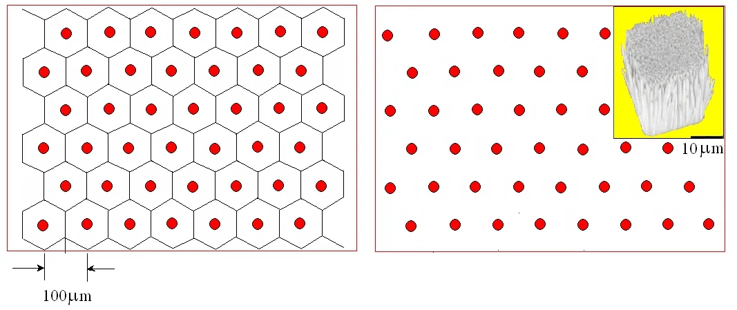
Figure 2:Topological view of the auxetic skin with hexagonal pores where the nanowires are positioned(red circle).
The operation of the gripper finger relies on the elastic deformation of three embedded NiTi wires(55%Ni,45%Ti)in an aluminum matrix.Using a different force in each NiTi wire a range of extension forces causing the finger to bend according to the constraints provided by the end plate.The larger the force,the larger the resulting finger tip deflection.In addition to bending,the triangular arrangement enables the direction of fingertip movement to be controlled.
The fundamental equations for NiTi wires are written in the spirit of Brocca et al.(2002);Otsuka and Wayman(1998);Boyd and Lagoudas(1994);Shu et al.(1997);Chiroiu and Munteanu(2003);Chiroiu et al.(2003).The fundamental equations for auxetic skin are written in the spirit of Eringen and Suhubi(1964);Eringen(1966a,b,1968);Mindlin (1964,1965); Gauthier(1982);Wang(2012)and Marin et al.(2014)..
The finger motion is described by a complex set of equations containing the aluminum equations,the NiTi wires(muscles)equations,the equations of the auxetic skin coupled with the ZnO nanowires,the conditions on the interfaces between aluminum-NiTi wires,aluminum-auxetic material,NiTi wires-auxetic material,auxetic material-ZnO nanowires,boundary conditions and initial conditions.These equations are presented in Appendix.
We assume that a finger is used to probe an object to detect its shape and the texture.The array of nanopiezotronic transistors makes possible the detection of the pressure-induced changes in the auxetic skin.
Although it is difficult to detect the shape of the object only with one finger,we still consider this variant for simulation the detection of the shape of objects with well-defined geometry such as balls or eggs.Instead,the texture can be detected using a single finger.To detect both the shape and texture,the finger can walk,rub and rotate on the surface of the object until a control parameter reaches a value proposed by algorithm.
Two simultaneously distinct system of coordinates are introduced:a fixed system with origin O and axes Ox1,Ox2,Ox3,in which a point belonging to the surface of the object is defined by(x1,x2,x3)≡(x,y,z)and a present system with origin in arbitrary centre O′coordinates xG,yG,zGof the object.Axesare determined from the finger-to-finger,and sweep directions respectively.We suppose that the object rotates about the verticalIn this system a point belonging to the surface of the object is defined by() ≡.The orientation of the axes(usually randomly oriented)is determined by the angle ψ .The transformation from(x′,y′,z′)to(x,y,z)is given by

where Rijis the rotation matrix
R=R(z,ϕ)R(x,θ)R(z,ψ),

and u the translation vector.The method for acquiring data is simulated to be capable of obtaining sufficiently accurate data.The estimation of the shape parameters of the surface is made for non-perturbed data and artificially perturbed data introduced by multiplication of the data values by 1+r,r being random numbers uniformly distributed in[−ε,ε].In this paper we consider ε=10−3.
The algorithm for reconstructing of the shape and the texture of the surface is as follows:
1.Track the surface using the finger and record the information required to determine the contact positions.This step is simulated to obtain a high number of 3D contact points in the system of coordinates(x′,y′,z′).M points along the surface are probed with the finger.Calculate the set of 12 shape parameters that define the surface Γsuch that the n-ellipsoid best fits the set of data points,by using a global volumetric deformation technique called FFD and a genetic algorithm[Asano et al.(2009);Fujiki et al.(2006)].
2.Determine the best approximating shape of the object.
3.Determine the best approximating texture of the object.
The approximating texture of the object means to describe the structures contained in textures.The microstructure and its arrangement in the texture are regarded as fundamental entities.The texture is recognized as a repetitive pattern[Chang et al.(2014)].
The model considered here is to determine the shape and texture of an unknown surface Γ of the object by using an n-ellipsoid.The goal of the inverse problem is to find the set of parameters(shape and texture parameters)that define the surface Γ such that the n-ellipsoid best fits the set of data points obtaining by the finger touching.The n-ellipsoid is defined by 12 parameters di,i=1,2,...,12:arbitrary center coordinates xG,yG,zG,principal axes a,b,c,the principal directions defined by Euler angles ξ,ψ,ζ,the exponent n and two positive numbers p and q needed to define the texture indicator J(I)

where I is a partition indicator subjected to I(Pi)=0 for any Pi(xi,yi,zi),i=1,...,M belonging to the surface of this object,and I(Pi)=1 otherwise.X is a matrix with coordinates of the model points.The weight function w is defined at every point Pi[Couprie et al.(2011)].The advantage of this model is the small number of parameters needed to represent the shape and texture of an 3D object.
The surface Γ is defined as the image of the unit n-sphere S of equation

where rij=rij(ξ,ψ,ζ)are the components of the rotation,which transforms the coordinate axes into the principal axes of the ellipsoid.These components are given by(2)by replacing θ with ξ,and ϕ with ζ.For n=2(3)yields the usual unit sphere and for n=∞ the unit cube of vertices(±1,±1,±1).By using(4)and(5)the unit sphere and the unit cube are respectively transformed into ellipsoids and boxes,with arbitrary center,size and orientation.
We refine the representation of the data using a global volumetric deformation technique called FFD[Bardinet et al.(1995);Bonnet(1993) ;Sederberg and Parry(1986)].The deformation of the box is given by the pressure-induced changes in the auxetic skin.This characteristic feature allows us to represent 3D data by a model defined by 12 parameters.An FFD is a mapping from R3to R3,defined by the tensor product of trivariate Bernstein polynomials.
The principle of FFDs is as follows: the n-ellipsoid is embedded in a 3D box.Inside this box,a volumetric grid of points is defined,which links the box to the object(by the trivariate polynomial which defines the deformation function).This can be written in a matrix form X =BP, where Bis the deformation matrix ND×NP(ND is the number of points on the discretized n-ellipsoid and NP is the number of control points of the grid),P is a matrix NP which contains coordinates of the control points and X is a matrix ND with coordinates of the model points.The box is then deformed by the displacement of its lattice,and the position and the texture pattern of each point of the real object is computed.The force Fjacting by the finger on each point j into the n-ellipsoid is given by

where cjand kjare stiffness and damping coefficients associated to the point j,and sjare displacement functions furnished by the inverse technique.These functions are used to reconstruct the cross-sectional slices of the image of the object.
Now we need to solve the following inverse problem:first compute a displacement field δX between the n-ellipsoid and M point data,and then,after inserting the n-ellipsoid into 3D box,search for the deformation δPof this box which will best minimize the displacement field δX

The partition indicator I is a solution of(8).The deformation of the box is given by the strain given by the pressure-induced changes in the skin and I is the partition indicator.
In other words,the shape and texture of the object is classically sought as the minimizer of some distances J(Γ)+J(I)between the measured data and the computed n-ellipsoid data.To represent 3D data with our model,we use an iterative two-step algorithm:
Step 1:Computation of the displacement field between the previous estimation Xnand its projection on data Xan,δXnsuch as

Step 2:Computation of the control points Pn+1by minimization of||BP−Xan||2.Computation of the deformed model

Stop test on the least-squares error
The quantity P0is defined as a uniformly spaced parallelepiped box of control points and X0=BP0represents the set of points of the initial discretized n-ellipsoid.The method is performed in simulation on cylindrical,spherical and other objects.The best results in terms of accuracy and computational efficiency are found to be obtained using a genetic algorithm.As the same n-ellipsoid can result from many combinations of Euler angles and permutations of principal axes,it is difficult to measure the accuracy of the identification of Γ by means of comparison of the identified parameters di,1=1,...,12 with those defining the“true”Γ and used to compute the simulated data.Instead,the relative errors εV,εA,εIfor the volume,boundary area and geometrical inertia tensor(with respect to the fixed coordinates Ox1x2x3)are computed.
The indicator εIis very sensitive to the orientation of Γ in space,together with the ratio Jn/J0,where Jn=J(Γn)and Γnis the current Γ after the n−th iteration of the minimization process.
Expressions of indicators εV,εA,εIin terms of boundary integrals are as follows[Bonnet(1993)]

The number of iterations of genetic algorithm,the values of Jfinal/J0,εV,εA,εIand the least square error||BP−X||are displayed in table 1 for five objects for different sizes for the box of control points,in the case of non-perturbed data.
3 Results
Consider a damaged a graphite plate of length 9cm.height 5cm and thickness 1cm(figure 3).The material is strongly anisotropic and damages make the texture to contain shallows,cracks and bumps.Therefore the finger will have to touch the material along 25 arbitrary paths shown in figure 4.If results require,the path traveled by the finger will have to get thicker where the texture is difficult.The finger walks without press the surface of the object with the velocity of 1cm/sec.The surface irregularities,elevations and simples not exceed the limit of the spatial resolution of the sensor.
The contact can be identified by checking the minimum distance between bodies[Karnopp(1985);Munteanu et al.(2015)]

where r1and r2are the position vectors of two points belonging to the tire and the road,respectively,and f1and f2are bounding surface constraints.The interference distance is defined as

where d is the interference distance and e1and e2are the unit vectors.
Three problems are important to be discussed here,i.e.the modeling of the unknown contact domains between the finger and the surface of the object,the contact and the friction forces in the contact domain.
To shape of the unknown contact domain Dcis taken as a superellipse defined by a Lamé curve[Munteanu et al.(2015)]

where x and y define the envelope of the contact area,a is half of the contact length,and b is half of the contact width(radii of the oval shape are depending of time),and n the power of the ellipsoid.The advantage of the Lamé curve consists in the effect of n to rounding the sharp corners.It provides a smooth transition between the oval and the rectangle shape.

Figure 3:A damaged graphite plate.

Figure 4:The finger tracking the plate.To the left the trajectories of the finger are shown.
The parametric representation of(16)is given by


Table 1:Dimensions of the contact patches for arbitrary paths.
In what concerns the contact force,the indentation δ is the principal factor in defining it Fc=f(δ,˙δ).A particular form is given by[59]

with k and˜b constants depending on the material and geometry.
We consider that the friction Ftoccurring at the contact point during sticking is defined as[Johnson(1985)]

where δtis the tangential component of displacement at the contact point,due to the tangential loadings,and ktis the tangential stiffness which is determined by the geometry and the material of the contacting objects.

Figure 5:The maximum pressure distribution along different paths.

Figure 6:Some arbitrary cross-sectional slices of the image of the object.
The contact domain Dcis unknown and it is modeled as a superellipse shape defined by(16).Table 1 shows the characteristics of the contact patches identified for arbitrary chosen paths 3,4,6,7,14,15,20 and 21 for touch forces of 0.04,0.06,0.07 and 0.09 N,respectively.Some arbitrary cross-sectional slices of the image of the object furnished by the inverse technique are shown in figure 6.These slices are constructed by using the displacement functions sjin each pointj belonging to discretized n-ellipsoid.The estimation of Jfin/J0, εV, εAand εIwith respect to the size of the FFD is shown in table 2.For the object,the numbers of points ND=80 and NP=51 are acceptable for a good accuracy if we use boxes of different size.The least square error||BP−X||is 0.05-1.4%for non-perturbed data and 3-8.3%for perturbed data.The numerical solution of the inverse problem hence behaves well with respect to perturbed data.This is probably a consequence of the fact that unknown geometry is described using only 12 parameters.

Table 2:Results for non-perturbed and perturbed data.
4 Conclusions
The aim of this work is to present a virtual experiment concerning the recognizing of the shape and texture of a 3D object performed by simulation the action of an array of nanopiezotronic transistors integrated into the skin.A flexible finger with the muscles made of Nitinol wires and the skin made of auxetic material is considered.The array of nanopiezotronic transistors makes possible the detection of the pressure-induced changes in the auxetic skin.The shape and texture of the 3D object is best estimated by determining the surface and texture of the object as an n-ellipsoid defined by 12 parameters.An inverse problem is solved in order to find these parameters from the condition that the n-ellipsoid best fits the set of data points probed by touch with the finger.
Acknowledgement: The authors gratefully acknowledge the financial support of the National Authority for Scientific Research ANCS/UEFISCDI through the project PN-II-ID-PCE-2012-4-0023 Contract nr.3/2013 and the project PN-II-PTPCCA-2011-3.1-0190 Contract nr.149/2012.The authors acknowledge the similar and equal contributions to this article.
Appendix
The finger motion is described by a complex set of equations containing the aluminum equations,the NiTi wires(muscles)equations,the equations of the auxetic skin coupled with the ZnO nanowires,the conditions on the interfaces between aluminum-NiTi wires,aluminum-auxetic material,NiTi wires-auxetic material,auxetic material-ZnO nanwires,boundary conditions and initial conditions.Since a nanopiezotronic transistor involves a semiconductor that is piezoelectric,the fundamental governing equations for both semiconductor and piezoelectric theories are required.The basic equations for piezotronics are electrostatic equations,current–density equations,and continuity equations,which describe the static and dynamic transport behavior of the charge carriers in semiconductors,as well as the piezoelectric equations,which describe the piezoelectric behavior of the material under dynamic strains.
We use the summation convection throughout.A superposed dot denotes differentiation with respect to time while a comma is used for material derivatives.The usual Einstein summation convention for repeated indices is used and the comma denotes differentiation with respect to spatial coordinates and a superposed dot indicates the time rate.
1.The constitutive law for the isotropic aluminum rod is

where σijare components of the stress tensor, εij=components of the strain tensor,uithe components of displacements,T absolute temperature,T0initial temperature,constants of the aluminum,βal=2µal)αal,with αalthe coefficient of linear thermal expansions.
The heat equation for the isotropic aluminum rod is given by

2.The constitutive law for NiTi wires are

where i,j,k=1,2,3.The quantitiesare the transformation strain,andThe Lamémoduliand the coefficient of linear thermal expansions αNiTiobey the rule of mixtures

where the superscripts‘A’is for austenite and ‘M’for martensite,respectively,and ξ is the current volume fraction of the martensitic phase.The transformation strain rate evolution law is given by
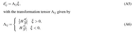
which provides the directions in which the transformation strains develop.Here,

In the above,ρais the density of the NiTi wires,the difference of the entropy at the reference state,Y the threshold value of transformationprovides the isotropic hardening term characterized by theThe above criterion is valid for both reverse and forward transformation but with different values of the parametersY,b1which accounts for the hysteresis of shape memory alloys.During cooling we have

The heat equation for for the NiTi wire is

where Cv= ρacais the heat capacity,kathe thermal conductivity,ρethe electrical resistivity and J the magnitude of the current density,
3.The constitutive law for auxetic material are
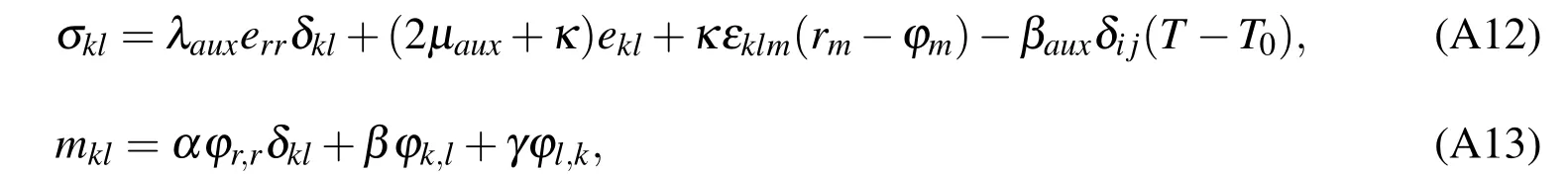
in which σklis the stress tensor(which is a symmetric tensor in classical elasticity but is asymmetric here),mklis the couple stress tensor(or moment per unit area),ekl=()is the small strain tensor(macrostrain vector),u is the displacement vector,and=1,and all other εklm=0)is the permutation symbol.The microrotation vector ϕkin Cosserat elasticity is kinematically distinct from the macrorotation vector rk=The quantitiesrefers to the rotation of points themselves,while rkrefers to the rotation associated with movement of nearby points.Here2µaux)αaux,with αauxthe coefficient of linear thermal expansions.
There are six independent elastic constants required to describe the auxetic material:Lamé elastic constants λaux,and µaux,Cosserat rotation modulus κ and the Cosserat rotation gradient moduli α,β,γ.For α = β = γ= κ =0 eqns(A4)and(A5)reduce to the constitutive equations of classical isotropic linear elasticity theory
The heat equation for the auxetic material

whereCaux=ρauxcauxis the heat capacity,kauxthe thermal conductivity.
The basic topological profile of the auxetic skin is presented in Figure 2.In the leftfigure,the hexagonal pores of the auxetic skin are presented together with the ZnO nanowires(red circles)positioned in the center of the hexagon).The 3D vertical array of nanowires is viewed in the yellow square at the right figure.
The 3D array of ZnO nanowires is viewed in the yellow square in the right figure.Each ZnO nanowire experiences axial strain when subjected to external mechanical deformation,with piezopotential induced inside the wire as a result of polarization of nonmobile ions distributed at the two ends[Wang(2012,2013);Zhang et al.(2011)].
Since a nanopiezotronic transistor involves a semiconductor that is piezoelectric,the fundamental governing equations for both semiconductor and piezoelectric theories are required.The basic equations for piezotronics are electrostatic equations,current–density equations,and continuity equations,which describe the static and dynamic transport behavior of the charge carriers in semiconductors,as well as the piezoelectric equations,which describe the piezoelectric behavior of the material under dynamic strains.The Poisson equation is the basic equation for describing the electrostatic behavior of charges[Wang(2012)]

where ψiis the electric potential distribution and ρ (r)is the charge density distribution,εsis the permittivity of the material.The current–density equations that correlate the local fields,charge densities and local currents are

where Jnand Jpare the electron and hole current densities,q is the absolute value of unit electronic charge,µnand µpare electron and hole mobilities,n and p are concentrations of free electrons and free holes,Dnand Dpare diffusion coefficients for electrons and holes,respectively,E is the electric field,and Jcondis the total current density.
The charge transport under the driving of a field is described by the continuity equations

where Gnand Gpare the electron and hole generation rates,Unand Upare the recombination rates,respectively.The piezoelectric behavior of the material is described by a polarization vector P.For a small uniform mechanical strain εk,the polarization vector P is given in terms of strain as

where the third order tensor eijkis the piezoelectric tensor.According to the conventional theory of piezoelectric and elasticity,the constituting equations can be written as

where σ is the stress tensor,E is the electric field,D is the electric displacement,cEis the elasticity tensor,and k is the dielectric tensor.
Consider the case of metal-wurtzite semiconductor contact,such as Au–ZnO or Ag–ZnO.For the ZnO the elasticity tensor is given by

the piezoelectric tensor nanowire along the c-axis(the direction of the growth of nanowires)the piezocoefficient matrix is

4.Boundary conditions
Boundary conditions do not depend on assumed material symmetry.We can prescribe the displacements uior the surface traction t(n)kand the microrotations ϕk,or the surface couples m(n)kon the surface which has exterior normal nl

The conditions on the interfaces between aluminum-NiTi wires,aluminum-auxetic material,NiTi wires-auxetic material are written as

with F0the total force acting by the finger on the interface
The boundary conditions for the finger are

The laws of motion also are independent of material symmetry. For the case without body forces and body couples,these equations are given by

Alderson,K.L.;Alderson,A.;Evans,K.E.(1997):The interpretation of strain dependent Poisson’s ratio in auxetic polyethylene. J.Strain Anal.,vol.32,pp.201-212.
Asano,A.;Saiki,M.;Fujio,M.(2009):Texture analysis based on mathematical morphology and MDL principle.Int.Workshop on Smart Info-media Systems in Asia(SISA2009),pp.155-159,October 22-23.
Bardinet,E.;Cohen,L.D.;Ayache,N.(1995):Analyzing the deformation of the left ventricle of the heart with a parametric deformable model.in Proceedings Conferenceon Computer Vision,Virtual Reality and Robotics in Medecine(CVRMed),Nice,France.
Baughman,H.;Shacklette,J.M.;Zakhidov,A.A.;Stafstrom,S.(1998):Negative Poisson’s ratios as a common feature of cubic metals.Nature,vol.392,pp.362-365.
Bezazi,A.;Scarpa,F.(2007):Mechanical behaviour of conventional and negative Poisson’s ratio thermoplastic polyurethane foams under compressive cyclic loading.International Journal of Fatique,vol.29,pp.922–930.
Bhattcharya,A.;Lagoudas,D.C.;Wang,Yand,Kinra,V.K.(1995):On the role of thermoelectric heat transfer in the design of SMA actuators;theoretical modeling and experiment.Smart Materials and Structures,vol.4,pp.252-263.
Bonnet,M.(1993):Shape identification problems using boundary elements and shape differentiation.Proc.of the 2-nd National Conf.on Boundary and Finite Element,ELFIN2,Sibiu,pp.35-48.
Boyd,J.G.;Lagoudas,D.C.(1994):Thermomechanical response of shape memory composites.J.Intell.Mater.Struct.,vol.5,pp.336-346.
Brocca,M.;Brinson,L.C.;Bazzant,Z.P.(2002):Three-dimensional constitutive model for shape memory alloys based on microplane model.Journal of the Mechanics and Physics of Solids,vol.50,pp.1051–1077.
Chan,N.;Evans,K.E.(1997):Fabrication methods for auxetic foams.Journal of Materials Science,vol.32,pp.5725–5736.
Chang,M.;Chou,Y.C.;Lin,P.T.;Gabayno,J.L.(2014):Fast and high resolution optical inspection system for in-line detection and labeling of surface defects.CMC:Computers,Materials&Continua,vol.42,no.2,pp.125-140.
Chen,K.T.;Huang,S.D.;Chien,Y.H.;Chang,W.C.;Lee,C.K.(2012):Development of an optically modulated piezoelectric sensor/actuator based on titanium oxide phthalocyanine thin film.Smart Materials and Structures,vol.21,no.11,115025.
Chiroiu,V.;Ionescu,M.F.;Sireteanu,T.;Ioan,R.;Munteanu,L.(2015):On intrinsic time measure in the modeling of cyclic behavior of a Nitinol cubic block.Smart Materials and Structures,vol.24,no.3,035022.
Chiroiu,V.;Munteanu,L.(2003):A flexible beam actuated by a shape memory alloy ribbon.Proc.of the Romanian Academy,Series A:Mathematics,Physics,Technical Sciences,Information Science,vol.4,no.1.
Chiroiu,V.;Munteanu,L.;Nicolescu,C.M.(2003):A shape description model by using sensor data from touch.Fourth Symposium on Multibody Dynamics and Vibration at the Nineteenth Biennial Conference on Mechanical Vibration and Noise ASME International Design Engineering Technical Conf.Chicago,sept 2–6,paper nr.DETC2003/VIB-48337.
Cosserat,E.(1909):Theorie des Corps Deformables.,Hermann et Fils,Paris.
Couprie,C.;Bresson,X.;Najman,L.;Talbot,H.;Grady,L.(2011):Surface Reconstruction using power watershed,pp.381-392.In:P.Soille,M.Pesaresi,G.G.Ouzounis(Eds.)Mathematical morphology and its applications to image and signal processing,10thInternational Symposium ISMM 2011,Verbania-Intra Italy,Springer.
Dahiya,R.S.;Valle,M.(2013):Robotic Tactile Sensing,Technologies and System.Springer.
Eringen,A.C.;Suhubi,E.S.(1964):Nonlinear Theory of Simple Microelastic Solids.part I-Int.J.Eng.Sci.2,pp.189-203,part II-Int.J.Eng.Sci.,vol.2,pp.389-404.
Eringen,A.C.(1966a):Theory of micropolar fluids,J.Math.Mech.,vol.16,pp.1-18.
Eringen,A.C.(1966b):Linear Theory of Micropolar Elasticity.J.Math.&Mech.,vol.15,pp.909-924.
Eringen,A.C.(1968):Theory of micropolar elasticity.In Fracture(ed.R.Liebowitz),Academic Press,vol.2,pp.621-729.
Ernst,M.O.;Banks,M.S.(2002):Humans integrate visual and haptic information in a statistically optimal fashion.Nature,vol.415,pp.429–433.
Escoffier,C.;Rigal,J.;Rochefort,A.;Vasselet,R.;Leveque,J.L.;Agache,P.G.(1989):Age-related mechanical properties of human skin-an in vivo study.J.Invest.Dermatol.,vol.93,pp.353–357.
Fearing,R.S.(1990):Tactile sensing mechanisms.Int.J.Robot.Res.,vol.9,no.3,pp.3–23.
Fujiki,A.;Asano,A.;Muneyasu,M.(2006):Unsupervised optimization of morphological filters for noise removal in texture images.Proc.Joint 3rd International Conference on Soft Computing and Intelligent Systems and 7th International Symposium on advanced Intelligent Systems,pp.1794-1799.
Gauthier,R.D.(1982):Experimental investigations on micropolar media,pp.395-463,in:Mechanics of Micropolar Media,CISM Courses and lectures,edited by O.Brulin and R.K.T.Hsieh,World Scientific
Goodwin,A.W.;Macefield,V.G.;Bisley,J.W.(1997):Encoding of object curvature by tactile afferents from human fingers.J.Neurophysiol.,vol.78,no.6,pp.2881–2888.
Johnson,K.L.(1985):Contact Mechanics.Cambridge University Press,Cambridge
Ju,W.E.;Moon,Y.J.;Park,C.H.;Choi,S.T.(2014):A flexible tactile feedback touch screen using transparent ferroelectric polymer film vibrators.Smart Materials and Structures,vol.23,no.7,074004.
Karnopp,D.(1985):Computer simulation of stick-slip friction in mechanical dynamic systems.Journal of Dynamic Systems,Measurement,and Control,vol.107,pp.100–103.
Lakes,R.S.;Benedict,R.L.(1982):Noncentrosymmetry in micropolar elasticity.Int.J.Engng.Sci.,vol.20,no.10,pp.1161-1167.
Lakes,R.S.(2001):Elastic and viscoelastic behaviour of chiral materials.Int.J.of Mechanical Sciences,vol.43,pp.1579-1589.
Lakes,R.S.(1986):Experimental microielasticity of two porous solids.Int.J.of Solids and Structures,vol.22,no.1,pp.55-63.
Liu,Y.;Davidson,R.;Taylor,P.(2005):Touch sensitive electrorheological fluid based tactile display.Smart Materials and Structures,vol.14,no.6,pp.1563-1568.
Love,A.(1944):A Treatise on the Mathematical Theory of Elasticity.Dover Publications,New York.
Marin Marin;Agarwal,Ravi,P.;Othman,M.(2014):Localization in time of solutions for thermoelastic micropolar materials with voids.CMC:Computers,Materials&Continua,vol.40,no.1,pp.35-48.
Mindlin,R.D.(1964):Microstructure in linear elasticity.Arch.Rat.Mech.Anal.,vol.16,pp.51-78.
Mindlin,R.D.(1965):Stress functions for a Cosserat continuum.Int J.Solids Structures,vol.1,pp.265-271.
Munteanu,L.;Chiroiu,V.;Bri¸san,C.;Dumitriu,D.;Sireteanu,T.;Petre,S.(2015):On the 3D normal tire/off-road vibro-contact problem with friction.Mechanical Systems and Signal Processing,vol.54-55,pp.377-393.
Munteanu,L.;Chiroiu,V.;Serban,V.(2014):From geometric transformations to auxetic materials.CMC:Computers,Materials&Continua,42(3):175-203.
Munteanu,L.;Bri¸san,C.;Donescu St.;Chiroiu,V.(2012):On the compression viewed as a geometric transformation.CMC:Computers,Materials&Continua,vol.31,no.2,pp.127–146.
Munteanu,L.;Chiroiu,V.;Dumitriu,D.;Beldiman,M.(2008):On the characterization of auxetic composites.Proceedings of the Romanian Academy,Series A:Mathematics,Physics,Technical Sciences,Information Science,vol.9,no.1,pp.33-40.
Otsuka,K.;Wayman,C.M.(1998):Shape Memory Materials.Cambridge Univ.Press,Cambridge.
Shu,S.G.;Lagoudas,D.C.;Hughes,D.;Wen.J.T.(1997):Modeling of a flexible beam actuated by shape memory alloy wires.Smart Materials and Structures,vol.6,pp.265–277.
Rediniotis,O.K.;Lagoudas,D.C.;Jun,H.Y.;Allen,R.D.(2002):Fuel-Powered Compact SMA Actuator.Proceedings of SPIE–The International Society for Optical Engineering,vol.4698,441.
Rucci,M.;Bajcsy,R.(1995):Learning visuo-tactile coordination in robotic systems.In:IEEE International Conference on Robotics and Automation,pp.2678-2683.
Scarpa,F.;Pastorino,P.;Garelli,A.;Patsias,S.;Ruzzene,M.(2004):Auxetic compliant flexible PU foams:static and dynamic properties.Physica Status Solidi B,vol.242,no.3,pp.681–694.
Schiffman,H.R.(2001):Sensation and Perception-An Integrated Approach.Wiley,New York
Sederberg,T.W.;Parry,S.R.(1986):Free-form deformation of solid geometric models.Proceedings of the 13thannual Conference on Computer graphics and interactive technologies,Newsletter ACM SIGGRAPH Computer Graphics,vol.20,no.4,pp.151-160.
Shikida,M.;Shimizu,T.;Sato,K.;Itoigawa,K.(2003):Active tactile sensor for detecting contact force and hardness of an object.Sens.Actuators A,Phys.vol.103,pp.213–218.
Wang,Z.L.(2010):Piezopotential gated nanowire devices:Piezotronics and piezo-phototronics.Nano Today,vol.5,pp.540-552.
Wang,Z.L.(2012a):Piezotronics and Piezo-Phototronics Springer-Verlag Berlin Heidelberg.
Wang,Z.L.(2012b):Progress in piesotronics and piezo-phototronics.Adv.Mater.,vol.24,no.34,pp.4632-4646.
Wang,Z.L.(2013):Piezotronics and Piezo-Phototronics.Springer,New York.
Weinberg,B.;Nikitczuk,J.;Fisch,A.;Mavroidis,C.(2005):Development of electro-rheological fluidic resistive actuators for haptic vehicular instrument controls.Smart Materials and Structures,vol.14,pp.1107–1119.
Wu,W.;Wen,X.;Wang,Z.L.(2013):Taxel-addressable matrix of verticalnanowire piezotronic transisyors for active and adaptive tactile imaging.Science,vol.340.
Wu,W.Z.;Wei,Y.G.;Wang,Z.L.(2010):Strain-gated piezotronic logic nanodevices.Adv.Mater.,vol.22,no.42,pp.4711-4715.
Zhou,J.;Fei,P.;Gu,Y.;Mai,W.;Gao,Y.;Yang,R.;Bao,G.;Wang,Z.L.(2008):Piezoelectric-Potential-Controlled Polarity-Reversible Schottky Diodes and Switches of ZnO Wires.Nano Lett.vol.8,no.11,pp.3973-3977.
Zhang,Y.;Liu,Y.;Wang,Z.L.(2011):Fundamental theory of piezotronics.Adv.Mater.,vol.23,no.27,pp.3004-3013.
1Institute of Solid Mechanics,Romanian Academy,Ctin Mille 15,010141Bucharest,Romania.
E-mails:ligia_munteanu@hotmail.com;dumitri04@yahoo.com;veturiachiroiu@yahoo.com;marin_doina@yahoo.com
2Technical University of Cluj-Napoca,Memorandumului 28,400114 Cluj-Napoca,Romania.
E-mails:Cornel.Brisan@mmfm.utcluj.ro;bmvbara@yahoo.com
