Three-Stages Magnetic Field Repeater for Extending the Range of Inductive Power Transfer
2015-11-16
(1.Department of Electrical and Computer Engineering,The University of Auckland Auckland 1142 New Zealand 2.College of Automation,Chongqing University Chongqing 400044 China)
1 Introduction
Inductive power transfer(IPT)is one of the most popular wireless power transfer technologies.It is based on magnetic resonance and near field coupling,which was first reported by Tesla in 1880[1],and now has gained many successful applications in materials handling,consumer electronics,and biomedical systems[2,3].
However,the near field coupling decreases very quickly with the increase of the physical distances between the power transmitting coil and power receiving coil.It is reported that 60 W of power can be transferred across 2 m,but the maximum power transfer efficiency was only 40% due to a reduced magnetic field coupling[4].As magnetic field repeaters can extend power transfer distances without sacrificing too much on the maximum power transfer capability and the power transfer efficiency,they offer an effective solution for extending the power transfer distance[5].
Among different types of magnetic field repeaters,rotary magnetic field repeaters are special in extending the power transfer range along a rotating shaft when direct wire connection is not convenient or impossible.This paper presents a power extension system with a 3-stage IPT repeater which supplies power to a biomedical device located at the end of a rotatable shaft of about 15cm away.The system is modelled and analysed to study the relationship between the reflected impedance and the system resonant operating frequency.A suitable 2nd order tuning method is proposed to investigate the characteristics of both parallel and series tuning power repeater coils,and practical experiments are undertaken to evaluate the system performance.
2 Proposed power extension system
The proposed power extension system is shown in Fig.1.It includes a DC-AC inverter,a 3-stage repeater formed by two middle stage magnetic field couplers,and a power receiver to drive an electrical load in the end.The system operates at a resonant frequency of about 290 kHz,so both the physical dimension and distance of interest is much shorter than the wavelength at this frequency(1 km),therefore the system belongs to near field inductive magnetic field coupling.

Fig.1 The overview system diagram
The proposed system receives power from an external dc source.A DC-AC inverter is designed for supplying a high frequency AC current to the resonant circuit of the transmitter.The AC current will generate a magnetic field around the transmitter coil.Repeater 1 will receive power from this magnetic field and relay power onto repeater 2,which further relays the power to the receiver circuit.The receiver then drives the load,which is a high power LED rated at about 5W in our example biomedical application.For power repeaters,second order compensation methods such as series tuning and parallel tuning can be used to maintain the circuit resonance and increase the power transfer capability.A voltage rectifier can be designed to invert the AC power to DC to drive the LED load.
3 System modelling and analysis
In the proposed system,the distances between the coupled coils are about 5 mm,which leads to a strong magnetic field coupling.As an autonomous inverter is used,which will be detailed in section 4,the soft switching resonant frequency of the proposed power extension system varies with the load due to the reflected impendences[6].To study the effects of the load on the resonant frequencies,the proposed power extension system can be modelled and fully analysed using the following equation[6]:

where ZSis the total equivalent impendence of the pick-up circuit; ω is the angular operating frequency of the system; and M is the mutual inductance between coils.
Based on Equ.(1),power extension systems with series tuned and parallel tuned repeaters can be analysed and compared.All the resonant circuits are assumed to be tuned at a nominal operating frequency of 290 kHz.Fig.2 and Fig.3 show the equivalent circuit diagrams of the systems with series tuned and parallel tuned repeaters respectively.
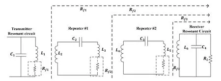
Fig.2 Series tuned repeater
Under the fully series tuned condition,L6is tuned with C4,L4and L5with C3,and L2and L3with C2,the system can be simplified to a current source at the output due to the impedance cancellation between inductor and capacitor.The reflected impedance is calculated at each stage using Equ.(1),and the reflected impendence Rf1is found to be a pure resistive load.In this case,in principle the reflected impedance in the transmitter coil will have no effect on the system resonant frequency.
For a system with parallel tuned power repeaters,after examining the reflected impedance at each stage,it can be found that the reflected impendence Zf1at the transmitter contains both the resistive part and the reactive part.
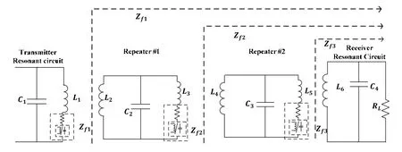
Fig.3 Parallel tuned repeater
The presence of this reflected impedance changes the equivalent resistance and reactance of the transmitter resonant circuit,which also changes the circuit quality factor Q based on the following definitions

where R is the reflected resistance,ωL is the total equivalent reactance including the reactive part of the reflected impendence.
If the harmonic component of the front stage inverter is ignored,the operating frequency of the system would also change with Q based on the following approximate equation[6]

where f0is the nominal undamped resonant frequency.From Equ.(1)~Equ.(3),the relationship between the operating resonant frequency and the load were calculated using MATLAB for both the series tuned and parallel tuned repeaters,and they are shown in Fig.4.

Fig.4 The relationship between the resonant frequency and output resistance
Fig.4(a) shows that the maximum resonant frequency of the system with series tuned repeaters is 290 kHz.The resonant frequency change variation is around 100 kHz for the load change from 3 Ω to 100 Ω,and it becomes approximately constant when the load resistance is larger than 25 Ω.For the parallel tuned repeater,the resonant frequency starts from 290 kHz and it only increases by approximately 32.5 kHz from 3 Ω to 100 Ω.
4 Practical system design
All parts of the proposed power extension system were fully designed,including the current-fed pushpull inverter,the power repeaters,and the power receiver for both the series tuned repeaters and parallel tuned repeaters.All component values were determined based on careful modelling and analysis of the system.
The current-fed push-pull autonomous inverter is designed and implemented with full ZVS switching without any external control circuitry.This makes the push-pull autonomous inverter very low in switching losses EMI compared to a fixed frequency PWM counterpart.Such an autonomous inverter can operate at a high frequency,and there is no common ground gate drive problems[7].
The repeater design aims to transfer 5 watts of power with a high efficiency.Both series tuning and parallel tuning were investigated.The nominal operating frequency of the developed 3-stages repeater was chosen to be 290 kHz.The coupling coefficients between coils were designed to be approximately 0.5.The schematic diagrams for the series tuned and parallel tuned circuits are shown in Fig.2 and Fig.3 respectively.Based on the theoretical calculations and practical measurements,the compensation capacitances were determined.Details of the component values are shown in Tab.1.
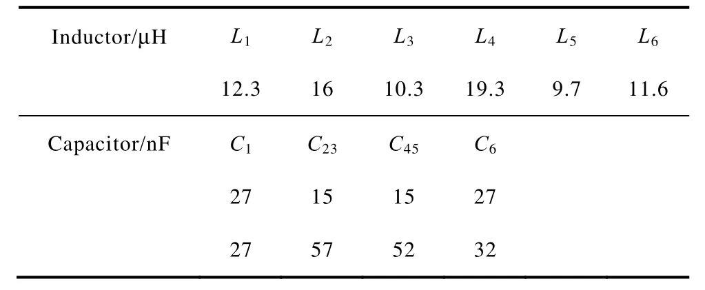
Tab.1 The inductor values and capacitor values of practical design
The receiver circuit was series tuned to provide a voltage source to the load under a fully tuned condition.In this case,the open circuit at load side will be safe at the output even the load is disconnected.In order to drive the DC load,a full-bridge rectifier was designed to convert the output AC power to DC.
5 Experimental results
A practical prototype power repeater system has been built and tested.The equipment output resistance of the LED load is 5 Ω at 5 V.All experimental component values are shown in Tab.1.The practical experimental set-up is shown in Fig.5.

Fig.5 The experimental setup of a 3-stages repeaters system
Fig.5 shows a DC to AC push-pull inverter is connected to the 3-stage repeater to extend the power transfer range along a shaft to a combined range of 15cm.The 3-stage repeater is connected to a load resistor through a voltage rectifier.The output voltage waveform for both the series tuned and parallel tuned repeaters are shown in Fig.6.
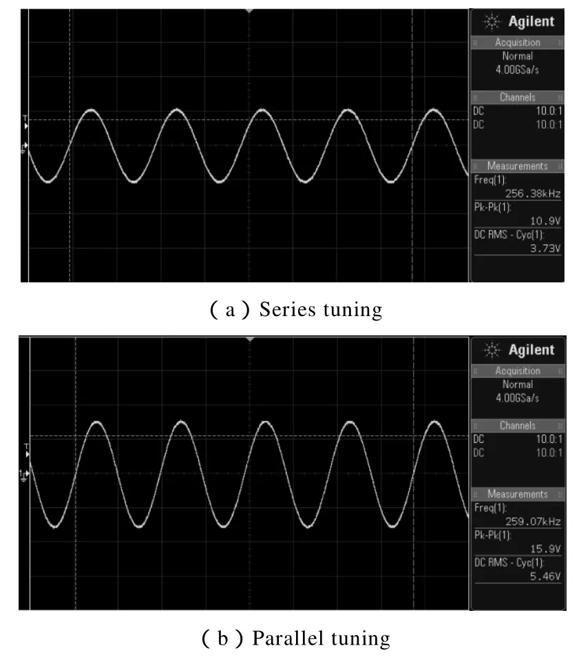
Fig.6 AC power output voltage waveform
Without the voltage rectifier,it is found that the system with series tuned repeaters operated at 256 kHz at an output voltage of 3.73 V.The output power was 2.78 W at a power transfer efficiency of 55%.For the system with parallel tuned repeaters,it is found that the resonant operating frequency was 259 kHz and the output voltage 5.46 V.The power at the output load was 5.98 W at a power transfer efficiency of 85%.
After adding the full bridge rectifier,the output power was tested with different DC load resistances using a DC electronic load.50 different output resistances were tested from 0~100 Ω in order to find the output characteristics of the power extension system.The experimental results for both the output power and power efficiency are shown in Fig.7.

Fig.7 The DC power transfer capability and efficiency testing results
Fig.7 shows that the system with parallel tuned repeaters transferred around 5 watts more power than the system with series tuned repeaters at the same loading resistance.The maximum power transfer of the parallel tuned repeater was around 8 W with a load resistance at approximately 10 Ω.The system with parallel tuned repeaters also had higher power transfer efficiency than the system with series tuned repeaters with same loads.The highest efficiency of the system with parallel tuned repeaters reached 72% with an approximatly 10 Ω output load resistor.
Compared to the system with series tuned repeaters,the system with a parallel tuned repeater had less frequency shifting.However,its modelling and analyses is more complex.It turned out that the system with parallel tuned repeaters performed better than its series turned counterpart,and it can transfer more than 5W of power required for driving the LED load for the example biomedical application.
6 Conclusions
A 3-stage power extension system including a transmitter,2 mid-stage power repeaters,and a power receiver has been proposed for a rotary biomedical application.The system has been modelled for analysing the load effect on the resonant operating frequency variations.The experimental results has demonstrated that both the parallel and series tuned repeaters can extend the combined power transfer distance along a shaft to 15cm,however,it has found that the system with parallel tuned repeater has a better power transfer performance than the series tuned counterpart.The parallel tuned repeater system can transfer 6 W AC power at 85% power transfer efficiency,and 5 W of DC power at 72% power transfer efficiency after a diode rectifier.
This paper is financially supported by National Natural Science Foundation of China(51477020).
Reference
[1] Secor H W.Tesla apparatus and experiments—how to build both large and small Tesla and Oudin coils and how to carry on spectacular experiments with them[J].Practical Electrics,1921.
[2] Si P,Hu A P,Budgett D,et al.Stabilizing the operating frequency of a resonant converter for wireless power transfer to implantable biomedical sensors[J].in Proc.1st Int.Conf.Sensing Technology,2005,477-482.
[3] Chen L,Boys J,Covic G,Power management for multiple-pickup IPT systems in materials handling applications[J].
[4] Kurs A,Karalis A,Moffatt R,et al.Wireless power transfer via strongly coupled magnetic resonances[J]Science,2007,317:83-86.
[5] Lee C,Zhong W,Hui S.Recent progress in mid-range wireless power transfer[J].In Energy Conversion Congress and Exposition(ECCE),2012 IEEE,2012:3819-3824.
[6] Hu A P.Selected resonant converters for IPT power supplies[J].ResearchSpace@ Auckland,2001.
[7] Abdolkhani A Hu A P.Improved autonomous currentfed push-pull resonant inverter[J].IET Power Electronics,2014,7:2103-2110.