Analysis of contact stress on interference fitted surface of the train axle-bearing
2015-10-29QingsongCAOXiaobingGUOGuoliangXIONG
Qing-song CAO, Xiao-bing GUO, Guo-liang XIONG
(School of Mechanical and Electrical Engineering, East China Jiaotong University, Nanchang 330013, China)
Analysis of contact stress on interference fitted surface of the train axle-bearing
Qing-song CAO*, Xiao-bing GUO, Guo-liang XIONG
(SchoolofMechanicalandElectricalEngineering,EastChinaJiaotongUniversity,Nanchang330013,China)
During railway vehicle rolling, the interference fitted surfaces between axle and bearing are worn due to fretting. The contact stress is one of the most important factors influencing micro damage. In this paper, the finite element model of axle-bearing interference fitted surfaces was established by using the finite element software ABAQUS. The influence of interference fit tolerance and friction coefficient on the contact stress was investigated. The results show that the interference fit tolerance has an important effect on the contact stress. The contact stress will be increased with the increasing of interference fit tolerance. The maximum stress appears on the contact edge of the fitted surface and stress concentration phenomenon is observed. Meanwhile, the friction coefficient has negligible effect on the contact stress of the fitted surface.
Axle-bearing, Interference fitting surface, Contact stress
1 Introduction
The connection method of interference fit is widely used in many equipment to transmit torque and axial force. Although it has simple structure and high connection strength, the tiny sliding on the interference fitted surfaces will be produced under the vibration environment and alternative load. Some surface phenomenon will be caused by micro damage, such as surface wear, loose components and power loss [1]. The contact stress is one of the most important factors influencing micro damage, and the magnitude of stress and distribution cannot be easily measured. Therefore, the finite element analysis method is widely used. A complicated dynamic model of roller bearing is established by CAO to study the problem of surface damage and radial clearance [2]. The finite element software ANSYS has be used to establish wheel-shaft structure model by Dongmei ZHAO, and the extended lagrange multiplier method is adopted to analysis nonlinear contact stress of the wheel-shaft interference fitted surface [3].
With the improvement of train speed, safety accidents occurred frequently due to the micro damage problem of axle-bearing interference fitted surface. In this paper, the finite element model of axle-bearing interference fitted surfaces was established based on the finite element software ABAQUS. The influence of interference fit and friction coefficient on the contact stress were investigated, and the contact stress distribution on the interference fitted surface was revealed.
2 The geometric model
A geometric model is set up for CRH2 axle and bearing, as shown in Fig.1. The axle is a 2180 mm long hollow axle, and the diameter of hole is 60 mm. SKF-TBU tapered roller bearings were adopted, the diameters of ring and outer ring are 130 mm and 230 mm, respectively. The axle-bearing interference fitted is used in the pressed assembly connection way.

Fig.1 Geometry model of CRH2 axle-bearing fitting surface
3 The finite element model
Interference problem, a kind of contact problem, belongs to complex problems that the boundary conditions are highly nonlinear. Its characteristic is that some boundary condition cannot be given at the beginning of the calculation, but the results of calculation, the contact area between the two contact bodies and pressure distribution will change along with the external load [4]. It is important to establish the correct contact relationship between units in the finite element model, and some special skills need be used to make the contact force convergence.
This paper studied the contact stress of the matching surface. Because the roller bearing has negligible effect on the contact stress of the fitted surface, the bearing could be instead of sleeve. Fully considering the symmetry of the model in calculation, a 1/10 the size of the original contract sets model was established. Because the stress is mainly concentrated on the external surface of the axle and the internal stress is relatively small, a grid control is adopted to improve precision. In addition, the unit nodes of the axle-bearing contact surface is coincide to ensure the smooth progress of the contact algorithm. The finite element model was established by using 38 nodes hexahedron nonlinear C3D8I coordination model unit, as shown in Fig.2. The Fig.2(a) is an axle-bearing coordinate grid model, and Fig.2(b) is a 1/10 tightening nested mesh model. The whole finite element model was divided into 237842 units.
4 The finite element method
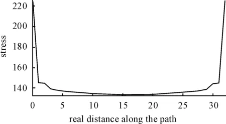
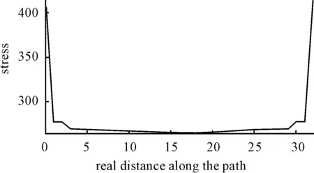
If the matching surface interference of the axle-bearing is not enough, the bearing inner ring will slid along the axle shaft direction, then the shaft neck surface will be damaged. If the interference is too big, the gaps and cracks are easy to be observed on the inner ring surface. According to the regulations of the emu CRH2 type four level maintenance procedures, the inner ring and shaft neck interference fit range is from 0.043 mm to 0.093 mm. Three models were established to analyze the characteristics of this system, in which the values of interference fit are 0.04 mm, 0.08 mm and 0.12 mm, respectively, and 0.12 mm is usually beyond the maximum allowed value. The axle and bearing elastic modulus is 2.1e11 MPa. Poisson’s ratio is 0.3, the friction coefficients are 0.2, 0.3 and 0.6, respectively. The relationships between the surface contact stress and interference were shown in Figs.3-5. The relationships between the surface contact stress and friction coefficient were shown in Figs.6-8. In Figs.3-8, horizontal axis is the real distance along the path, and vertical coordinate is the contact stress.
Fig.2 Finite element model of the axle-bearing interference fitted surface

Fig.3 Contact stress between the surfaces of axle-bearing (the value of interference is 0.04 mm)

Fig.4 Contact stress between the surfaces of axle-bearing (the value of interference is 0.08 mm)

Fig.5 Contact stress of between the surfaces of axle-bearing (the value of interference is 0.12 mm)

Fig.6 Contact stress of between the surfaces of axle-bearing (friction coefficient is 0.2)

Fig.7 Contact stress between the surfaces of axle-bearing (friction coefficient is 0.3)

Fig.8 Contact stress between the surfaces of axle-bearing (friction coefficient is 0.6)
5 Results
According to the interference fit tolerance and the deformation coordination conditions of the axle-bearing before and after fitting, the relationships between the pressure and the amount of interference was given by Lame equation [5]:
(1)
Where,pis contact pressure,νis the interference fit tolerance,Eis the axle and bearing elastic modulus,ais the lining radius of the hollow shaft,bis the outer wall radius of hollow shaft,cis the outer ring radius of bearing. Lame equation shows the proportional relationships between the pressurepand the amount of interferenceνin the linear elastic range. The Figs.3-5 show that contact pressures get linearly increased with the increased amount of interference in the middle of the contact area, and it is consistent with the prediction of Lame equation. The contact stress is singularity on the edge of the contact, and the contact stress gets increased sharply with the increase of amount of interference. The greater the stress is, the concentration phenomenon is more obvious. When the value of interference is 0.04 mm, the maximum stress is 225.7 MPa. When the value of interference is 0.08 mm, the maximum stress is 300.2 MPa. When the value of interference is 0.12 mm, the maximum stress is 414.2 MPa.
During railway vehicle rolling, the initial friction coefficient of the contact area is affected by many factors, such as the matching surface roughness, different material and lubricant. In this paper, the friction coefficients are 0.2, 0.3, and 0.6, respectively. From Figs.6-8, it shows that the contact stress gets decreased with the increase of friction coefficients, however the change is relative small. The maximum contact stress is obtained at the edge of the contact surface, which are 211.2 MPa, 195.7 MPa and 192.7 MPa, respectively. The minimum value is obtained in the center of the contact area, which are 121.0MPa, 113.0 MPa, and 112.0 MPa, respectively. Therefore, the friction coefficient has almost no influence on the value of contact stress.
6 Conclusions
The coupling system interference fit surface of the train bearing inner ring and axle often arise micro damage, so the train safety is affected. The bearing-axle finite element model was established based on the CRH2 axle and bearing. The contact stress of the bearing inner ring and axle interference fit surface was exploratory studied. The results shown that the value of interference has an important effect on the contact stress. As the interference fit tolerance increasing, the contact stress will get increased. The maximum stress of the fitted surface on the contact edge and the stress concentration phenomenon will be observed. Therefore, the axle-bearing fitting surface fatigue damage could be easily caused. The contact stress is almost not effected by the friction coefficient. In practical application, the interference quantity deficiency can lead that cooperate is unreliable. Thus, the bearing inner ring will slid along the axle shaft direction. However, the fatigue crack will be produced when the value of interference fit is too big on the matching surface. Therefore, the suitable system interference tolerance of the train axle-bearing is selected to prevent micro damage, and to improve the service life.
Acknowledgement
This paper is supported by the National Natural Science Foundation of China (No.51265009, No. 51265010).
[1]Huang M N, Zeng F, Zhou Z R. Analysis and Countermeasure of Fretting Damage on Wheel/axle Interface[J]. Railway Locomotive & Car, 2010, 30(3): 21-24.
[2]Cao M, Xiao J. A Comprehensive Dynamic of Double-row Spherical Roller Bearing Model Development and Case Studies on Surface Defects, Preloads, and Radial Clearance[J]. Mechanical Systems and Signal Processing, 2008, 22(2): 467-489.
[3]Zhao D M. Contact Stress Analysis of Interference Fit of Axle and Wheel of the Vehicle[J]. Machinery, 2012, 12(39): 46-48.
[4]Zhang D P. Liu X P. A Nonlinear Contact Finite Element Analysis of Assembly Stress on Vehicle Axle Interference Fit[J]. Tibet’s Science and Technology, 2010(7): 78-80.
[5]Zhang Y, McClain B, Fang X D. Design of Interference Fits Via Finite Element Method[J]. Mechanical Sciences, 2000(9): 1835-1850.
10.3969/j.issn.1001-3881.2015.24.006 Document code: A
U266.2
列车车轴-轴承过盈配合面接触应力分析
曹青松*, 郭小兵, 熊国良
华东交通大学 机电工程学院, 南昌330013
在列车运行过程中,车轴-轴承过盈配合面将发生微动而造成微动损伤,接触应力是影响过盈配合面微动损伤的主要因素之一。以CRH2动车组的车轴和轴承为对象,利用有限元软件ABAQUS建立车轴-轴承过盈配合面的接触模型,研究了过盈量、摩擦系数对接触应力的影响。结果表明:过盈量对配合面接触压力的影响较大,接触应力随着过盈量的增加而增大,且在配合面接触边缘区域产生最大应力,存在应力集中现象;而摩擦系数对配合面接触应力的影响较小。
车轴-轴承;过盈配合面;接触应力
15 June 2015; revised 20 September 2015;
Qing-song CAO, Ph.D.,
Associate professor. E-mail: 2000cqs@163.com
accepted 17 October 2015
Hydromechatronics Engineering
http://jdy.qks.cqut.edu.cn
E-mail: jdygcyw@126.com
猜你喜欢
杂志排行
机床与液压的其它文章
- Molecular dynamics study of the effects of tool geometric parameters on titanium nanometric cutting
- Research on active suspension control strategy based on fuzzy PID control
- The design of control system applied in artificial grass tufting machine adopting servomotors
- Co-simulation and consumption analysis of wheel loader on negative loading condition
- Influence of the underlap in the poppet valve on its performance
- Comprehensive reliability evaluation of foreign high-end gantry machining Center
