Illum ination M odel of M ixed W hite Light-em itting Diode System w ith Three-dimensional Conditions
2015-07-21CAIJiayiCHENHuantingZHOUXiaofangHUANGMalianZHOUJinrongHEZhongquan
CAI Jia-yi,CHEN Huan-ting,*,ZHOU Xiao-fang*, HUANG Ma-lian,ZHOU Jin-rong,HE Zhong-quan
(1.Department ofPhysics and Information Engineering,Minnan Normal University,Zhangzhou 363000,China; 2.Fushun Optoelectronics Science and Technology Co.,Ltd.,Zhangzhou 363000,China) *Corresponding Authors,E-mail:htchen23@163.com;zhou9190@vip.sina.com
Illum ination M odel of M ixed W hite Light-em itting Diode System w ith Three-dimensional Conditions
CAI Jia-yi1,CHEN Huan-ting1,2*,ZHOU Xiao-fang1*, HUANG Ma-lian1,ZHOU Jin-rong1,HE Zhong-quan2
(1.Department ofPhysics and Information Engineering,Minnan Normal University,Zhangzhou 363000,China; 2.Fushun Optoelectronics Science and Technology Co.,Ltd.,Zhangzhou 363000,China) *Corresponding Authors,E-mail:htchen23@163.com;zhou9190@vip.sina.com
A nonlinear approach of controlling the illumination of a mixed white LED system was proposed.This LED system ismade up of awarm color LED source and a cool color LED source.The overall illumination of the LED system is due to the combined emitted flux of both LED source.With reasonable approximation,the proposed theoreticalmodelswith three-dimensional conditions are simplified into practical solutions,which aim at providing a comprehensive LED system theorywith physicalexplanations for electronics engineers and researchersworking in LED system designs.The proposed model consists of simple process of optical and electricalmeasurements,which are easy for LED devicemanufactures and system designers to follow.The proposedmethod has been tested withmixed white LED system.The theoretical results are reasonably in good agreementwithmeasured values.The idea is applicable to LED system withmultiple sources and is not limited to white LEDs.
mixed white;light-emitting diode;illuminationmodel;three-dimensional(3D)conditions
1 Introduction
The light-emitting diode(LED)is considered an attractive candidate for replacing incandescent and fluorescent lightings for general energy-efficient illumination purpose.There are,however,various aspects that require attention when it comes to applying LEDs for general lighting.One such aspect is related to the LED's junction temperature,which critically affects its operating lifetime,luminous efficiency,illumination and color properties,and must be properly considered when it comes to designing good-quality light sources[1-4].In particular, there is about seventy percentof the input power into heatenergy,which will lead to a sharp rise of the LED's temperature[5].For this reason,most research works related to LED ballasts so far,have been focused on achieving high energy efficiency, good dimming properties,and high reliability through the avoidance of using electrolytic capacitors.For indoor lighting applications,it is important to take into account illumination of target surface.In particular,LED lamps based on warmwhite LED with lower CCT and cool-white LED with high CCT are a popular configuration.To perform dimming control of a mixed white LED lamp,the light intensity emitted by the individual LED should be adjusted.
Hu et al.[6]fabricated a new white LED by irradiating the mixed fluorescent powder which contained[Ru(dtb-bpy)3]2+(PF-6)2and YAG.Cao et al.[7]proposed different kinds of SiO2current blocking layer by plasma enhanced chemical vapor deposition(PECVD)and etched.Thermal-electrical-luminousmodel of a RGB LED system for lighting controlwas proposed[8],in which can accurately describe dynamic luminous behavior and be used as control of RGB LED systems.With the use of wallplug efficiency,it described the theoreticalmodel of LED systems,which have provided a framework for analyzing LED systems[9].Bender et al.[10]developed an illuminationmodel to relate junction temperature and injection current,providing an optimal operating point to achieve themaximum luminous flux. Huang et al.[11]derived the variation rule of LED junction temperature from a perspective of input power,in which the dynamic model of an LED system is further taken into account.
Wen et al.[12]presented an occupant-specific lighting system for open-plan office environments in which energy saving and illumination control were formulated as a linear problem.However,a drawback of this approach is that there is no guarantee that the proposed iterative algorithm would converge in finite time.Miki etal.[13]carried out regulation of the target illumination with reduction electrical power.Xiao etal.[14]proposed a rapid reliability evaluation method of LED lamp based on the acceleration degradation test.
The work in this paper is targeted to the use of illumination as a function of currentand 3D locations for controllingmixed white LED lamps.Themathematical model of total illumination of mixed white light LED system as a function of injection current, x axis,y axis,and height has been proposed.The required parameters of proposed model could be extracted based on a series of optical and electrical measurements.The proposed model could accurately predict illumination levels at any target points.Experimental results are used to validate the proposed method.
2 Characterization and Model of Illumination of An LED System with 3D Locations and Injection Current
2.1 Practical Illum ination vs.x or y Axis of Target Surface and Current
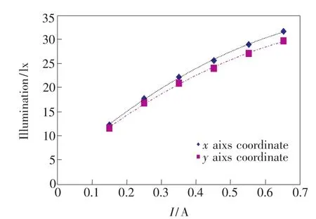
In practice,illumination of an LED system Ex/Eyis related to x/y axis coordinates and injection current.The relationship is reflected in the x/y axis coordinates and the illumination of white light LED with the constant current I1/I2as shown in Fig.1. These practicalmeasurements are obtained with the use of a spectral irradiance colorimeter(SPIC-200) that provides practicalmeasurements of illumination. In the practical operating range,the relationship of the illumination as a function of the x/y axis coordi-nate under constant injection current I1/I2is fairly quadratic and can be approximated as

whereα1,α2,β1,β2,μ1andμ2are the constants that can be extracted from Fig.1 with constant current.

Fig.1 Illumination vs.x/y axis coordinates under constant current
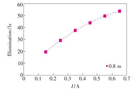
To establish the dependence of the Ex/Eyon the LED current,the LED system is operated with the current between 0.15 A and 0.65 A.The practical measurements of the Ex/Eyas a function of current I are obtained and shown at constant axis coordinates x1/y1in Fig.2.It is shown that the Ex/Eyincreases as the current.The illumination function is approximately a parabola and therefore has amaximum illumination at P*d.This P*dwill shift to lower value with an increasing heatsink's resistance or heat dissipation.It is indicated that the operating point of the LED systems are dependent on the junction temperature and injection current.Therefore,the Ex/Eycan be obtained as a quadratic polynomial function of injection current.

whereχ1,χ2,δ1,δ2,η1andη2are the constants that can be extracted from themeasurements in Fig.2.
Based on the aforementioned analysis,the Ex/Eycan be expressed in terms of current and x/y axis coordinates using a 2-D nonlinear function[15]. The nonlinear function of Ex/Eywith current along x/y axis is constructed in the following:


Fig.2 Illumination vs.currentunder constant x/y axis coordinates

Whereε1is the intersection value of functions of(1) and(3),which is the value of Exat point(x1,I1). Similarly,ε2is the intersection value of functions of (2)and(4),it is the value of Eyat point(y1,I2). Equation(5)and(6)link the illumination of the LED system Ex/Eyto current and x/y axis coordinates together.It should be noted that the proposed model can estimate the illumination of the LED system at any current and x/y axis coordinates.
2.2 Illum ination M odel for x and y Axis of Target Surface and Current
These coefficients of Equation(5)and(6)describe the illumination behavior with current and two-dimensional locations.It is shown that illumination is as a function of three variables(current,x axis coordinate and y axis coordinate),the behavior of the illumination of the LED system E(x,y,I)is given by 2-D nonlinear function,as shown in(7), whereε3is the intersection value of E at point axis coordinate(0,0).It is an equation that combines the current,x axis coordinate,and y axis coordinate aspects of an LED lighting system.

2.3 Illum ination vs.Current and Height
The illumination of the LED system Ehis highly related to height.To establish the dependence of Ehon the height,the LED system is operated in the height from 0.6 to 1.0 m.Generally,Ehobviously decreases as the height increasing.Themathematical description of the illumination behavior as quadratic function on the height is indicated in Fig.3,as shown in the following:

whereα3,β3andμ3are achieved by curve fitting in Fig.3.

Fig.3 Illumination vs.height under constant current
The relationship is expressed as the current and the illumination of the LED system with the constant height h1as shown in Fig.4.The illumination is dependent on the current should be represented as

whereχ3,δ3andη3are achieved by curve fitting in Fig.4.
According to the above analysis process,the illumination of the LED system Ehcan be represented in terms of current and height.Therefore,the expression of Ehis given by:


Fig.4 Illumination vs.current under constant height
Whereε4is the intersection value of functions of(8) and(9),which is the value of Ehat point(h1, I3).Equation(10)links the illumination of the LED system Ehon origin position to current and height together.
2.4 Illum ination M odel of LED System w ith Current and 3D Locations(x,y Axis and Height)
Combined Equation(7)with(10),the illumination as a function of the LED system with 3D locations and injection current can be determined as

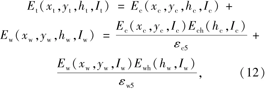
Therefore,the overall illumination of a mixed white LED system Et(xt,yt,ht,It)with a cool white LED and a warm white LED is shown as Equation(12):

Where Ec(xc,yc,hc,Ic)is individual illumination of the cool white LED and Ew(xw,yw,hw,Iw)is individual illumination of the warm white LED.
Several important observations should be noted from Equation(12):
(1)Equation(12)relates the illumination to the forward current I,the physical distance along x and y axis,the height altogether.It is an equation that integrates the electrical and physical distance of the LED system altogether.
(2)LED device manufactures can use injection current and 3D locations in Equation(12)to quantify the overall illumination of amixed white LED system. This new equation quantitatively sums up the relationship among illumination,current and 3D locations.
(3)If space for the heatsink is not an issue,a big heatsink with low thermal resistance should always be selected for the LED system in order to effectively reduce the reduction of the illumination at higher temperature.
3 Experiment and Verification for The Proposed Modeling
In the experiments,a cool white LED(CREE-XPE 3W)and awarm white LED(CREE-XPE 3W) making up the mixed white LED system are mounted on a heatsink.The ambient temperature is kept constant at 25℃and the heatsink operates under free convection with no active temperature control.
Opticalmeasurements are carried outafter driving the LED system for 10 min that steady-state thermal conditions have been reached.The illumination is measured at different currentand 3D locations.The required parameters for Equation(12)are shown in Table 1 and 2.

Table 1 Required coefficients for proposed model of cool white LED

Table 2 Required coefficients for proposed model of warm white LED
Based on these parameters,the theoretical Et(xt,yt,ht,It)can be determined,plotted,and compared with practicalmeasurements,as shown in Fig.5.Mea-1,-2,-3 can be defined as the measured illumination of the LED system with Iw=0.15 A,Ic=0.15 A;with Iw=0.25 A,Ic=0.25 A; with Iw=0.35 A,Ic=0.45 A,respectively.Cal-1, -2,-3 can be defined as the calculated illumination ofwhite LED lampswith Iw=0.15 A,Ic=0.15 A, εw3=10.02 lx,εw5=10.02 lx,εc3=12.96 lx,and εc5=12.96 lx;with Iw=0.25 A,Ic=0.25 A, εw3=15.34 lx,εw5=15.34 lx,εc3=18.32 lx,and εc5=18.32 lx;with Iw=0.35 A,Ic=0.45 A, εw3=19.14 lx,εw5=19.14 lx,εc3=27.26 lx,and εc5=27.26 lx,respectively.
The agreement between measured and calculated is reasonably good.The maximum relative error between measured and calculated results is 13.6%, theminimum relative error is about 7.6%,and the average relative error is about11.2%.

Fig.5 Illumination vs.3D location with different current
4 Conclusion
A nonlinear method of controlling illumination of the mixed white LED system with three-dimensional locations and current is proposed in this paper.The control is built upon nonlinear empirical illumination model of the LED system that are developed from the experimental results obtained in this work.The parameters obtained in required optical and electricalmeasurements can predict the illumi-nation of themixed white LED lamp thatmay not be easily accessed in practice.This approach is applicable to LED systems with multiple light sources. The estimation method presented in this paper enriches the LED lighting system theory by considering current and 3D locations.It is envisaged that the proposed method can be used as a design tool for LED system designs.
[1]Garcia J,Costa D M A,Secades M R.Dimming of high-brightness LEDs by means of luminous flux thermal estimation [J].IEEE Trans.Power Electron.,2009,24(4):1107-1114.
[2]Dyble M,Narendran N,Klein T.Impact of dimming white LEDs:Chromaticity shifts due to different dimming methods [J].SPIE,2005,5941:291-299.
[3]Chen H T,Lu Y J,Gao Y L,et al.The physical characteristic study on luminance uniformity and temperature for power GaN LEDs chip[J].Acta Phys.Sinica(物理学报),2012,61(16):167104-1-6(in Chinese).
[4]Ma JS,He L Y,Liu T,etal.Design of optical structure for chip-on-board wafer level packaging LEDs[J].Opt.Precision Eng.(光学精密工程),2013,21(4):904-910(in Chinese).
[5]Lei S J,Ma Q,Yin D K,et al.Heat dissipation of LED back lightunits based on TRIZ[J].Chin.J.Liq.Cryst.Disp. (液晶与显示),2012,27(1):56-60(in Chinese).
[6]Hu C Q,Zhang FH,Zhang J.The spectral and junction temperature properties of new white light LED[J].Chin.J.Lumin.(发光学报),2012,33(9):939-943(in Chinese).
[7]Cao W W,Zhu Y X,Guo W L,et al.Improving luminous efficacy of the GaN-based light-emitting diodes by using different shapes of current blocking layer[J].Chin.J.Lumin.(发光学报),2013,34(4):480-483(in Chinese).
[8]Huang B J,Tang CW.Thermal-electrical-luminousmodel ofmulti-chip polychromatic LED luminaire[J].Appl.Therm. Eng.,2009,29:3366-3373.
[9]Chen H T,Hui SY R.Dynamic prediction of correlated color temperature and color rendering index of phosphor-coated white light-emitting diodes[J].IEEE Trans.Ind.Electron.,2014,61(2):784-797.
[10]Bender V C,Iraonka O.Designmethodology for light-emitting diode systems by considering an electrothermalmodel[J]. IEEE Trans.Electron.Dev.,2013,60(11):3799-3806.
[11]Huang B J,Tang CW,Wu M S.System dynamicsmodel of high-power LED luminaire[J].Appl.Therm.Eng.,2009, 29(4):609-616.
[12]Wen Y J,Agogino A.Control of wireless-networked lighting in open-plan offices[J].Lighting Res.Technol.,2011,43 (2):235-248.
[13]MikiM,Hiroyasu T,Imazato K.Proposal for an intelligent lighting system and verification of controlmethod effectiveness [J].IEEE Xplore,2004,1:520-525.
[14]Xiao C D,Liu C J,Liu W D,etal.Reliability assessment of LED lamp based on acceleration degradation test[J].Chin. J.Lumin.(发光学报),2014,35(9):1143-1151(in Chinese).
[15]Chen H T,Tao X H,Hui SY R.Estimation of optical power and heat-dissipation coefficient for the photo-electro-thermal theory for LED system[J].IEEE Trans.Power Electron.,2012,27(4):2176-2183.

蔡嘉毅(1991-),男,福建漳州人,硕士研究生,2013年于闽南师范大学获得学士学位,主要从事光电材料及其计算方面的研究。
E-mail:1247549642@qq.com

陈焕庭(1982-),男,福建漳州人,博士,副教授,2010年于厦门大学获得博士学位,主要从事半导体光电子学方面的研究。
E-mail:htchen23@163.com
三维空间下混合白光LED系统照度模型
蔡嘉毅1,陈焕庭1,2*,周小方1*,黄马连1,周锦荣1,何仲全2
(1.闽南师范大学物理与信息工程学院,福建漳州 363000; 2.富顺光电科技股份有限公司,福建漳州 363000)
针对包含暖白光和冷白光两种不同LED光源的混合白光LED系统,提出一种非线性控制混合白光LED系统照度模型的方法论。该混合白光LED系统包含暖白光及冷白光两种不同LED光源。混合白光LED系统总照度取决于两个LED光源所占的光通量比例,据此提出三维空间下不同电流负载情况下的混合白光LED系统的照度模型,通过简单的光学及电学测试方法校准,并实验测试验证该三维照度模型的真实性。该方法对混合白光LED系统的应用具有一定参考价值,而且其适用于多个光源的LED系统,并不仅限于白光LED。
混合白光;发光二极管;照度模型;三维空间
2015-06-28;
2015-07-24
国家自然科学基金(61307059);福建省教育厅科研计划(JA13191,JK2014027);福建省区域重大专项(2014H4018)资助项目
O482.31 Document code:A
10.3788/fgxb20153609.1088
1000-7032(2015)09-1088-06
