Processing the rig test data of an air filling twin-tube shock absorber
2015-04-22DONGMingming董明明DONGMingming董明明LUOZhenxing骆振兴ZHAOYongfei赵永飞
DONG Ming-ming(董明明), DONG Ming-ming(董明明),LUO Zhen-xing(骆振兴), ZHAO Yong-fei(赵永飞)
(1.School of Mechanical Engineering, Beijing Institute of Technology, Beijing 100081, China;2.Changan Auto Global R & D Institute, Chongqing 401120, China)
Processing the rig test data of an air filling twin-tube shock absorber
DONG Ming-ming(董明明), DONG Ming-ming(董明明)2,LUO Zhen-xing(骆振兴)1, ZHAO Yong-fei(赵永飞)1
(1.School of Mechanical Engineering, Beijing Institute of Technology, Beijing 100081, China;2.Changan Auto Global R & D Institute, Chongqing 401120, China)
A separation method is proposed to design and improve shock absorber according to the characteristics of each force. The method is validated by rig test. The force data measured during rig test is the resultant force of damping force, rebound force produced by pressed air, and friction force. Different characters of damping force, air rebound force and friction force can be applied to seperate each force from others. A massive produced air filling shock absorber is adopted for the validation. The statistic test is used to get the displacement-force curves. The data are used as the input of separation calculation. Then the tests are carried out again to obtain the force data without air rebound force. The force without air rebound is compared to the data derived from the former tests with the separation method. The result shows that this method can separate the damping force and the air elastic force.
air filling shock absorber; force-stroke curve; rig test data; forces separation
Shock absorber performance is crucial to the vehicle suspension behaviors for handling and ride comfort[1]. Pressure air helps “twin-tube” damper with simple structure and high reliability to conquer the “filling defects by lack of oil” when working at high-frequency excitation[2].
Many sophisticated shock absorber models have been established for research on dynamic performance. Besinger et al.[3]and Mollica et al.[4], established a precise shock absorber dynamic model to analyze the nonlinear vibration characteristics. Simms et al.[5-6]studied dynamic behaviors by computer simulation and rig test. Herr et al.[7], introduced computational fluid dynamics (CFD) method to study the dynamic performance. Neural network approach was introduced by Fash J W[8]to work out accurate characteristics of the damper. Duym et al. and Cossalter[9-10]developed a physical model with hysteretic behavior. Lion et al.[11]developed a model to depict nonlinear force-velocity behavior characteristics. However, no study of forces separation analysis has been carried on for the difficulties of forces coupling. In this paper, a separation method is proposed for shock absorber design and improvement according to the characteristics of each force and is validated by rig test.
1 Model of shock absorber
The outer tube of air filling twin-tube shock absorber filled with pressure air which can accelerate the oil flow during restore stroke to improve the high speed performance and decrease the foaming, is widely used in modern cars. The air filling twin-tube shock absorber is shown in Fig.1. Fig.2 shows how the shock absorber is installed on the test rig. The upper end is connected with a fixed force sensor while the lower end with the test rig, whose displace is measured by the displacement sensor. All these data are collected by data acquisition card and inputted into computer.
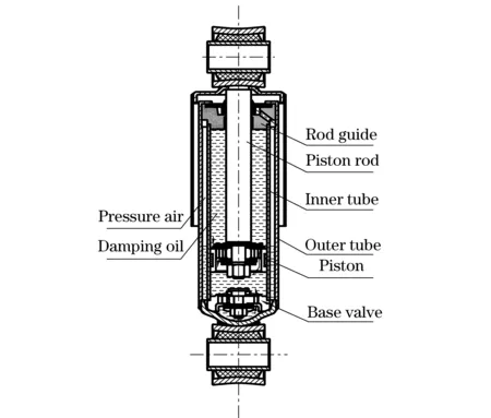
Fig.1 Sketch of air filling twin-tube shock absorber
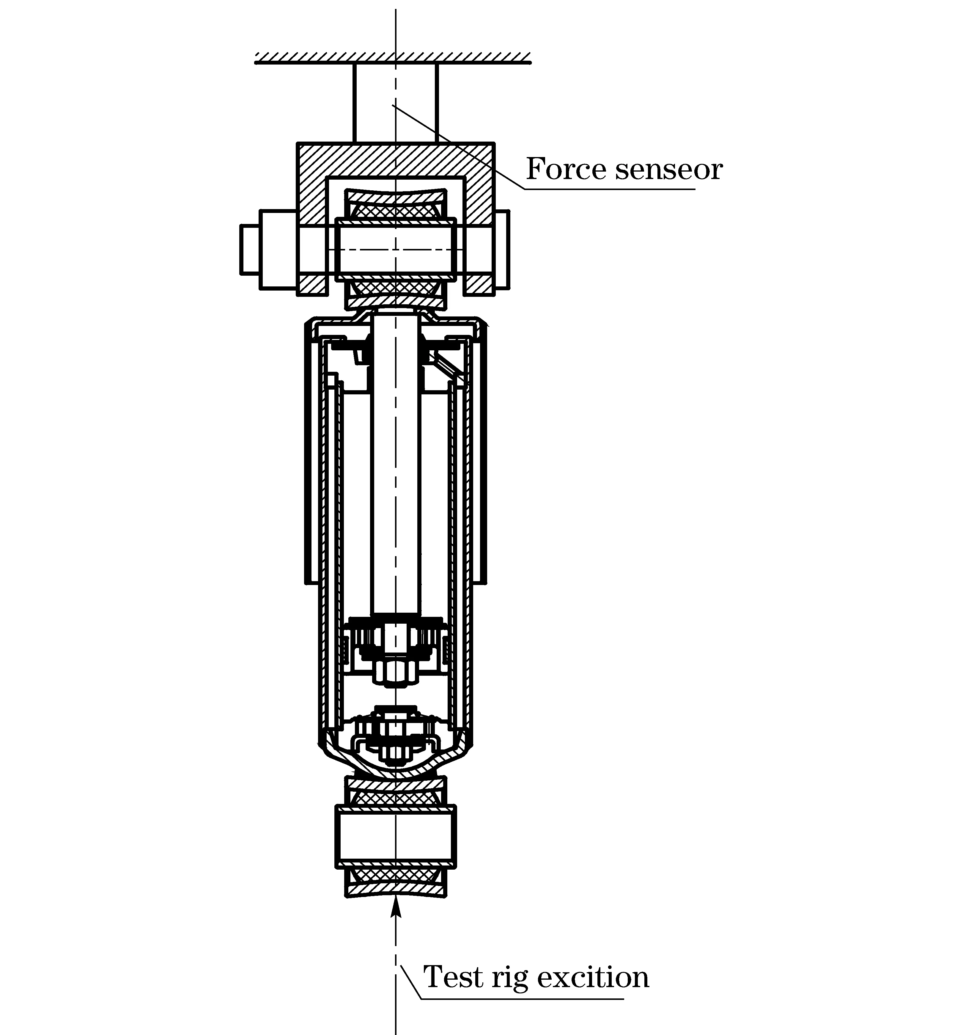
Fig.2 Sketch of installing shock absorber on test rig
From Fig.2, the output force of the force sensor is composed of three parts[12]:
Fa=Fc+Fg+Ff
(1)
whereFais the output force,Fcis hydraulic damping force,Fgis elastic force caused by pressure air,Ffis friction force between piston with inner tube and piston rod with seal in guide. The equivalent model can be expressed in Fig.3.
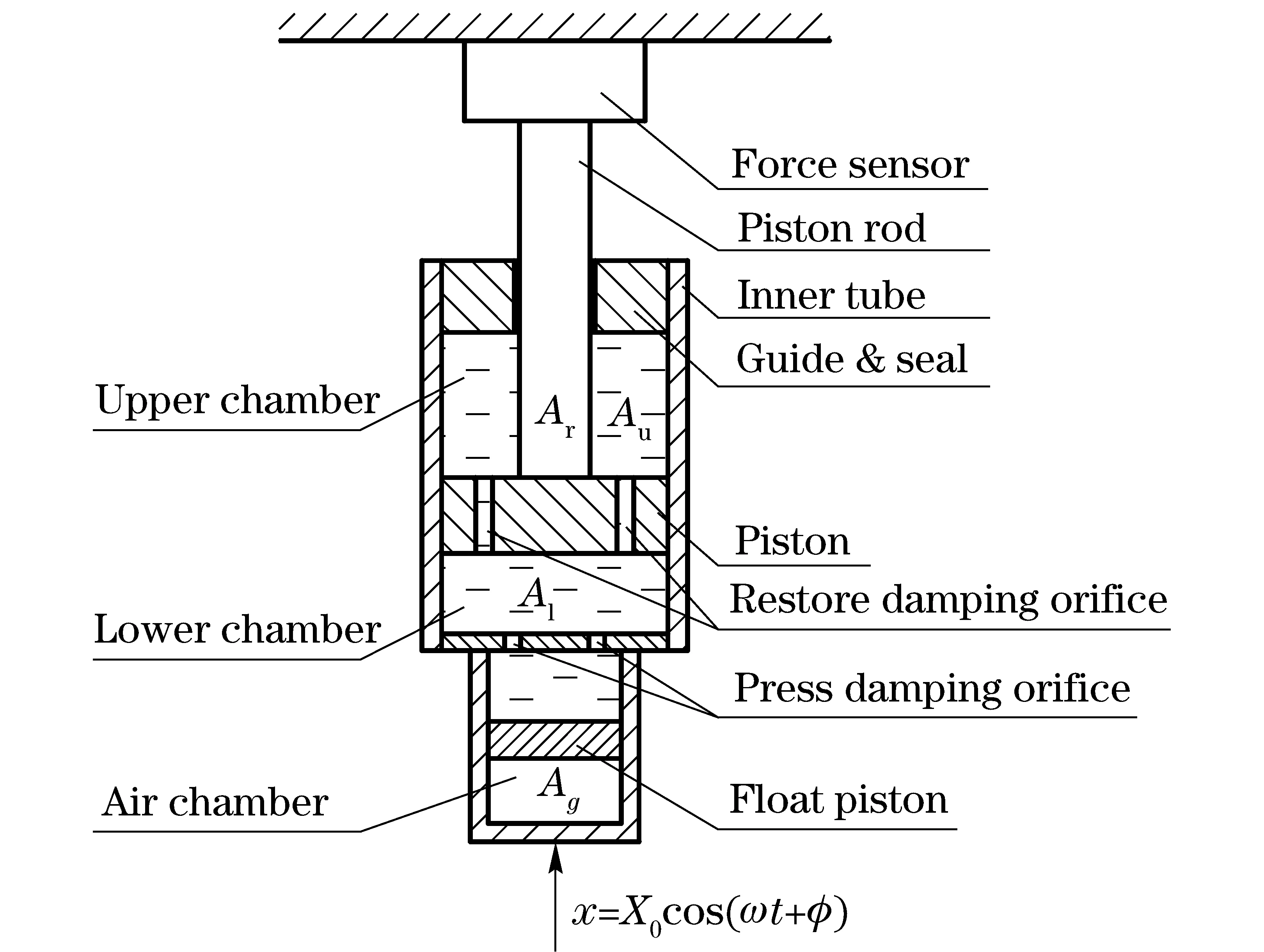
Fig.3 Equivalent model of shock absorber
2 Rig test of shock absorber
During the shock absorber performance test, the excitation is sinusoidal with amplitude of 50 mm. To achieved different test velocity, ordinary as: 0.16,0.32,0.52,0.64 m/s, different excitation frequencies are needed:
(2)


Fig.4 Shock absorber force-stroke curve
For ordinary damper, the damping force is proportional to the excitation speed on the lower end, and the restore stroke damping coefficient is larger than compress stroke, which makes the stroke-damping force curve consist of two semiellipses with the same major axis, as shown in Fig.4a. The air filling damper can be regarded as a damper and a gas spring in parallel. The displacement force curve is shown in Fig.4b (Pulling force is positive and compression force is negative).
3 Forces characteristics analysis
The force data are derived from the rig test, which is the sum of damping force, gas rebound force and friction force. To meet the realistic requirement, a high accurate calculation method to separate these three is in great need.
3.1 Air elastic force
Air elastic force can be expressed as
Fg=p(Al-Au)=pAr
(3)
whereAlis area of piston,Auis upper area of piston,Aris sectional area of piston rod,pis air pressure. Using the static equilibrium position as the origin ofx, the length of the gas column isx0. So the volume of the air is
V0=Atx0
(4)
whereAtis the sectional area of the air column. When the length of damper changesx(extension is positive), the air volume can be calcualted as
V=V0+Arx
(5)
For low pressure air (≤0.4 MPa) in the shock absorber, the ideal gas equation is introduced to calculate the pressure change.
(6)
whereγiisgaspolytropicexponent.Incommontestconditions,itisabout1.3.), pais standard atmospheric pressure, and p0is air pressure of static equilibrium position.
To enhance the accuracy of forces separation, the parameters except for polytropic exponent can be identified by statistic test in which the rebound force data is measured at different lengths of shock absorber statically so that the hydraulic force and friction is zero. With the rebound force values at different shock absorber lengths, the pressure can be calculated by isothermal process as
(p0+pa)V0=(p+pa)(V0+Arx)
(7)
The gas pressure can be calculated as
(8)
UsingtwovectorFiandxitoexpresstheforcedataanddisplacementdataofncomponents.ThepressurevectorpicanbecalculatedfromEq. (8).WithEq. (7),usingleastsquaremethod,theparameterV0canbeobtained.
(9)
WithV0and the structure parameters, the oil column of the damper can be calculated.
3.2 Friction force
The friction of the damper is quite complex and varies with working velocities due to different lubrication conditions. More sophisticate model of shock absorber can be referred to Ref.[13]. Since the friction force is small compared to other ones, it will be regarded as a constant under certain test frequency (Varied with different test frequencies). The friction can be expressed as
(10)
wherefiis magnitude of friction (scalar).
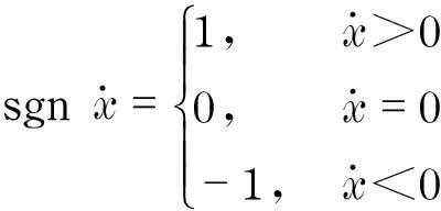
Thepolytropicexponentdependsontheheatexchangeconditions,sodifferenttestfrequencieshavedifferentpolytropicexponents.Withcertainpolytropicexponent,theairpressureonlydependsonvelocity,whichisinthemonotropicfunctionofthedamperlengthandhasnothingtodowiththepistonrelativevelocity.
(11)
3.3Dampingforce
Thehydraulicdampingsolelydependsontherelativevelocityofthepiston,regardlessofthepistonposition.
(12)
4 Data separation
Differentcharactersofdampingforce,airreboundforceandfrictioncanbeappliedtoseperateeachforcefromothers.Thedisplacementissinusoidalformwitharbitraryphaseandcanbewrittenas[14]
xi=X0cos [2πfλ(i-1)Δt+φ]
(13)
wherefλis test frequency,Δtissampleinterval, X0isdisplacementamplitude,andφisphase.Tomakeeverydisplacement-forcecurveunderdifferentfrequencieshavethesamedatalength,Δtcanbeexpressedas
Δt=Tλ/N=1/(Nfλ)
(14)
whereNis sample point number. Eq. (14) can be rewritten as
xi=X0cos[2πfλ(i-1)Δt+φ]=

(15)
Phaseφcanbeobtainedbynon-linearfitting,andthedisplacedatacanbetransferredintoastandardcosine.Withthesameprocedure,wegetthenewforcevectorF′itoensurethecorrespondenceoftheelementsintwovectors.
(16)
Thevelocityvectorcanbecalculated
(17)
whereτ=N/4. For vehicle shock absorber, hydraulic damping forces in compress and restore strokes are different. In compress stroke, the damping force can be expressed as
(18)
Theminusinfrontofcp1is to ensurecp1>0 andcp2>0. For restore stroke, the damping force is
(19)
Sothewholetestdatacanbedividedintocompressstrokeandrestorestroke.
(20)
whereS=N/2.
(21)
(22)
Subscriptpdenotes compress stroke, while subscriptrrestore stroke. Fore compress stroke:
Fpi=Fpci+Fpgi+Fpfi
(23)
According to Eqs.(6) (10) (18), the vector forms of different forces can be calculated as
(24)
(25)
(26)
where γj,cp1,cp2andFpfjareunknownparametersneedtobecalculated, jistestnumber, iisseriesnumberinvector.Sincetheairreboundforceisnonlinear,linearizationisusedtoavoidsolvingnonlinearequationset.Moretestsprovethatpolytropicexponentisdependedontestfrequency,closingto1.3incommontestfrequencieswithdifferencelessthan0.05.Soitcanbeexpressedas
γj=1.3+εj
(27)
with εjbeinglessthan0.05.ThenonlinearpartinEq. (24)canbeexpressedas
(28)

(29)

(30)
Thereboundforcecanberewrittenas
(31)
Stillsophisticateinappearance,thereboundforcehasalreadybeenconvertedintolinearfunctionofεj.Leastsquaremethodcanbeintroducedtocalcualteothersunknownparameterstoachievetheseparationofeachforce.
(32)
Rewrite Eq.(32) by known parameters:
Fpgi=αi+εjβi
(33)
where αiandβicanbeworkedoutbyypi,sotheforceequationcanbeexpressedas
(34)
Introduce a new matrixAas
(35)
We can transform Eq.(34) as
(36)
PremultiplyATtobothsidesofEq.(36)
(37)
The least squares solution of these parameters can be finally work out as
(38)
Thesameprocedurecanbeusedinrestorestroke.
5 Validation of the result with experiment
An air filling shock absorber is adopted for the validation. The test rig is provided by MTS Co. The statistic test is carried out to identify the parameters shown in Fig.5. Four different exciting velocities, 0.16 m/s, 0.32 m/s, 0.52 m/s and 0.64 m/s, are used to obtain the displacement-force curves. The data is used as the input of separation calculation. Then the absorber’s pressure air is released by drilling a hole in the outer tube. The tests are carried out with these exciting velocities as above to obtain the force data without air rebound force. The comparison of different test speeds data without pressure air with the calculation results with air rebound force is carried out as shown in Figs.6-9.
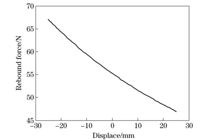
Fig.5 Displacement-force curves

Fig.6 Test data and calculation data at speed of 0.64 m/s
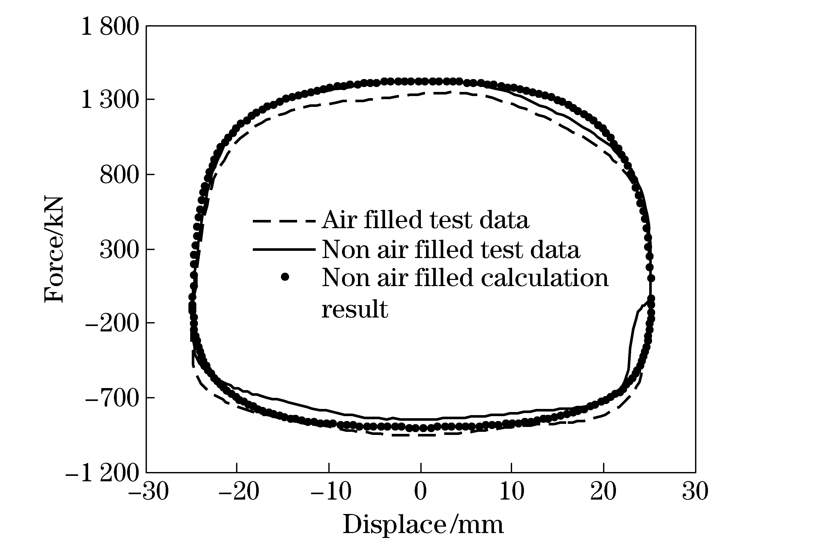
Fig.7 Test data and calculation data at speed of 0.52 m/s

Fig.8 Test data and calculation data at speed of 0.32 m/s

Fig.9 Test data and calculation data at speed of 0.16 m/s
6 Conclusion
Based on the different characteristics of damping force, air rebound force and friction force, a separation method is proposed. The calculation result is quite close to the test data, which make it usable for engineering application. The difference between calculation and test data may be caused by “filling defects because of the lack of oil”.
[1] Cao Dongpu, Song Xubin. Editors’ perspectives: road vehicle suspension design, dynamics, and control[J]. Vehicle System Dynamics, 2011, 49(1): 3-28.
[2] Tan Cao, Liu BaoJi, Yu Defu. Suspension air filling twin-tube shock absorber external characteristic research report[J]. Journal of China Ordnance, 1997(2): 47-54. (in Chinese).
[3] Besinger F H, Cebon D J, Cole D J. Damper models for heavy vehicle-ride dynamics[J]. Vehicle System Dynamics, 1995, 24(1), 35-64.
[4] Mollica R, Youcef-Toumi K. A nonlinear dynamic model of a monotube shock absorber[C]∥Proceedings of the American Control Conference, Albuquerque, NM, USA, 1997.
[5] Smlms A, Crolza D. The influence of damper properties on vehicle dynamic behavior, SAE Paper, 2002-01-0319[R]. Warrendale, PA, USA: Society of Automotive Engineering, 2002.
[6] Liu Yanqing, Zhang Jianwu. Nonlinear dynamic responses of twin-tube hydraulic shock absorber[J]. Mechanics Research Communications, 2002(29):359-365. (in Chinese).
[7] Herr F, Mallin T, Lane J, et al. Flow analysis and modeling of shock absorbers[C]∥Proceedings of the 1998 ASME international mechanical engineering congress and exposition, Anaheim, CA, New York, 1998.
[8] Fash J W. Modeling of shock absorber behavior using artificial neural networks SAE Paper 940248[R]. Warrendale, PA, USA: Society of Automotive Engineering, 1994.
[9] Duym S, Stiens R, Reybrouck K. Evaluation of shock absorber models[J]. Vehicle System Dynamics, 1997(27): 109-127.
[10] Cossalter V, Doria A, Pegoraro R, et al. On the non-linear behavior of motorcycle shock absorbers[J]. Journal of Automobile Engineering, 2010, 224(1): 15-27.
[11] Lion A, Loose S. A thermomechanically coupled model for automotive shock absorbers: theory, experiments and vehicle simulations on test tracks[J]. Vehicle System Dynamics: International Journal of Vehicle Mechanics and Mobility,2002, 37(4):241-261.
[12] Dixon J C. The shock absorber handbook[M]. New York: John Wiley and Sons, Ltd, 2007: 257-258.
[13] Czop P, Stawik D. A high-frequency first-principle model of a shock absorber and servo-hydraulic tester[J]. Mechanical Systems and Signal Processing, 2011, 6(25): 1937-1955.
[14] Kruse A, Eickhoff M, Tischer A. Analysis of dynamic behavior of twin-tube vehicle shock absorbers[J]. SAE International Journal of Passenger Cars: Mechanical Systems, 2009, 2(1): 447-453.
(Edited by Cai Jianying)
10.15918/j.jbit1004- 0579.201524.0210
U 463.33+5.1 Document code: A Article ID: 1004- 0579(2015)02- 0201- 06
Received 2013- 11- 05
E-mail: vdmm@bit.edu.cn
杂志排行
Journal of Beijing Institute of Technology的其它文章
- Nonlinear symbolic LFT model for UAV
- Novel scheme of high precision inertial measurement for high-speed rotating carriers
- Study on influencing factors of adapters separating with the underwater missile
- Fast-solving method for air-to-surface guided bombs’ allowable attack area
- Design and analysis of mechanical self-destruction and self-neutralization mechanism for submunition fuze
- Resilience approach for heterogeneous distributed networked unmanned weapon systems
