Modeling and simulation of the static characteristics of diaphragm spring clutches
2015-04-22XIJunqiang席军强LUJia鲁佳PANChun潘春
XI Jun-qiang(席军强), LU Jia(鲁佳), PAN Chun(潘春)
(School of Mechanical Engineering, Beijing Institute of Technology, Beijing 100081, China)
Modeling and simulation of the static characteristics of diaphragm spring clutches
XI Jun-qiang(席军强), LU Jia(鲁佳), PAN Chun(潘春)
(School of Mechanical Engineering, Beijing Institute of Technology, Beijing 100081, China)
The diaphragm spring clutch static characteristics to improve the starting quality for cars equipped with automated mechanical transmission (AMT) were modeled and simulated. First, axial stiffness of clutch cushion spring and characteristic curves of diaphragm spring were theoretically and experimentally studied. Then, model of transfer characteristics of the normal force was built, with special conscen on the abrasion of friction discs and the influence of temperature to diaphragm spring. Finally, the model was tested in practicalstarting for cars equipped with AMT, which showed that the starting quality was significantly improved. The experimental results showed that the proposed model was precise enough to be implemented conveniently.
clutch; diaphragm spring; cushion spring; simulation; elastic characteristics
The accurate prediction of the torque transmissibility in clutch system is the key element in automated manual transmission (AMT) system. In order to reduce the impact and the slipping work in the process of starting or shifting, many studies have been focused on the modeling of clutch[1-6]. At present, formulaTc=μcFcRcZis used in most of the models, whereμc,Fc,Rc,Zindicate the dynamic friction, the normal force on the clutch plate, the diameter of the friction, and the number of friction surfaces, respectively. In such models, it is difficult to evaluate the normal force on the pressure plate that determines the torque transmitted.
In this paper, how the diaphragm spring and the cushion spring participate in the transmissibility characteristic was studied. The relationship between the release bearing position and the normal force on the pressure plate was analyzed by creating the static model of diaphragm spring clutch.
1 Components of clutch system
A dry-clutch system mainly consists of a flywheel, a pressure plate, clutch discs, release bearing and clutch cover (Fig.1). The crankshaft, pressure plate and diaphragm spring always keep rotating whether the clutch engages or separates. The diaphragm spring transforms a release bearing displacement into a corresponding displacement of the pressure plate. In the process of engagement, there are three phases. The first phase is not over until the spring begins to be compressed by the pressure plate, which ensures the desired engagement smoothness. In the last phase, the cushion spring is completely compressed,and the pressure plate presses the clutch disc against the flywheel and the torque transmits from the engine to the gearbox. The normal force on the pressure plate depends on the load-deflection characteristics of the diaphragm spring. The process of disengagement is opposite from engagement. To obtain the normal force transmissibility characteristic, the axial stiffness of cushion spring and the load-deflection of the diaphragm spring is required.

1-Crankshaft; 2-Flywheel; 3-Friction pad; 4-Cushion spring; 5-Pressure plate; 6-Clutch disc; 7-Diaphragm spring; 8-Release bearing; 9-Main shaft;10-Clutch cover
2 Establish static model
2.1 Characterization of cushion spring
The DS430 clutch produced by Changchun Yidong Co. Ltd. was studied in this paper. The compression characteristic of its cushion spring in the axial direction was achieved through experimental tests in accordance with the relevant standards[7]. As shown in Fig.2, the cushion spring was compressed by the cylinder with the set speed of 3mm/min. The displacement sensor and force sensor are used to acquire real-time data. Experimental tests were carried out on different samples to reduce the error.
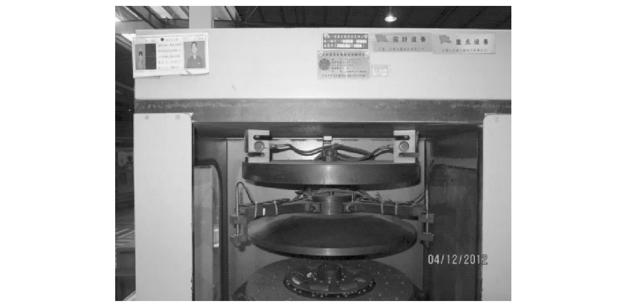
Fig.2 Experimental setup for characterization of the cushion spring
The model of cushion spring was built and simulated through Solidworks and ANSYS Workbench. The 3-D model and ANSYS model is shown in Fig.3. In ANSYS, by modeling, meshing, setting constraint and solving, the compression of the cushion spring was simulated so as to get the relationship between displacement and force. After simulation and experiments, the average curve of cushion spring characteristics is shown in Fig.4.

Fig.3 3-D model, mesh model, ANSYS model of cushion spring
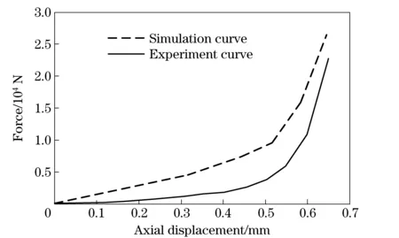
Fig.4 Compression characteristic curves of the cushion spring (experiment vs simulation)
It can be seen that the experimental curve agrees well with the simulation curve. The result shows that the axial force changes with cushion spring compression nonlinearly. The maximum compression of cushion spring is about 0.65 mm. Through the initial phase of compressing, the axial force grows slowly with the displacement. As the cushion spring gets to be completely compressed, the force increases sharply. The curve was rationale for the next modeling.
2.2 Load-deflection characteristic of diaphragm spring
Main methods describing the load-deflection characteristic of diaphragm spring areA-Lformula, finite element method and modifiedA-Lformula[8-10]. Several assumptions are used on deducingA-Lformula, which lead to the error from the experiment data. In this paper, the load-deflection characteristics were achieved by experimental test and modifiedA-Lformula. In addition, temperature was considered as a factor in the experiments.
According to theA-Lformula:
[(h-k1λ1)(h-0.5k1λ1)+t2]
(1)
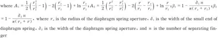
whereEis the modulus of elasticity,μis the Poisson’s ratio,Lis the external support radius,lis the inner support radius,Ris the outside radius,ris the inside radius,tis the thickness,his the free height,λ1is the axial displacement, andF1is the normal force. According to the structure parameters supported by the company, theA-Lformula can be written as

(2)
As shown in Fig.5, the experiments give the load-deflection curve of diaphragm spring. It can be seen that theA-Lformula curve doesn’t match the test data well as shown in Fig.6. So modified form ofA-Lformula is proposed[11]. Considering the influence the assumptions ofA-Lformula bring, three constants ofA,B, andCwere brought in to modify the formula.
[A(h-k1Cλ1)(h-0.5k1Cλ1)+Bt2]
(3)

Fig.5 Test setup for diaphragm spring
The coordinates of peak, valley and operating points in the experimental curve are used to solve the constants ofA,B, andC.
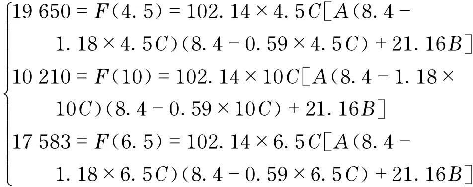
(4)
Solvingtheaboveequations,themodifiedformulacanbewrittento
F1=F(λ1)=90.49λ1[1.28(8.4-1.05λ1)×
(8.4-0.52λ1)+19.68]
(5)
The curves of test data,A-Lformula andmodifiedA-Lformula are plot in Fig.6. It can be seen that the peak ofA-Lformula is lower than the test data and the two curves deviates after the deflection 8 mm. The modifiedA-Lformula almost matches the actual data.
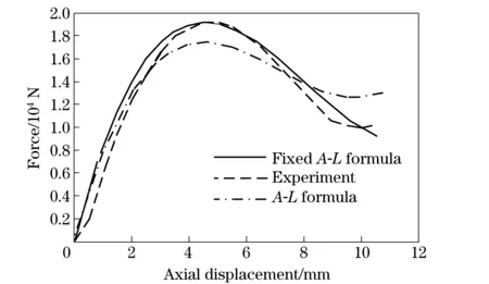
Fig.6 Load-deflection curves of test data, A-L formula, modified A-L formula
The influence of temperature to load-deflection characteristics was studied by testing the diaphragm spring at different temperatures. The result is shown in Fig.7. It can be seen that the curves decreases with temperatures.
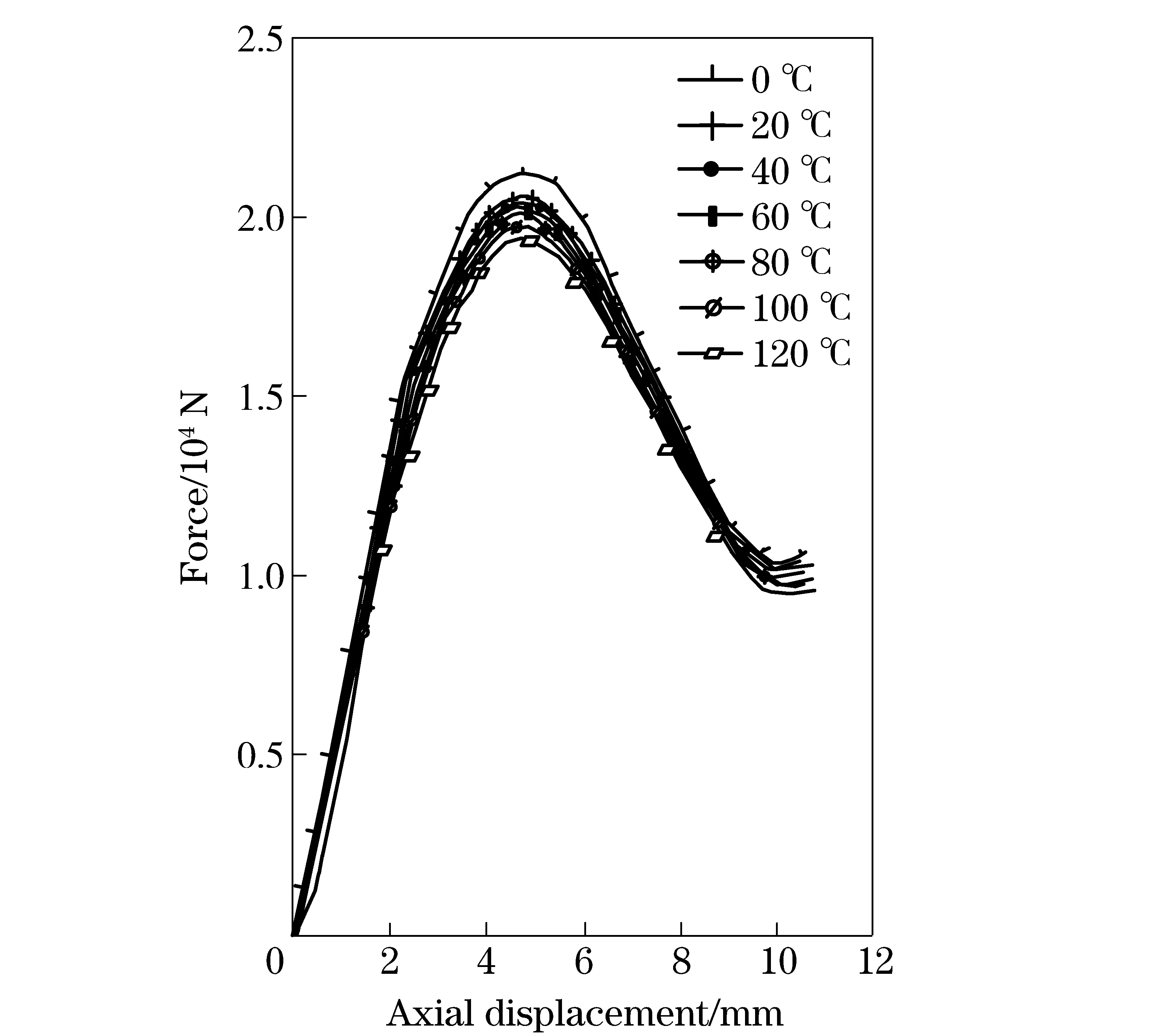
Fig.7 Experiment results of influence of temperature
2.3 Static models
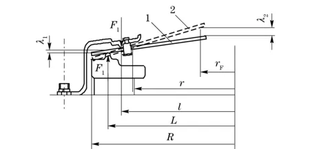
Fig.8 Process of installation of clutch
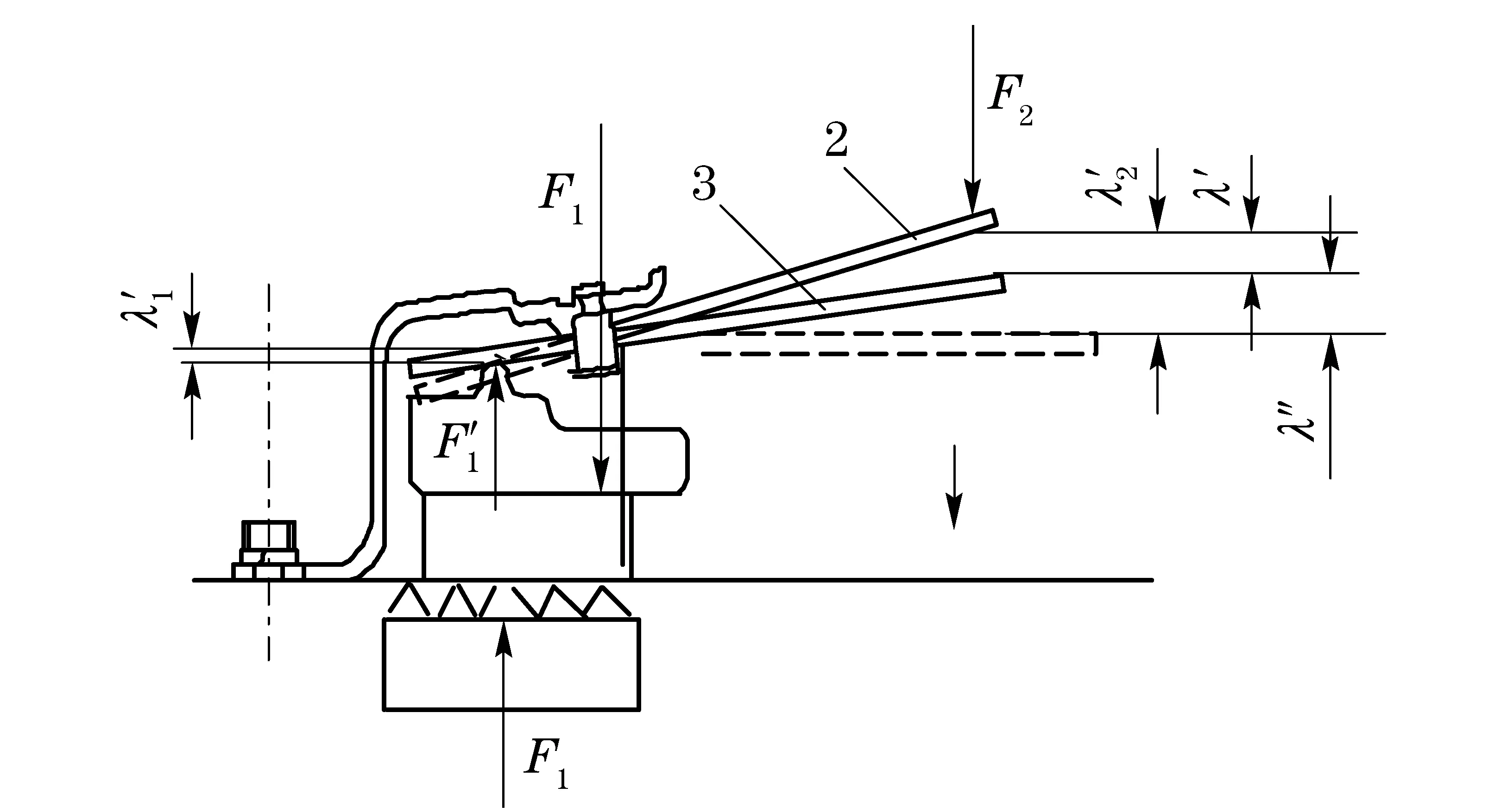
Fig.9 Process of working
After achieving the characteristics of diaphragm spring and cushion spring, the analyses of clutch working course are required to establish the static model. A zoom of the clutch operating scheme focusing on the displacement and force transmissibility is depicted in Fig.8 and Fig.9. Fig.8 shows the process of installation while Fig.9 shows the process of working. The researches about the relationship between forces and displacements are as follows. The variables in Fig.8 were illustrated in section 2.2. The positions of the initial states are defined as zero points. Phase 1 is the initial state while phase 2 is the installed state (engaged state). In the installation of clutch, the deflection of disc part of diaphragm spring generates a corresponding force of the pressure plateF1. According to lever principle, the relationship between the displacement of release bearingλ2and the displacement of diaphragm springλ1can be written as
(6)
Phase3isthedisengagedstatewhilephase2istheengagedstate.TheclutchdiscismovedawayfromtheflywheelbytheforceofthereleasebearingF2. The displacement of diaphragm spring isλ′1, while the displacement of throw bearing isλ′2, which consists ofλ′ (rigid deformation of diaphragm spring) andλ″ (bending deformation).λ′ can be calculated by
(7)
Accordingtothedeformationformulaofmaterialmechanics,λ″ can be computed as
(8)
Inordertoachievethetransmissibilitycharacteristicofnormalforce,thestaticmodelisimplementedbasedontheMATLAB/SIMULINK,asshowninFig.10.Fig.11isthesimulationblockdiagram.ThemodelusestheEqs.(5)-(8)whichcontainthecharacteristicsofcushionspringanddiaphragmspring.Ittakesthedisplacementofreleasebearingastheinputandthenormalforceonplateastheoutput.
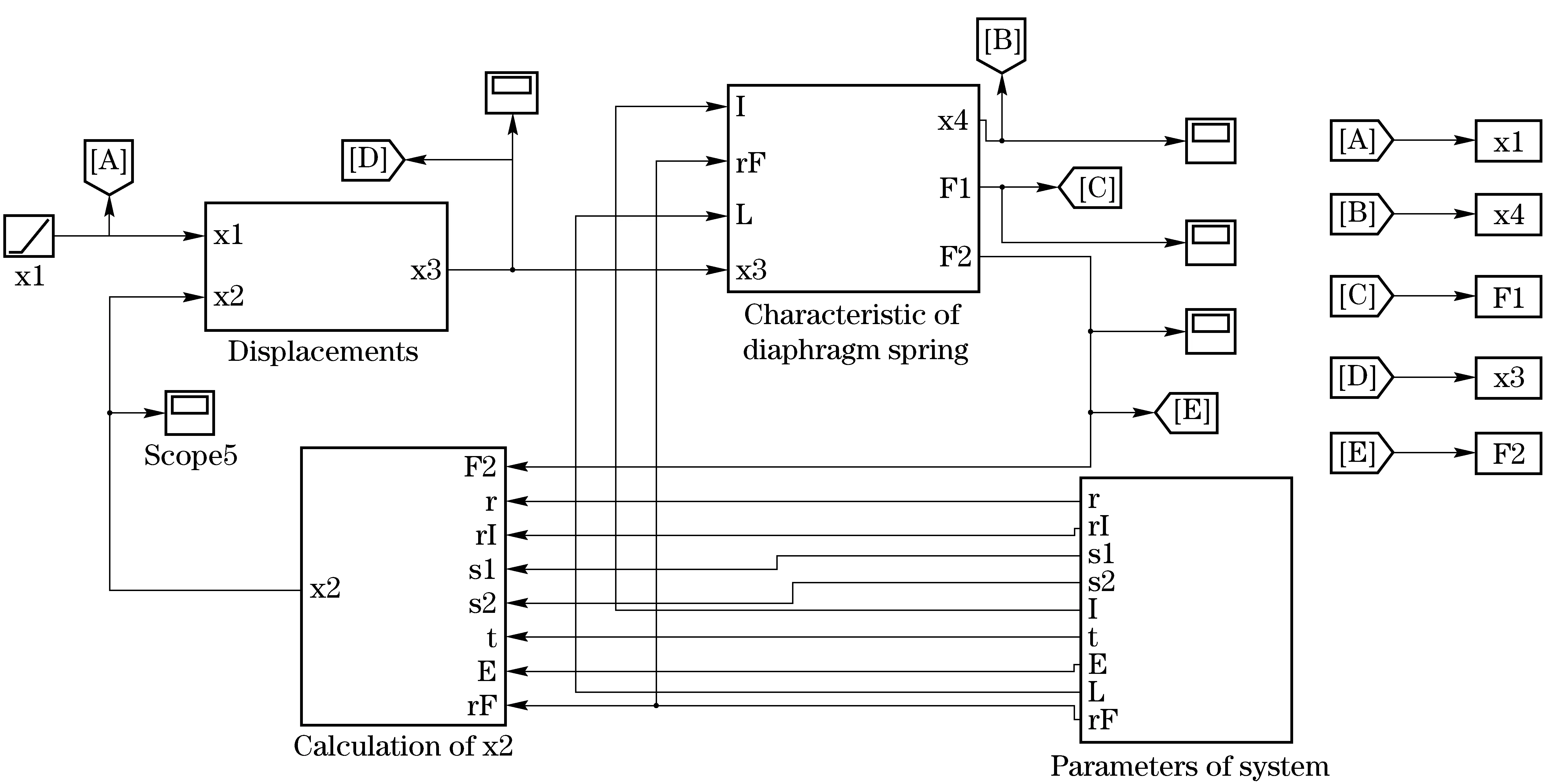
Fig.10 Simulation model of transmissibility characteristic of normal force
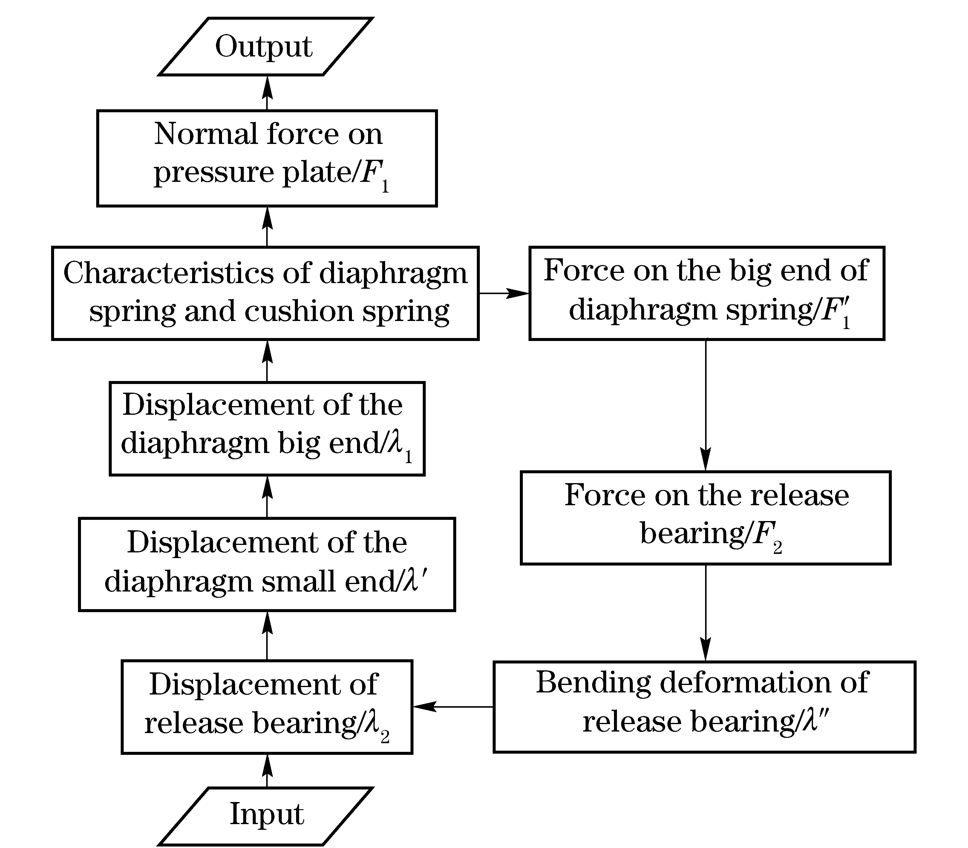
Fig.11 Simulation block diagram
2.4Simulationresult
Aftersettingthegeometryparametersofthesystem,thesimulationresultisshowninFig.12.Theinstallationprocessisfromzeropointtopointa. After pointa, the clutch begins to disengaged. The normal force decreases sharply at first and then decreases slowly to zero. In this period, slight changes in the displacement can cause huge changes in the normal force. After pointb, the flywheel is completely separated from diaphragm spring and the normal force on the pressure plate gets to zero.
In this paper, the influence of the abrasion of the friction plate is considered in the fix of the model. As shown in Fig.12, pointa′ is the working point after wearing. It can be seen that the transmissibility characteristic of new curve deviates from the old one. In addition, based on the research in section 2.2, the model takes temperature into account. The simulation result influenced by temperature is shown in Fig.13. Every temperature and every displacement of release bearing correspond to a certain force.
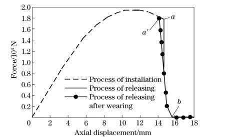
Fig.12 Simulation result

Fig.13 Simulation result of different temperatures
3 Application of the model in a real car
In order to verify the accuracies of the model,we designed a strategy aimed at controlling the normal force in AMT system. The control structure of normal force is shown in Fig.14. The algorithm used the throttle opening, engine speed, the growth rate of engine speed and the driven plate speed to decide the required torque to ensure the smoothness of vehicle. The displacement of oil cylinder and normal force on the pressure plate were acquired through the model. The pulse width of proportional valves was modulated by TCU in the engagement of clutch.
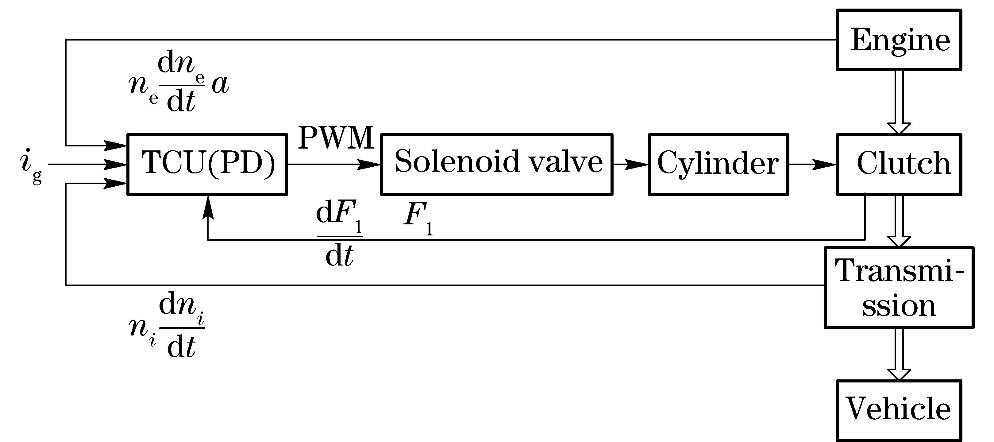
Fig.14 Control structure of normal force
Through the test in a real car, the data were acquired by the sensors. As shown in Fig.15, the speed of the engagement of clutch was fast at first and became slower when the torque began to be transmitted. In the process, the rate of the change of driven plate speed was smooth and the performance of starting was good.
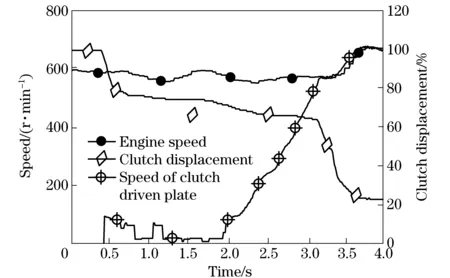
Fig.15 Test data of starting process
4 Conclusion
In this paper, a static model of diaphragm spring clutch was developed based on the research on the axial stiffness of cushion spring and the load-deflection of the diaphragm spring. Temperature and friction were considered in the model. The simulation results showed how the normal force on the pressure plate was changed by the displacement of the release bearing. At last, the model was applied in a car’s starting process and the results showed that the model was precise enough and start quality was improved significantly.
[1] Vasca F,Vasca F, Lannell L,et al.Torque transmissibility assessment for automotive dry-clutch engagement[J]. IEEE ASME Transactions on Mechatronics, 2011, 16(3): 564-573.
[2] Lucente G,Montanari M, Rossi C. Modelling of an automated manual transmission system [J]. Mechatronics, 2007, 17(2-3): 73-91.
[3] Glielmo L,Vasca F.Optimal control of dry clutch engagement[C]∥SAE 2000 World Congress,Detroit,MI,United States, 2000.
[4] Zhang Tai,Ge Anlin,Song Chuanxue,et al.The test and research of AMT start and shift of off-road vehicle[J]. Automotive Technology, 2006(4):27-30.(in Chinese)
[5] Xiao Yongming,Sun Dongye,Qin Datong,et al.Research on patial fuzzy control of car clutch in starting phase[J]. Automotive Technology, 2008(12):12-15. (in Chinese)
[6] Lu Jia, Liu Haiou, Peng Jianxin, et al. Research on hill-start control strategy for military heavy-duty wheeled vehicles with AMT[J].Ordnance Technology, 2013,34(8):929-934. (in Chinese)
[7] National Development and Reform Commission. QC/T 27—2004, Car dry friction clutch assembly bench test method [S].Beijing: China Planning Press, 2004.(in Chinese)
[8] Zhang Tieshan. Discuss on assumptions of the Almen-Laszlo equation for diaphragm spring[J].Proceedings of the Automobile Technology,2003(12):12-14.
[9] Ren Tao,Wen Daohua, He Dazhi, et al. Finite element analysis of diaphragm spring[J]. Journal of Changchun University of Science and Technology, 2010,33(4):92-94. (in Chinese)
[10] Lin Shiyu.The design and manufacture of the diaphragm spring clutch disc spring[M].Nanjing: Southeast University Press, 1995.(in Chinese)
[11] Almen J O, Laszlo A.The uniform section disc spring[J].Transaction of the ASME,1936,58(10):305-314.
(Edited by Cai Jianying)
10.15918/j.jbit1004- 0579.201524.0208
U 463.211 Document code: A Article ID: 1004- 0579(2015)02- 0188- 06
Received 2013- 08- 20
Supported by the National Natural Science Foundation of China(51275038)
E-mail: XJQ@263.net
杂志排行

Journal of Beijing Institute of Technology的其它文章
- Nonlinear symbolic LFT model for UAV
- Novel scheme of high precision inertial measurement for high-speed rotating carriers
- Study on influencing factors of adapters separating with the underwater missile
- Fast-solving method for air-to-surface guided bombs’ allowable attack area
- Design and analysis of mechanical self-destruction and self-neutralization mechanism for submunition fuze
- Resilience approach for heterogeneous distributed networked unmanned weapon systems