ND e s i g no f a nH-s h a p e dS l o t Mu l t i-f r e q u e n c y Mi c r o s t r i pA n t e n n a
2014-12-23YANGHongMOUHongjiang
YANG HongMOU Hong-jiang
(College of Electrical Engineering,Chongqing University of Posts and Telecommunications,Chongqing 400065,China)
0 Introduction
The rapid development and application of wireless communication technology push modern communication antennas to miniaturization,multi-band,multipolarization.Microstrip antenna got widespread attention and application with its smallsize,light weight,low cost,dual polarization and dual-band,and many other advantages[1].Miniaturization and wideband become an inevitable trend in the development of microstrip antennas.Reference[2]put forward a kind of h form patch microstrip antenna,it not exist other unwanted frequency;Literature[3]added short circuit needle in the H form antenna to achieve doublefrequency effect;Literature[4]used the u-shaped aperture loading H form structure which realized the miniaturization and dual-band.This paper adopted double dielectric substrate,h-shaped slot antenna realized miniaturization and multi-frequency.
1 Research and verify microstrip antenna with two layers of substrate designformula
Microstrip antenna with two layers of substrate which put one substrate as meet floor,and in another layer surface use photolithography corrosion method to make certain shape metal strips as a microstrip radiation unit,with microstrip lines or coaxial way to feed.
Assuming the total double-layer dielectric substrate thickness is h,the thickness of the sublayer is h1,the double medium substrate relative effective permittivity and the relative effective permeability[5-6]:

Whereq1、q2are the fill factor respectively for the upper substrate and the sublayer on equivalent medium substrate which determined by two kinds of material area ratio.

Where:

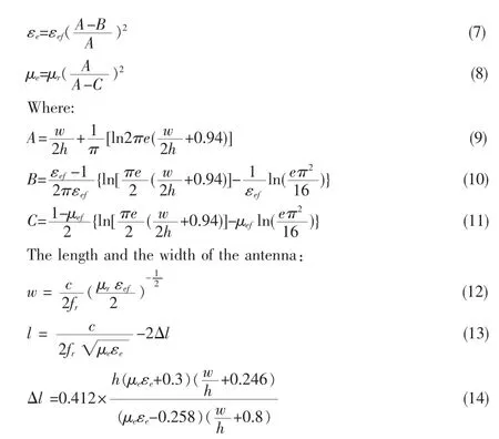
Here c for the speed of light,frfor the resonance frequency of the antenna,w1is the practical width of the two layered substrate.According to media substrate dual relationship[7]and Pucel formula[8],get the base plate of the equivalent permittivity and permeability:

This microstrip antenna operated at fr=2.40GHz which feed with Coaxial line.the sublayer medium plate adopted the Terfenol-D materials(μr=9.30)and the upper Rogers R03210 medium boards dielectric constant εr=10.20,the substrate thickness h =3.00mm,h1=1.50mm,calculated the size of the antenna w=21.20mm,l=14.20mm.According to the general two-layered structure design the antenna,its return loss curve shown in figure 1:

Fig.1 Return loss of two-layered microstrip antenna
From the return loss graph we can see the antenna opperated at 2.40GHz,verify the correctness of the above formula which give a initial reference for two-layered substrate microstrip antenna design.
2 h-shaped slot microstrip antenna design
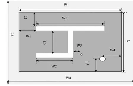
Slot an h-shaped gap on the rectangular metal patch can extend the current path,reduce the resonance frequency,decrease the relative size of the antenna,and opperate at high frequencies.Calculated the antenna size with formula above,combined with h-shaped aperture structure,change the feeder position,and get the antenna structure as shown in figure 2,rectangular patch center coincide with the center of the substrate medium,gap width 1.00 mm.

Fig.2 h-shaped slot antenna structure
According to the formula(1~14)calculated the antenna length and width,according to the antenna chart 2,preliminary design the antenna size shown in table 1.

Tab.1 Parameter of antenna(unit:mm)
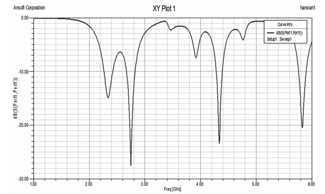
The antenna return loss figure shown in figure 3 which get simulation results with software Ansoft HFSS 11.0:

Fig.3 Return loss of general h-shaped slot antenna
When return loss less than-10 dB,the microstrip antenna has four working band:2.26~2.42GHz,2.67~2.82GHz,4.28~4.39GHz,5.76~5.89 GHz.The antenna realized multi-band design,but relative bandwidth is narrower,so the next phase can slot in the ground plate to reduce resonance frequency,increase bandwidth.
3 Conclusion
This paper deduced the two-layered substrate microstrip antenna design formula,provided the theoretical support for this kind of antenna design.By slotting an h-shaped on rectangular patch that achieve multifrequency characteristics of the antenna realization broadband and miniaturization.But at the same time we also noticed that bandwidth is narrower.At a later time wo can slot in the ground plate and plus shortcircuit pin to increase bandwidth.
This research was supported by the Science Technology of The Chongqing Education Commission (KJ100512),and the Natural Science Foundation of Chongqing province of China(CSTC 2010BB2412).
【Reference】
[1]D.M.Pozar,D.H.Schaubert.Microstrip Antenna Design[M].IEEE Press,1995.
[2]Huang Zhen-hua,Zhou Xi-lang,Niu Jia-xiao.Novel Design of an H-shaped Dual-frequency Microstrip Antenna[J].Journal Of Microwaves,Vol.23 Supplement,2007,8:17-20.
[3]S C Gao,L W Li,T S Yeo,et al.A Dual-frequency Small Microstrip Antenna[C].Antennas and Propagation Soc.Int.Symposium,2001,4:86-89.
[4]Qi Dong-sheng,Li Bin-hong,Liu Hai-tao,Zhang Ya-bin.Slot-loaded H-shaped Dual-frequency Antenna[J].Chinese Journal Of Radio Science,2004,vol.19(1):95-98.
[5]Yu Yong-jie,Yang Cheng-tao.Bilayered Magnetoelectric Composites Substrate Microstrip Antenna Design and Application[J].ACTA ELECTRONIC SINICA,2010,38(9):2021-2024.
[6]Wu Zhengzhong.Study of Theory,Model,Simulation and Characteristic of RFMEMS Antennas[D].Chongqing:Chongqing University,2002.
[7]Harold A.Wheeler.Transmission-Line Properties of Parallel Strips Separated by a Dielectric Sheet[J].IEEE Trans on MTT,1965,13(3):172-186.
[8]Robert A.Pucel.Microstrip Propagation on Magnetic Substrates--PartI:Design Theory[J].IEEE Trans on MTT,1972,20(5):526-531.
[9]R.Waterhouse.Small Microstrip Patch Antenna [J].Electronics Letters,1995,31(8):604-605.
