Polarization state measurement based on photoelastic modulation
2014-09-07GAOTingtingHANHuilian
GAO Ting-ting, HAN Hui-lian
(Science and Technology on Electronic Test & Measurement Laboratory, North University of China, Taiyuan 030051, China)
Polarizationstatemeasurementbasedonphotoelasticmodulation
GAO Ting-ting, HAN Hui-lian
(ScienceandTechnologyonElectronicTest&MeasurementLaboratory,NorthUniversityofChina,Taiyuan030051,China)
Abstract:Polarization coding is a specific encoding method by using the polarization state of optical signal carrying coded information.It focuses on nonlinear effects, polarization mode dispersion and other issues in high-speed fiber-optic communications.This paper presents a measurement method for polarization state based on elastic-optic modulator.This method not only retains the original advantages of elastic-optic modulator for polarization measurement, but also overcomes the defects of existing methods including high modulation frequency and invalid collection by using array detector.Matlab simulation and experimental verification scheme are given.The feasibility of this method is verified through theoretical analysis, and simulation and experimental results are carried out.The error analysis of the measurement results shows that the method can meet the measurement requirements and provide conditions for using the polarization encoding in high-speed communication.
Key words:stokes parameter; difference frequency modulation; polarization measurement; polarization encoding
CLDnumber: TN929.11Documentcode: A
Since 40 Gbit/s high-speed fiber-optic communication was proposed, some new coding format have emerged consequently, such as signal sideband return-to-zero (SSB-RZ) code, carrier-suppressed return-to-zero (CSRZ)[1]code and the secondary coding techniques[2-3].Combined with the new pattern of the secondary coding, such as carrier-suppressed return-to-zero differential phase shift keying (CSRZ-DPSK) and other encoding formats, the new one can not only reduce the intrinsic dispersion and polarization mode dispersion (PMD)[2], but also increase the transmission rate and transmission distance to a certain extent.Although this new encoding format shows a certain improvement for transmission performance of high-speed fiber-optic communication system, it is still difficult to solve nonlinear effects and PMD problems caused by the huge power consumption.Encoding parameters available include basic light intensity, phase (including frequency) and polarization.The first two parameters are widely used in low-speed areas, but there are some difficulties to solve these problems in some high-speed areas.Therefore, people began to turn their attention to polarization encoding, which is called polarization phase-shift keying (PolSK).Polarization coding is an encoding method, which uses the polarization state of the optical signal carrying coded information.This method is becoming particularly important.Therefore, polarization measurement gradually causes wide public concern in the field of high-speed fiber-optic communications.
Currently, polarization measurement methods can be divided into three categories: one is the electro-optic modulation[4], another one is liquid crystal phase retardation, France (LCVR)[5], and the third is the elastic optical modulation method[6-7].Photoelastic modulator is a polarization modulator running at the resonant frequency of the state.It is composed of isotropic material spectra and has sharp contrast with the double-refraction materials.Based on these two properties, photoelastic modulator has a unique optical properties such as high modulation accuracy, high modulation efficiency, wide band (from vacuum ultraviolet to infrared), high energy efficiency, large acceptance angle range, chase aperture (about 40°), and precisely controlled phase delay.These features make photoelastic modulator act as an efficient polarization modulator used in various study fields such as biological physics and physical chemistry.Photoelastic modulator is the only option in the high-sensitivity measurement field, which enables automatically polarized spectral measurements[8].
There are two methods for elastic polarized light modulation measurement: using the first method, through a one-time measurement for four different frequency components of phase-lock, the Stokes vector is obtained.But the phase-locked frequency is an integer multiple of the driving frequency, which leads to ineffective collection by using capture detector array.The second method makes the measurement by using difference frequency modulation, but the offset frequency by this method is low and it can only get two values of Stokes vector.In order to solve the above shortcomings, the paper proposes a three elastic-optic modulator polarimetric method.Three Stokes vectors can be obtained once by measuring the difference between each signal, which well compensates the deficiencies of the existing polarization spectral information technology.
1 Measurement principle
1.1 Stokes parameters description and photoelastic modulation
There are four ways to describe the polarization state of light completely[9-10]: trigonometric notation, Jones vector notation, Stokes vector notation and Poincare sphere notation.Stokes vector notation was first proposed in 1852 by using four Stokes parameters to describe intensity and polarization of any light wave.The described light can be completely polarized light, partially polarized light, light, monochromatic light and non-monochromatic light.Furthermore, the four Stokes parameters are the time average of the light intensity and can be measured directly, therefore, Stokes vector notation is commonly used in the measurement process.Stokes vector is defined as
whereExandEyrepresent the electric field amplitude ofxandydirection, respectively;δxandδyindicate the direction of the phase; 〈〉 represents the average value of the time;S0represents the total intensity of light;S1represents the intensity difference between lightxandycomponents;S2represents the intensity difference in the direction of +45 ° or -45° linear polarization component;S3represents the intensity difference between right-hand circularly polarized light component and the left-hand one.
Photoelastic modulator is a kind of device based on photoelastic effect of high-performance transparent optical materials such as fused silica, lithium fluoride and calcium fluoride crystals.By having some mechanical forces with periodic change on piezoelectric materials (e.g.piezoelectric quartz crystal, piezoelectric ceramic, etc.), resonance of optical materials occurs, and then a stress standing wave emerges.Due to photoelastic effect, there will be birefringence of optical material which changes periodically.As a result, polarization modulator is achieved by changing the polarization state of the light transparent material[11].The variable delay, namely phase change of two mutually vertical polarization components of fused silica glass, is obtained for the device as
δ(t)=Asinwt,
(2)
andAis the amplitude of the delay,
(3)
wheredis the thickness of the fused silica glass,λis the corresponding wavelength of light,Vmis the voltage peak applied to the piezoelectric quartz crystal provided by the drive control circuit[12], andKis the coefficient associated with quartz glass and piezoelectric quartz crystal.
1.2 Polarization measurement principle
The schematic diagram of three elastic-optic measured polarization light modulator is shown in Fig.1.
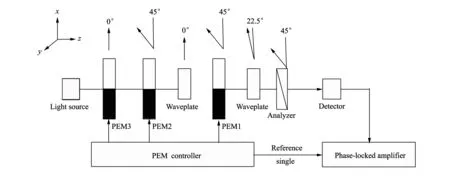
Fig.1 Schematic diagram of measured polarization based on 3-PEM
When light beam and matter interact, the Stokes vector of beam and the Stokes vector of incident beam have linear function relation.In other words, a beam of light passing through modulation, 1/4 wave plate, 1/2 wave plate and partial detector, the Strokes vector can be described as
(4)


(5)

wheremis an odd number;nis the even number;K=1/2, whenn=0 orm1=n2=0; in other conditions,K=1.
It can be seen from Eq.(7) that based on the phase-locked amplifier technology, choosing drive signal after optical modulator as a reference signal, the amplitudes of DC component and the light intensity with the frequencies of 2(w1-w2),w2-w3andw1-w3from the output signal of the detector are calculated as
(8)
S1,S2andS3can be obtained by Eq.(8).
2 Simulation
Using Matlab software for simulation and analysis to prove the feasibility of the method.
I=1.0,Q=0.5,U=0.3 andV=0.4; Three driving frequencies aref1=50.10 kHz,f2=50.08 kHz andf3=49.98 kHz,ωi=2πfi(i=1,2,3); Phase delay amplitudesα01=α02=α03=π.Substituting the above parameters into Eq.(5), eliminating the high-frequency components, then the low-frequency curveS0can be obtained, as shown in Fig.2.Frequency component 2(w1-w2) ofS1contained in Eq.(5) is shown in Fig.2(b), frequency componentw2-w3ofS2is shown in Fig.2(c), frequency componentw1-w3ofS3is shown in Fig.2(d).

Fig.2 Frequency curves of S0, S1, S2 and S3

3 Error analysis
The above calculation and simulation results are the prerequisite required to guarantee the measured light vertically incident photoelastic modulator, but any small changes in the angle will cause wrong results in practical application.The change of angle will finally change the phase delay amplitude.The reasons for phase delay change are as follows: Firstly, the changing angle will cause change ofdin Eq.(3), leading tod′=d/cosθ′(θ′ is the light through the crystal elastic light refraction, it satisfies the law of refraction).Secondly, the angle of incidence is not equal to zero due to the path of light through different stress-induced changes in the phase delay.In the case of small angle, the first reason has little effect on the results and can be ignored, but the second has a major effect.By analyzing the incidence of minor deviations from the simulation results, combining Eq.(8), assuming that elastic optical material is fused silica, the errors ofS1andS2due to the phase delay deviation from 1%-10% are shown in Fig.3.
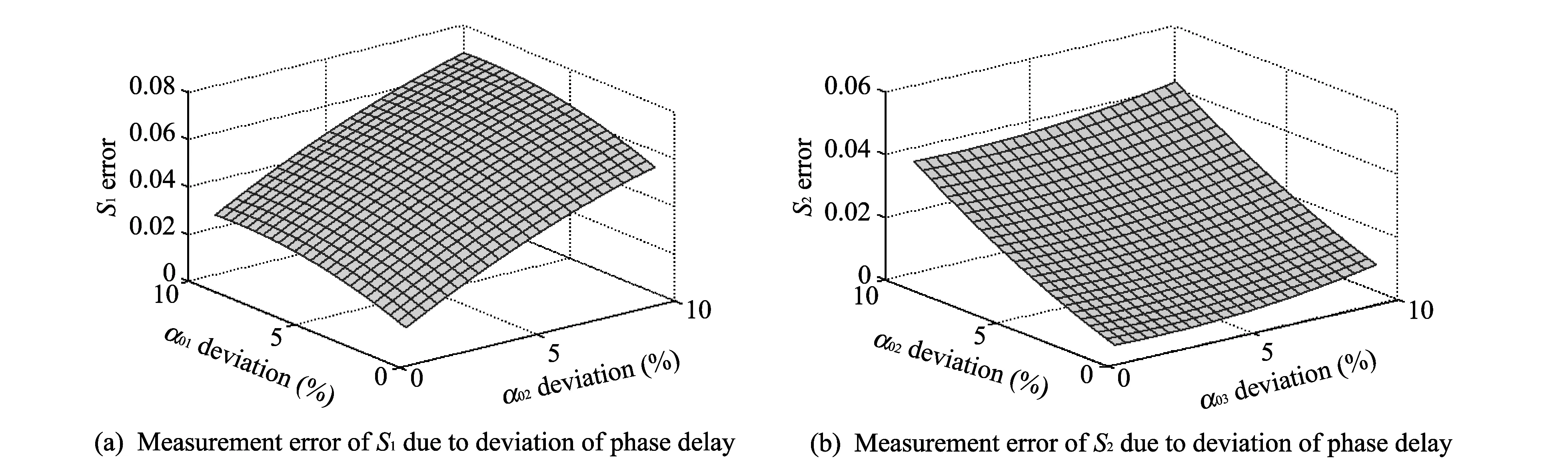
Fig.3 Measurement errors of S1 and S2
Fig.3(a) shows that when the magnitude of the phase delaysα01andα02reach 10% simultaneously, the error ofS1is 6.8%.Fig.3(b) shows that when the magnitude of the phase delaysα02andα03reach 10% simultaneously,S1error reaches 4.2%; Similarly, whenα01andα03reach 10% simultaneously,S1error is 4.2%.It can be seen that as the deviation of magnitude and the phase delay increase, the Stokes vector measurement error increases, therefore the actual measurement should minimize the phase delay variation.
4 Experiment and analysis
The feasibility can be verified by the following experiments.Experimental equipment is shown in Fig.4.Photoelastic crystals are Zn Se in PEM1, PEM2 and PEM3, piezoelectric crystal uses quartz.PEM1 driving frequency isf1=(50.10/2π) kHz, PEM2 driving frequency isf1=(50.08/2π) kHz, PEM3 driving frequency isf1=(49.98/2π) kHz.In order to observe it easily, the laser with wavelength of 632.8 nm is chosen.

Fig.4 Experimental equipment
To facilitate analysis, test signal is collected by NI PXI-5122 data acquisition card (see Fig.4).The signal passes through the low-pass filter with a 150 Hz cutoff frequency by LabVIEW.The spectrum of the signal is shown in Fig.6.

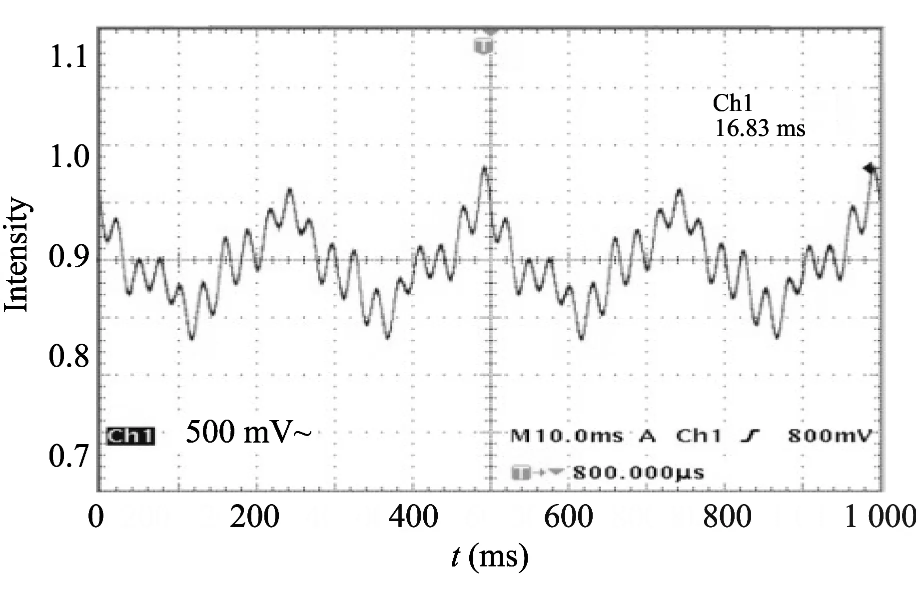
Fig.5 An oscilloscope diagram
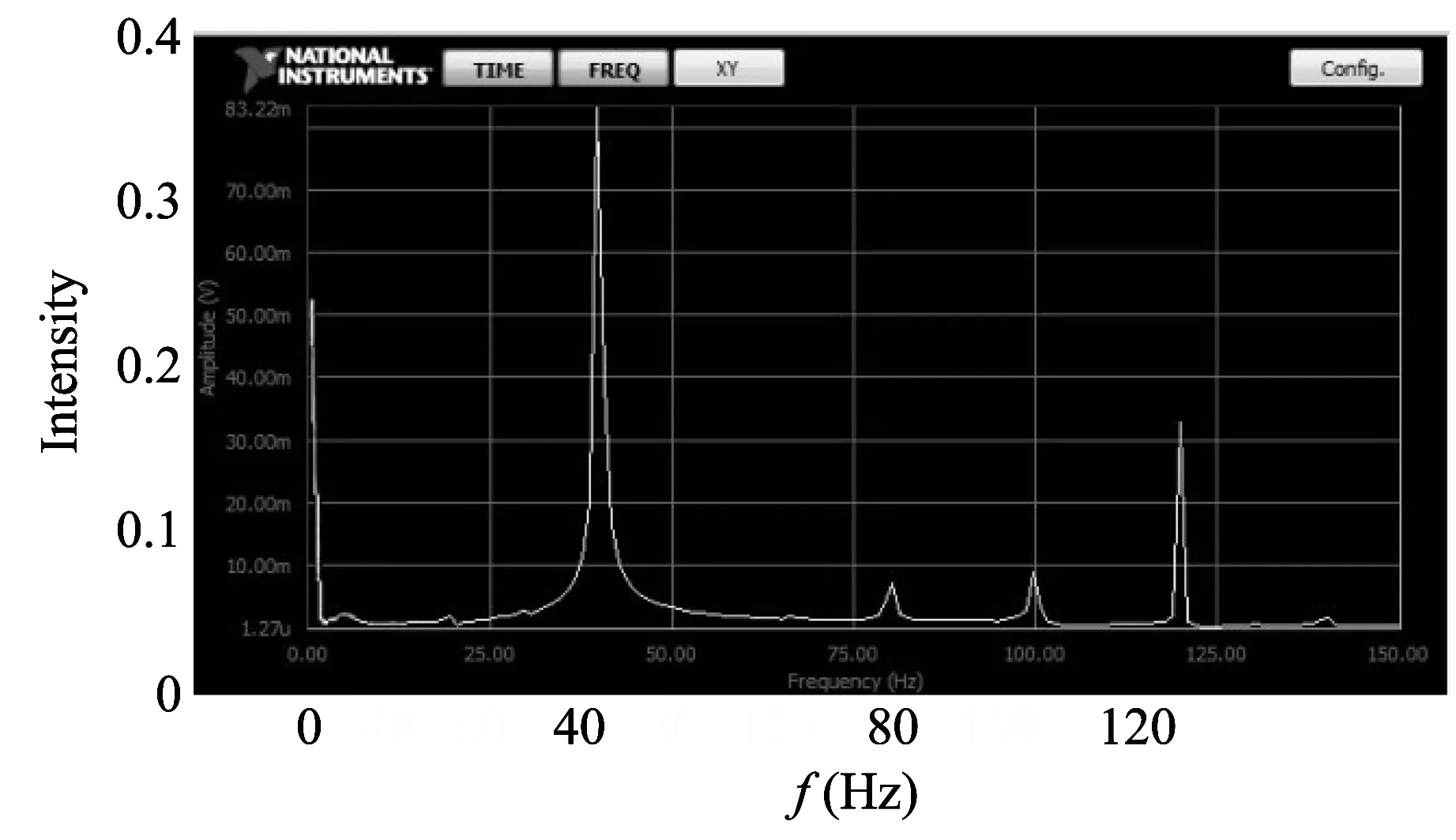
Fig.6 Low-frequency spectrum
5 Conclusion
This paper analyzes the feasibility of measuring polarization based on difference frequency modulation information through three-elastic-optic modulator.It can measure the Stokes vectorS0,S1,S2andS3one time through phase-locked amplification of detection signal.The method measuring polarization just needs to know low detective frequency with 2-3 orders of magnitude smaller than the frequency of the driving signal.The experiment needs neither repeated measurement and rotation nor multiple sets of equipment and simple hardware implementation.It also overcomes the shortcomings of existing method, such as high modulation frequency and invalid collection by using array detector.Through the simulation software measurement and the experimental results, the feasibility of this method is proved.
[1] Winzer P J, Essiambre R.Advanced modulation formats for high-capacity optical transport networks.Journal of Lightwave Technology, 2006, 24(12): 4711-5728.
[2] HU Tian-yi, CUI Sheng.Adcances in the study on polarization mode dispersion monitoring technology.Study on Optical Communications, 2011, 37(6): 1-4.
[3] Weisser S, Raddatz L, Benz A, et al.170 Gbit/s single-polarization transmissions over 650 km SSMF with 130 km spans using RZ-DPSK.In: Proceedings of Optical Fiber Communication Conference (OFC 2005), 2005, 5: 1-3.
[4] LI Yu-bo, ZHOU Qiang, WU Shu-gao, et al.An optical polarization modulator based liquid crystal.Journal of Optoelectronics·Laser, 2006, 17(7): 783-786.
[5] GUAN Wei, Jones G A, LIU Yan-wei, et al.The measurement of the Stokes parameters: A generalized methodology using a dual photoelastic modulator system.Journal of Applied Physics, 2008, 103(4): 043104.
[6] GUAN Wei, Cook P J, Jones G A, et al.Experimental determination of the Stokes parameters using a dual photoelastic modulator system.Applied Optics, 2010, 49(14): 2644-2652.
[7] Diner D J, Davis A, Hancock B, et al.Dual-photoelastic-modulator-based polarimetric imaging concept for aerosol remote sensing.Applied Optics, 2007, 46(35): 8428-8445.
[8] Egan W G.Photometry and polarization in remote sensing.New York: Elsevier, 1985.
[9] Azzam R M A, Bashara N M.Ellipsometry and Polarized Light.Netherlands: North-Holland Publishing Company, 1997.
[10] Van de Hulst H C.Light scattering by small particles.New York: Dover Publications, 1981.
[11] WANG Li-bo, SHI Zhi-dong, YIN Jun, et al.Measurement system of stokes parameters by virtual instrument.Laser & Optoelectronics Progress, 2010, 47(4): 040701.
[12] WANG Yan-tao, JIANG Feng-xian, JIAO Bin-liang.Verification of polarization state using Stokes parameter.Physics Experimentation, 2011, 32(12): 20-23.
基于弹光调制的偏振态测量方法
高婷婷, 韩慧莲
(中北大学 电子测试技术重点实验室, 山西 太原 030051)
摘 要:偏振编码是利用光信号的偏振态承载信息进行编码, 旨在解决高速光纤通信中非线性效应和偏振模色散等问题。 本文提出了基于弹光调制器的偏振态测量方法, 该方法不仅保留了原有弹光调制器偏振测量的优点, 并且克服了现有方法无法用阵列探测器有效采集信息及调制频率高等缺点, 同时给出了Matlab模拟仿真及实验验证方案。 理论分析、 模拟仿真及实验验证了该方法的可行性。 测量结果的误差分析表明, 该方法能满足测量要求, 这为偏振编码在高速光纤通信中的应用创造了条件。
关键词:斯托克斯参量; 差频调制; 偏振测量; 偏振编码
引用格式:GAO Ting-ting, HAN Hui-lian.Polarization state measurement based on photoelastic modulation.Journal of Measurement Science and Instrumentation, 2014, 5(4): 68-73.[doi: 10.3969/j.issn.1674-8042.2014.04.013]
Article ID:1674-8042(2014)04-0068-06
10.3969/j.issn.1674-8042.2014.04.013
Receiveddate: 2014-07-25
Corresponding author:GAO Ting-ting (gaotingting0706@126.com)
杂志排行

Journal of Measurement Science and Instrumentation的其它文章
- Research on measuring time constant of NANMAC thermocouple
- Cutting force measurement based on tool embedded Ni-chrome thin-film micro-sensors
- Empirical model of correction for zenith tropospheric delay
- Detection technique of moving target based on passive millimeter wave
- Mosaic line-scan camera based on FPGA
- Measurement and control system for servo pressure pulse testing equipment