Hardware implementation of adaptive filter for noise cancellation using TMS320C6713
2014-09-07SwatiGodboleSanjayPokle
Swati S Godbole,Sanjay B Pokle
(1.G.H.Raisoni College of Engineering,Rashtrasant Turadoji Maharaj Nagpur University,Nagpur 440016,India; 2.Shree Ramdevbaba College of Engineering and Management,Rashtrasant Turadoji Maharaj Nagpur University,Nagpur 440016,India)
0 Introduction
Adaptive filters are best used in cases where signal conditions or system parameters gradually change and the filter has to be adjusted to compensate for this change.A simple,adjustable but powerful finite impulse response (FIR) filter is the linear adaptive combiner.The least mean square (LMS) algorithm has been implemented to provide the strategy for adjusting the filter coefficients[1].The LMS algorithm is undoubtedly the most popular algorithm for adapting the impulse responseW=[W0,…,WN-1] of an FIR filter so as to minimize the mean square error (MSE) between its output signaly(k) and a desired response signald(k).It updates the filter coefficients according to
e(k)=d(k)-Wk-1u(k),
(1)
Wk=Wk-1+2μe(k)u(k),
(2)
whereu(k) is the input signal vector andμis the adaptation gain or step size.The LMS algorithm is a non-vanishing step size version of a stochastic gradient algorithm.It is popular to a large extent due to its computational similarity.Also,its functioning is quite simple to understand and the algorithm appears to be fairly compatible against implementation errors.
This paper mainly focuses on an important characteristic of an adaptive filter,that is,signal to noise ratio (SNR) in noise cancellation.Speech signal processing applications suffer due to the presence of various types of noises along with the original signal.The objective of this paper is to implement adaptive noise cancellation (ANC) system using digital signal processor (DSP) to remove the undesired noise from a received signal in various audio related applications.
LMS algorithm is used in ANC for its good tracking capabilities and also because it does not require squaring,averaging,or differentiating.It provides an alternative method for determining the optimum filter coefficients without explicitly computing the matrix inversion[1].In addition,the LMS adaptive algorithm is simple in implementation with its highly efficient,desirable and accurate results[2].It has various real-time applications such as communication systems,air conditioning ducts,aircraft,robots,cars,machine tool manufacturing and automations[3].
1 Adaptive noise cancellation
It is observed that in high noise environments,intense background noise often corrupts speech and degrades the performance of many communication systems.Though there are various single channel noise reduction methods like Wiener filtering,Kalman filtering available,dual channel adaptive noise canceller that employs an adaptive filter with the LMS algorithm to cancel the noise component in primary signal picked up by the primary sensor[2]is widely used.The related paper[4]presents an implementation of noise cancellation by using adaptive Wiener filter based on field programmable gate array (FPGA) design and has proved the effectiveness on noise cancellation using an adaptive Wiener filter.Fig.1 shows the block diagram of the ANC system.The basic concept of ANC is to process signal from two sensors and to reduce the level of undesired noise with adaptive filtering techniques.The signal is transmitted over a channel to a sensor that receives the signal in addition to an uncorrelated noisen.The combined signal and noise,d+n,form the “primary input” to the canceller.Another sensor receives a noisen′ which is uncorrelated with the signal but correlated in some unknown way with the noisen.This sensor provides the “reference input” to the canceller.The noisen′ can come from the same source asnbut can be modified by the environment.The noisen′ is filtered to produce an outputythat is a close replica ofn,that is,the adaptive filter’s outputyis adapted to the noisen.
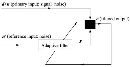
Fig.1 Basic concept of adaptive noise cancellation
Now,the obtained outputyis subtracted from the primary input to produce the system output that would be noise free.Subsequently,the filter output could now be subtracted from the primary input,hence producing an output that would be nothing but the signal alone.
The resulting signal is called an error signale,and it is the output of the system.The resulting error signal would be the desired portion of the primary signal only.This error signal is fed back to the adaptive filter and is used to update the adaptive filter’s coefficients until the overall output becomese=d.When this happens,the adaptation process is finished,and the error signal approaches the desired signald.Hence,the overall output is this error signal and not the adaptive filter’s outputy.Ifdis uncorrelated withn,the strategy is to minimizeE(e2).
Thus,in the system,the reference input is processed by an adaptive filter that automatically adjusts its own impulse response through a least square algorithm like LMS that responds to an error signal dependening on the filters output.Thus,with proper algorithm,the filter can operate under varying conditions and can readjust itself continuously to minimize the error signal.
Assume thatdis uncorrelated withn′ andn,and suppose thatnis correlated withn′.Hence,the output will be
e=d+n′-y.
(3)
Squaring both sides
e2=d2+(n′-y)2+2d(n′-y).
(4)
Taking expectations of both sides of Eq.(4) and realizing thatdis uncorrelated withn′ and withy,it can be got
E[e2]=E[d2]+E[(n′-y)2]+2E[d(n′-y)]=E[d2]+E(n′-y)2].
(5)
The signal powerE[d2] will be unaffected as the filter is adjusted to minimizeE[e2],thus the minimum output power is
Emin[e2]=E[d2]+Emin[(n′-y)2].
(6)
When the filter is adjusted,so thatE[e2] is minimized,E[(n′-y)2] is,therefore,also minimized.The filter outputyis then the best least square estimate of the primary noisen′.In addition,according to Eq.(2),whenE[(n′-y)2] is minimized,E[(e-d)2] is also minimized,that is
e-d=n′-y.
(7)
The outputewill generally contain signals plus some noise.From Eq.(1),the output noise is given byn′-y.Since minimizingE[e2] minimizesE[(n′-y)2],minimizing the total output power minimizes the output noise power and,since the signal in the output is static,minimizing the total output power would result in maximizing the output signal to noise ratio.From Eq.(3),the smallest possible output power isEmin[e2]=E[d2].When this is achievable,E[(n′-y)2]=0.Therefore,y=n′ ande=d.In this case,minimizing output power causes the output signal to be perfectly free of noise[1-2].
2 Implementation of l ms adaptive noise canceller by TMS320-C6713
The implementation of real-time digital signal processing using a general purpose DSP is a very challenging task.Its successful implementation can lead to effective designing of a variety of signal processing algorithms for real world applications[5].
The detailed structure of hardware implementation of the adaptive noise canceller is shown in Fig.2.For effective performance of blind filter,the adaptive filter requires the measurement of reference noise and the primary input signal.The noise can be effectively utilized as a reference only if it is measured in a field where the source is weak.Therefore,the microphone that records the reference noise and the one that records the primary input should be kept at a certain minimum distance.The two speakers,which are used to play the noise,must be the same set in order to synchronize the noise everywhere in the environment set-up[6].
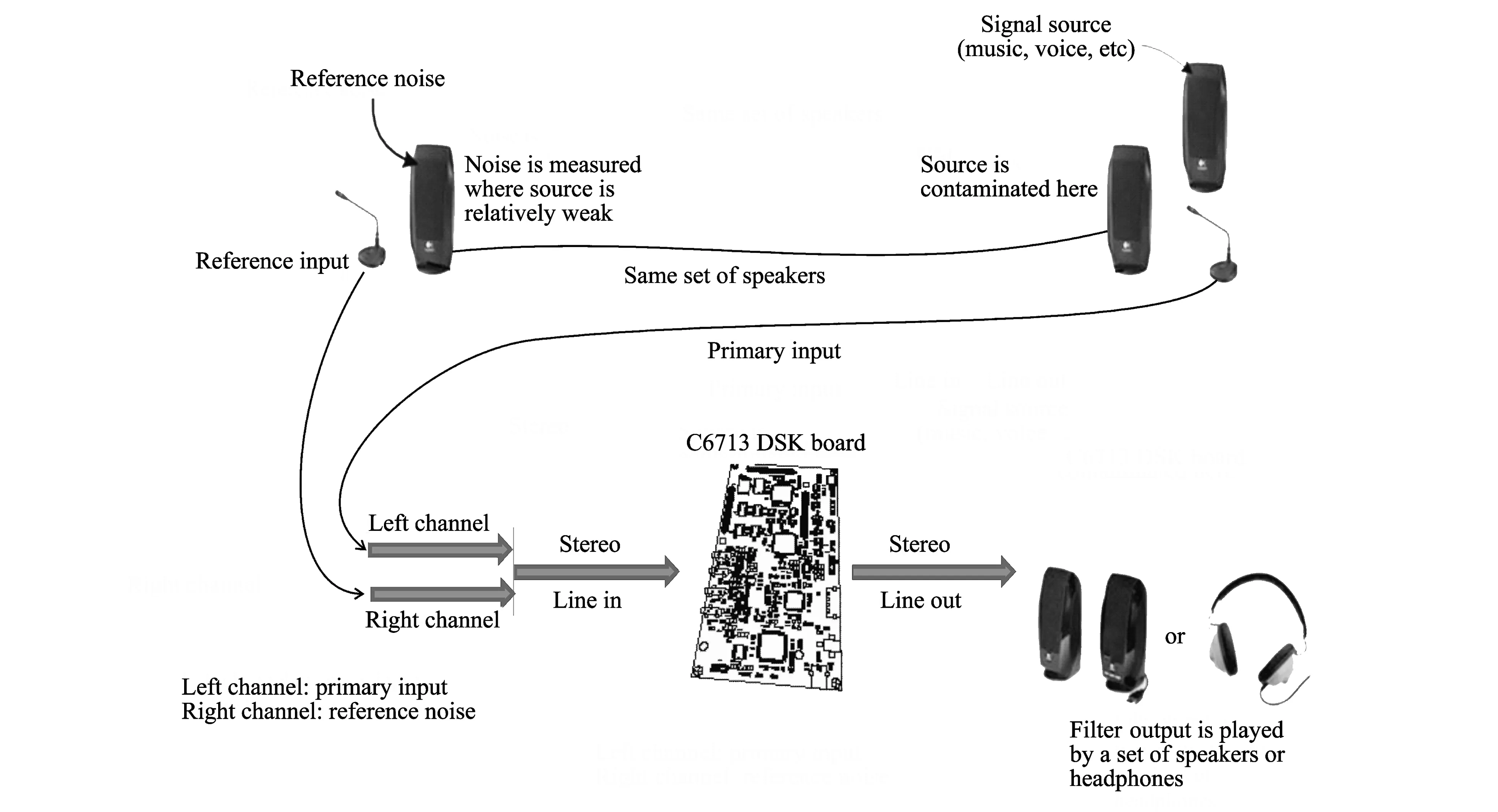
Fig.2 Real-time experimental set-up of ANC system using DSP
The top view block diagram!of the hardware adaptive noise canceller is shown in Fig.3.
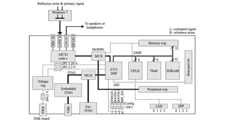
Fig.3 Detailed structure of TMS320C6713 DSK hardware design
The C6713 DSP starter kit (DSK) is a low-cost development platform that supports evaluation as well as development of applications for the TI C6713 DSP family.The stereo line input takes two different signals as its input-the corrupted primary signal in the left channel and the reference noise signal in the right channel.The reference noise,together with the estimated filter output and the step sizemu,determines how fast weights are updated.Similar work is discussed on noise reduction[7]by implementing adaptive filtering algorithms on FPGA chip and demonstrating it through hardware utilization.In Ref.[8] two approaches ase proposed,i.e.hardware implementation of adaptive LMS filter in terms of fixed step size and self correcting adaptive filter (SCAF) architecture on spartan 3XC3S400 FPGA chip,and the performance of both approaches is studied.
2.1 Work carried out
Initial research work is done in Matlab in order to implement ANC system as mentioned in Fig.4.Then adaptive filter is implemented for stationary signals on DSK 6713.The implementation of ANC system for recorded non-stationary signals is carried out on DSK 6713.Furthermore,the successful implementation of real-time ANC system on DSK 6713 DSP is carried out for audio signals.
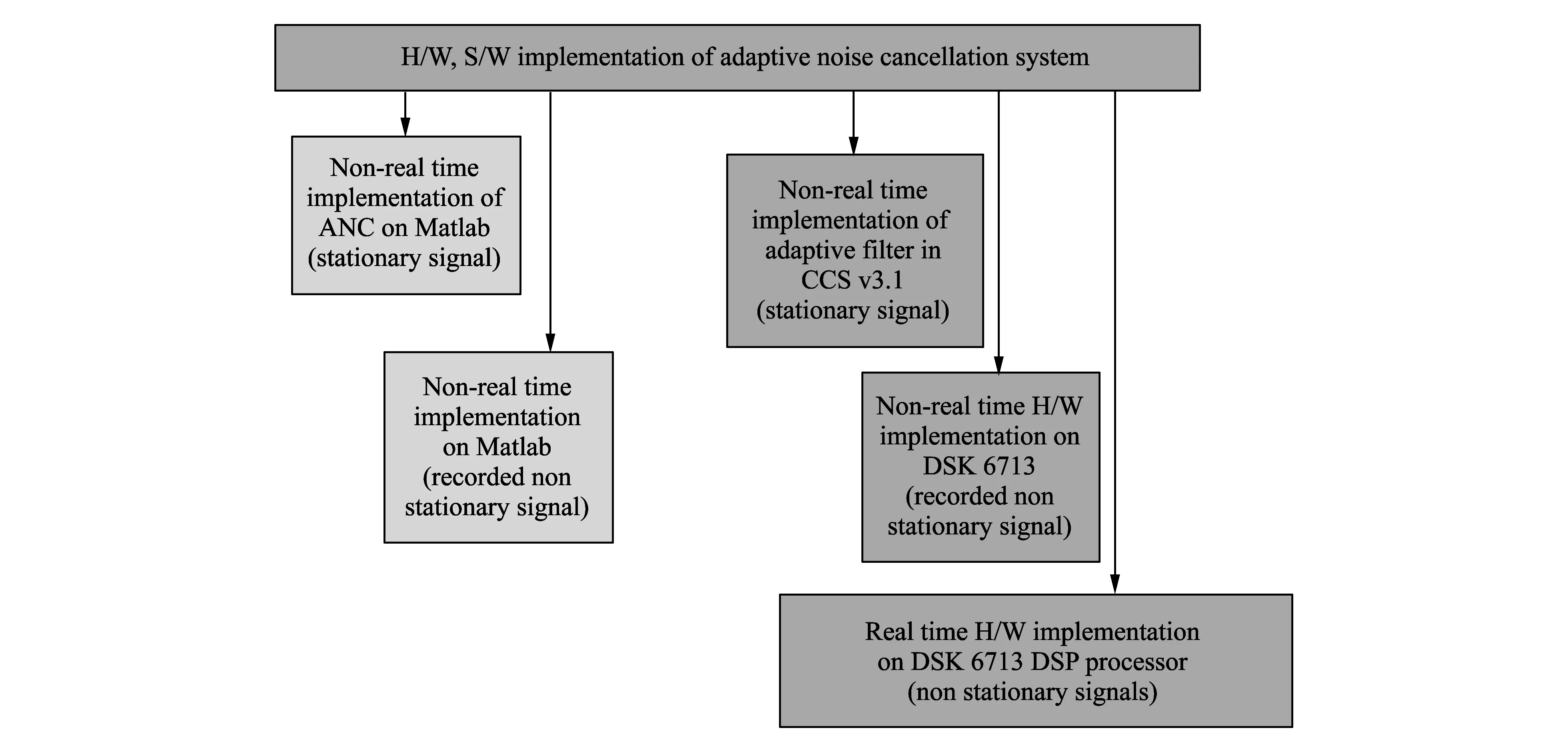
Fig.4 S/W and H/W implementation of ANC system
2.2 Flow chart of ANC system
The flow chart of ANC system is shown in Fig.5.
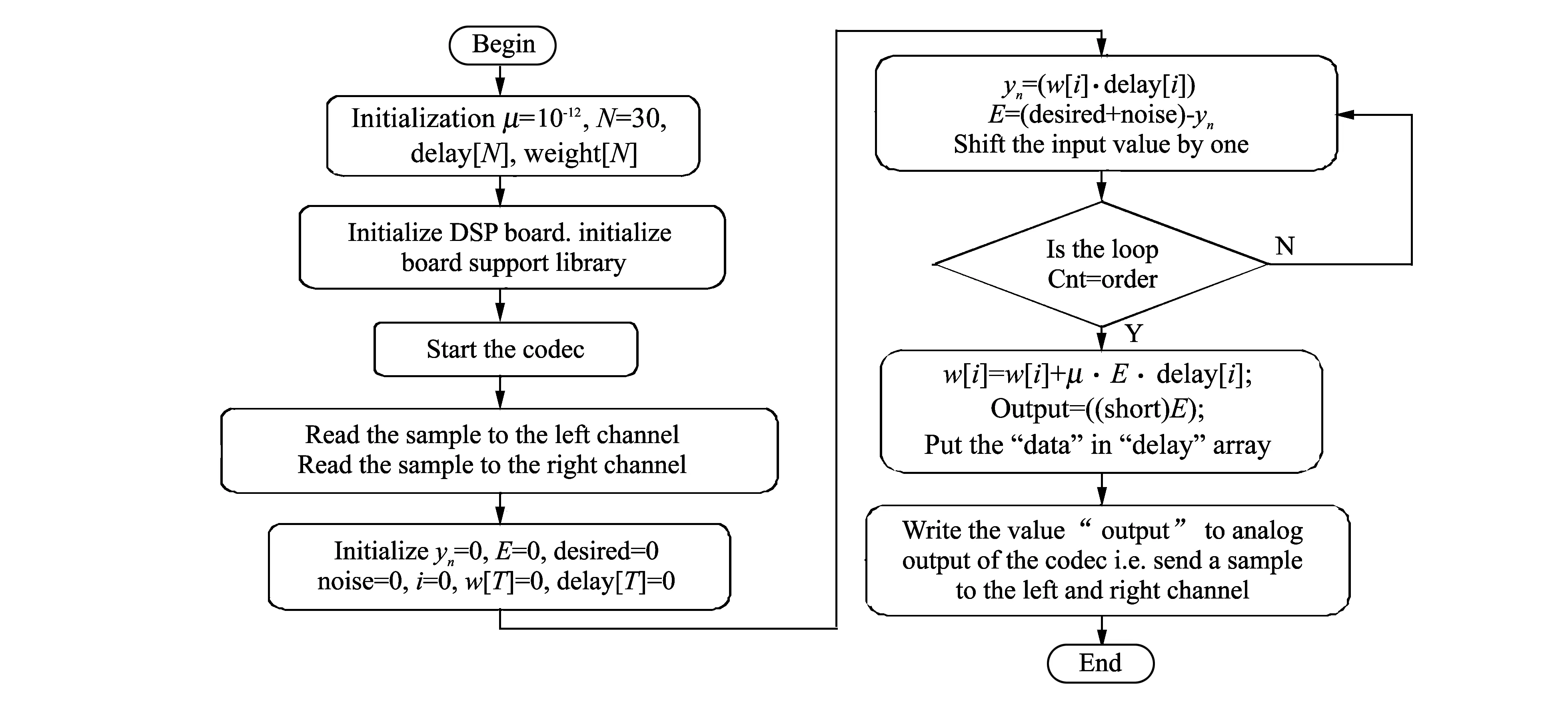
Fig.5 Flow chart of software implementation
Methodology for the adaptation process using the adaptive structure is follows:
1) Determine new samples of the primary signaldand the reference input to the adaptive filter,which represents a noise signal.
2) Calculate the adaptive FIR filter’s outputy,applying Eqs.(1) and 2 with an FIR filter.In the structure of Fig.1,the overall outputeis the same as the desired signald.
3) Calculate the error signal by Eq.(1).
4) Update each coefficient or weight by using Eq.(2).
Again iterate through the adaptive process until the next output is obtained[9-10]
Fig.5 shows a flow chart that implements the adaptive LMS algorithm for the noise cancellation application.The adaptation rate,filter order,and number of samples are considered as 10-12,30,and 60,andFs=44.1 kHz,respectively.The overall output was the adaptive filter’s outputythat adapts to the desired signald.
Figs.6(a) and (b) below show the output of both of the desired speech signal and the undesired interfering signal.Fig.6(c) shows the output,i.e.error signaleafter the adaptation process is converged to the desired signal.All these signals are plotted using code composer studio (CCS).Simulation results show that smaller values of adaptation or convergence rateμlead to slow convergence with better filter coefficients for noise cancellation,whereas higher values ofμgive fast convergence but poor performence for noise cancellation.
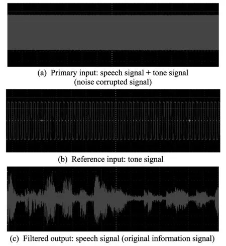
Fig.6 Input/output waveforms
2.3 Methods utilized for experiments
The work is being carried out with three experiments on DSK6713 to examine the capability of the designed ANC system,as given in Fig.7 below.
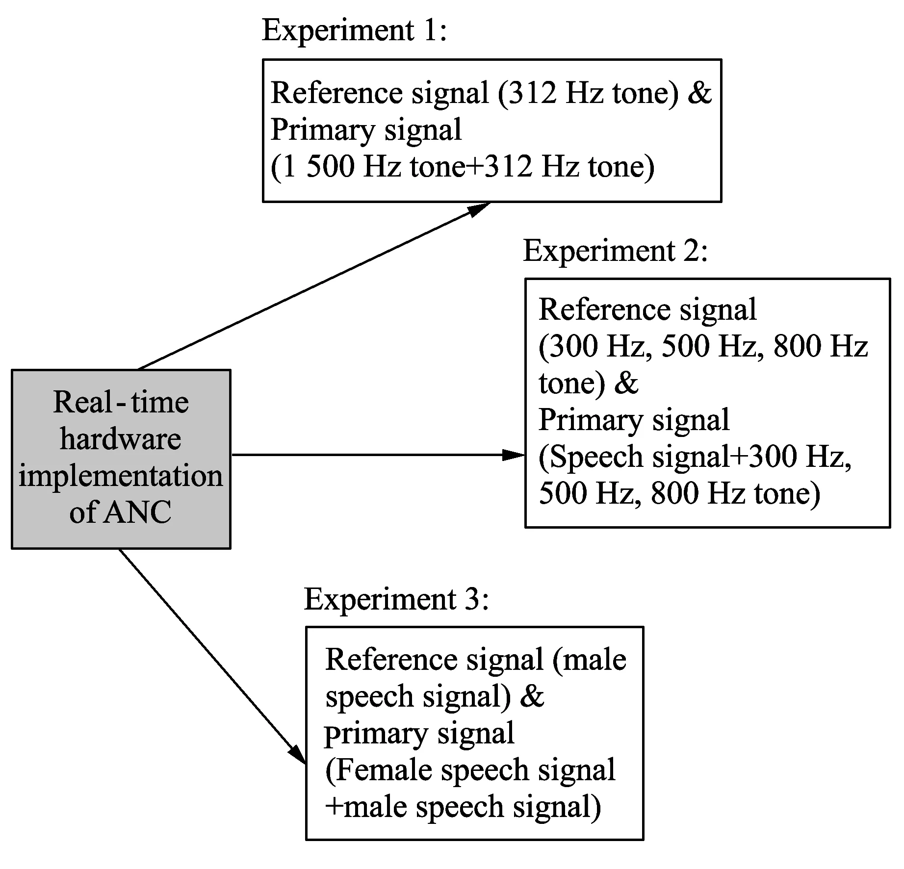
Fig.7 Work carried out on TMS320C6713 DSK
The system is tested with a real-time speech signal with variable frequency.Three types of tests are performed for speech and tone signals to examine the capability of the designed system,as shown in Fig.7.
1) The first test is done on 1 500 Hz of desired sine wave and 312 Hz of noise signal.The undesired 312 Hz sinusoidal signal is being gradually reduced,while the 1 500 Hz desired signal remains as it is.
2) The second test is done on 300 Hz of noise corrupted signals while the other tests are considered for 500 Hz,800 Hz,1 000 Hz and 3 000 Hz of noise corrupted signals with different high noise powers.
3) The third test is done on male speech signal as a reference signal and primary signal is the female speech signal corrupted by male speech signal with variable frequency.
This designed system is tested under various experiments with a wide range of filter parameters.The reduction of acoustic noise in speech has been investigated with gradual improvement in SNR with high accuracy.The following are the various experiments carried out by considering different audio inputs.Several different acoustic signals were successfully implemented to analyze the performance of ANC.
2.3.1 Experiment 1
312 Hz reference signal with 1 500 Hz primary signal
Primary input: 1 500 Hz information signal + 312 Hz tone signal.
Reference input: 312 Hz tone signal.
Filtered output: 1 500 Hz information signal.
2.3.2 Experiment 2
300 Hz reference tone signal with primary speech signal:
Primary input: speech signal + tone signal.
Reference input: tone signal.
Filtered output: speech signal.
500 Hz reference tone signal with primary speech signal:
Primary input: speech signal + tone signal.
Reference input: tone signal.
Filtered output: speech signal.
800 Hz reference tone signal with primary speech signal:
Primary input: speech signal + tone signal.
Reference input: tone signal.
Filtered output: speech signal.
2.3.3 Experiment 3
Reference male speech signal with primary female speech signal:
Primary input: female speech signal + male speech signal.
Reference input: male speech signal.
Filtered output: female speech signal.
2.4 Experimental set-up
The experimental set-up in Fig.8 shows the two WAV files that were used to generate the desired speech signald,the noise signaln,the primary input signal,i.e.d+n,and the reference input signaln′.
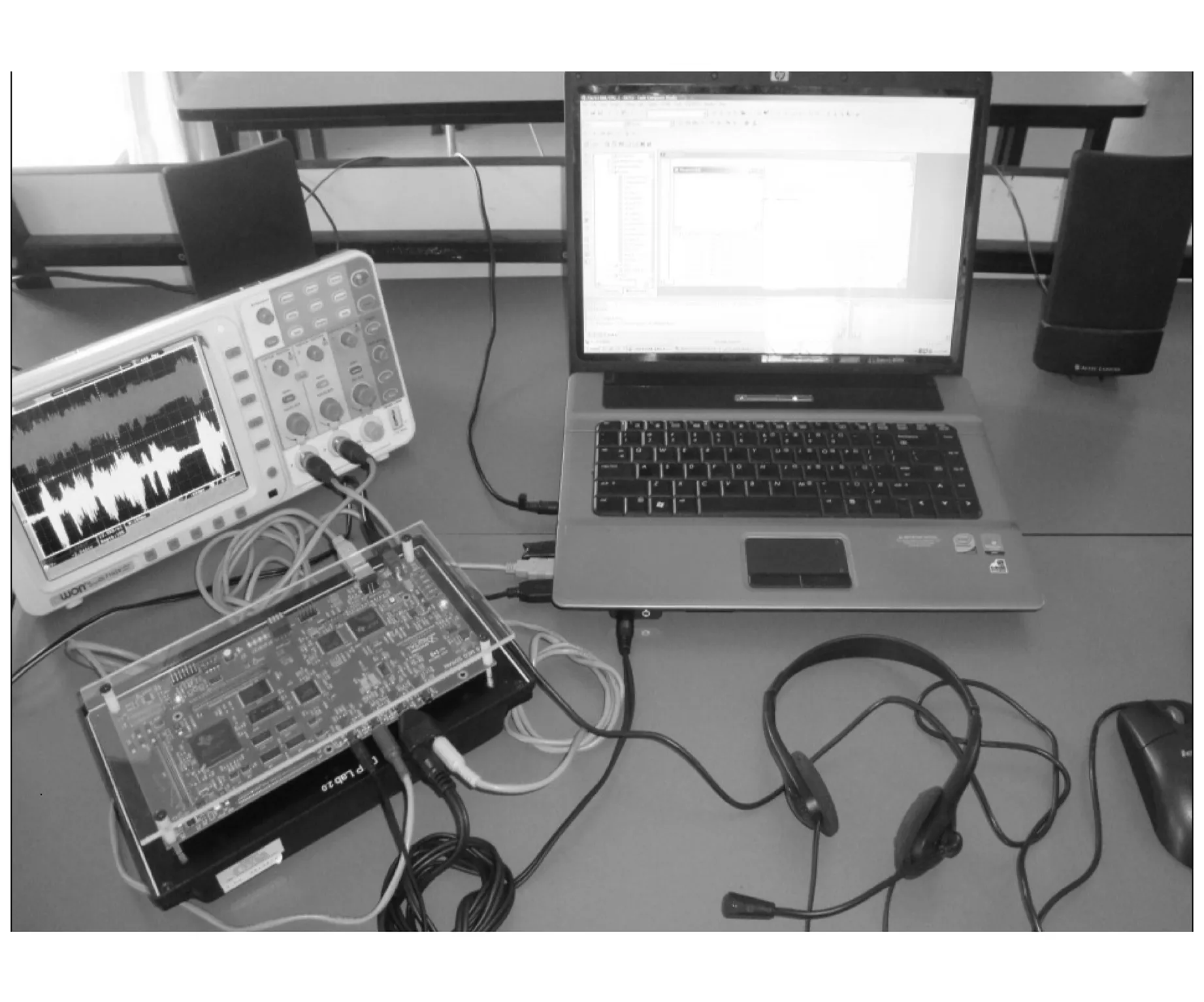
Fig.8 Hardware testing system and results for the proposed adaptive noise canceller
The primary signal is generated (the desired speech signal is contaminated with the noise signal).These input signals are then fed into the DSK line_in,a stereo jack,the primary signal into the left channel and reference signal into the right channel.Table 1 shows the analysis of the proposed parameters for effective noise cancellation.The optimal parameters,considered for effective implementation of ANC on DSK are the length of the filter taken to be 30 taps (M=30).The sampling frequency is taken to be 44.1 kHz while the convergence factor used for the LMS algorithm is 10-12.Thus,various parameters considered for effective noise cancellation were successfully tested as per the proposed design[11].
Table1Analysisoftheproposedparametersandtheirperformance

No.ParametersUsed value1Order of filter302Sampling rate44.1 kHz3Convergence factor10-12
3 Experimental results
3.1 Experiment 1
Desired: 1 500 Hz tone signal
Undesired: 312 Hz tone signal
A desired tone signal of 1 500 Hz with an additive undesired tone signal of 312 Hz forms one of the two inputs to the adaptive filter structure.A reference tone signal,with a frequency of 312 Hz,is the input to a 30-coefficient adaptive FIR filter.The 312 Hz reference tone signal is correlated with the 312 Hz additive undesired tone signal but not with the 1 500 Hz desired signal.At each sampling instant,the output of the adaptive FIR filter is calculated and the 30 weights or coefficients are updated along with the delay samples.The error signaleis the overall desired output of the adaptive structure.This error signal is the difference between the desired signal and additive noise,d+n,and the adaptive filter output,yn.Various external inputs that are used in this example are
1) Primary input: sine (1 500 Hz) + sine (312 Hz) (from left channel);
2) Reference input: sine (312 Hz) (from right channel).
3.1.1 Implementation of the adaptive filter noise canceller in CCS
The adaptive noise canceller is implemented in C language as it provides excellent opportunity for a quick and professional way to study the whole operation of the system.The results are verified and the following outputs are obtained,as shown in Fig.9.
In Fig.9,the undesired 312 Hz sine signal is being reduced gradually,while the desired 1 500 Hz signal remains unchanged.The output desired is the error signale,which is converged to the desired signal.The faster rate of cancellation is observed with a larger value ofμ.And ifμis too large,the adaptation becomes unstable and therefore needs to be optimized.The output waveforms of the system are plotted in Fig.9.
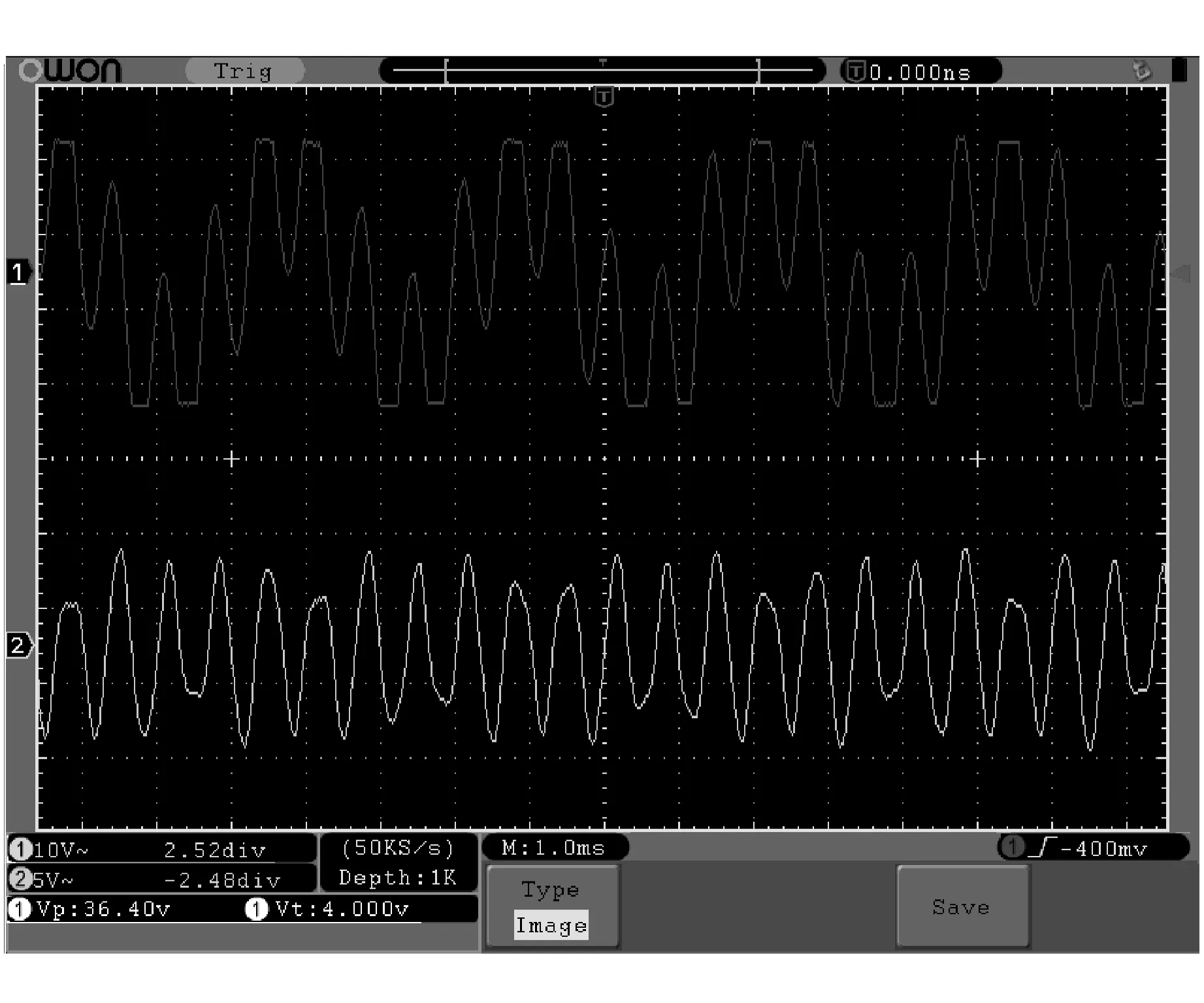
Fig.9 Filtered tone signal at low noise (① Filtered signal; ② Primary input signal)
3.1.2 SNR analysis
When the designed system is tested with sinusoidal tone signal as shown above,it shows SNR improvement of 7 dB at 312 Hz of noise,as shown in Table 2.The ANC system performance is further tested by making variations in the amplitude and frequency of the undesired input tone signal in experiment 2 that reflects improved SNR of the system[12].
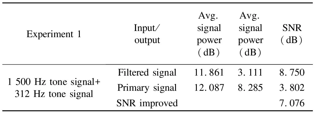
Table 2 SNR analysis
3.2 Experiment 2: adaptive FIR filter for noise cancellation using desired signal as a speech signal
The second experiment extends the previous one to cancel undesired sinusoidal tone signal while using desired signal as a speech signal.The 16-bit desired signal is input through the left channel and the undesired 16-bit noise signal through the right channel.
Desired: Speech signal (Shree Gajanan Vijay Granth,Adhyaya 10 (it is in a female’s voice))
Undesired: 300 Hz,500 Hz,800 Hz,1 000 Hz,3 000 Hz of tone signal
A desired speech signal with a variable frequency,contaminated with the above-mentioned noise into the left channel and an undesired sinusoidal noise signal of 300 Hz into the right channel is provided as input.After the implementation of program,it is observed that the 300 Hz of noise signal gets reduced gradually.The frequency of input sinusoidal external tone interference gets slightly increased from 500 Hz to 3 000 Hz to test the proposed system.It is observed that the performance of ANC system improves by adjusting optimal value ofμ.The Figs.10,11,12,13 and 14 shown suggest the output spectrum of the error signaleafter the adaptation process when converged to the desired signal.
In Fig.10,primary input: desired speech signal + 300 Hz undesired tone signal; reference input: 300 Hz undesired tone signal.
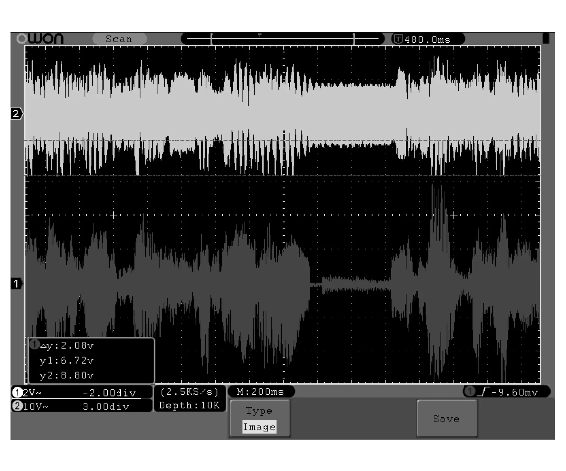
Fig.10 Filtered tone signal at 300 Hz of noise (① Filtered signal; ② Primary input signal)
In Fig.11,primary input: desired speech signal + 500 Hz undesired tone signal; reference input: 500 Hz undesired tone signal.
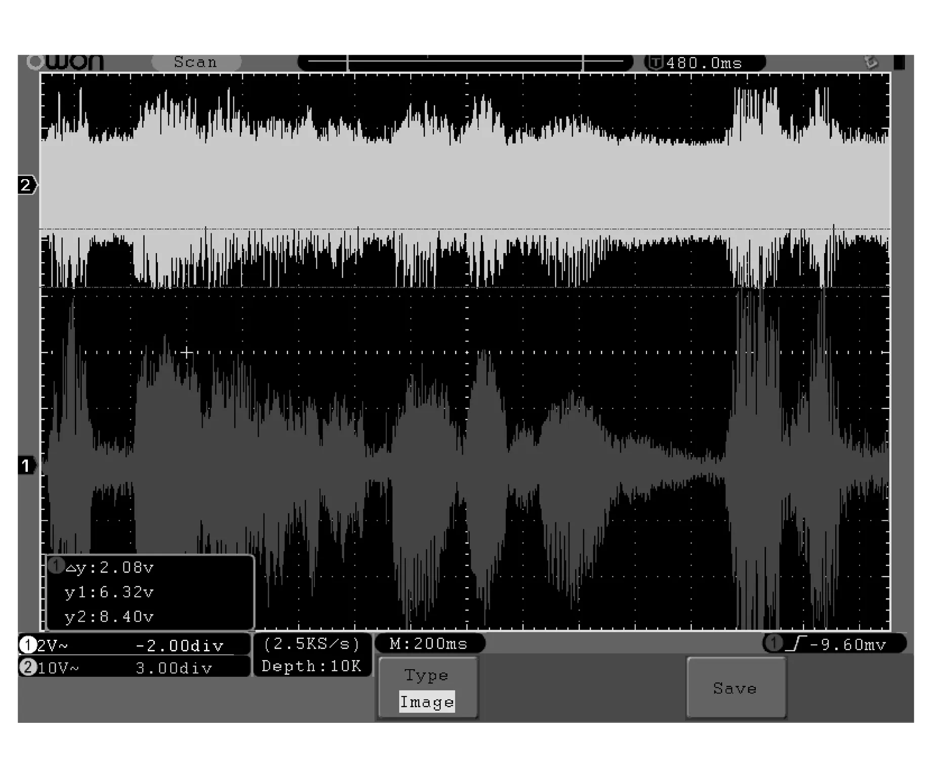
Fig.11 Filtered tone signal at 500 Hz of noise (① Filtered signal; ② Primary input signal)
In Fig.12,primary input: desired speech signal + 800 Hz undesired tone signal; reference input: 800Hz undesired tone signal.
In Fig.13,primary input: desired speech signal + 1 000 Hz undesired tone signal; reference input: 1 000 Hz undesired tone signal.
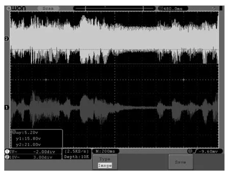
Fig.12 Filtered tone signal at 800 Hz of noise (① Filtered signal; ② Primary input signal)
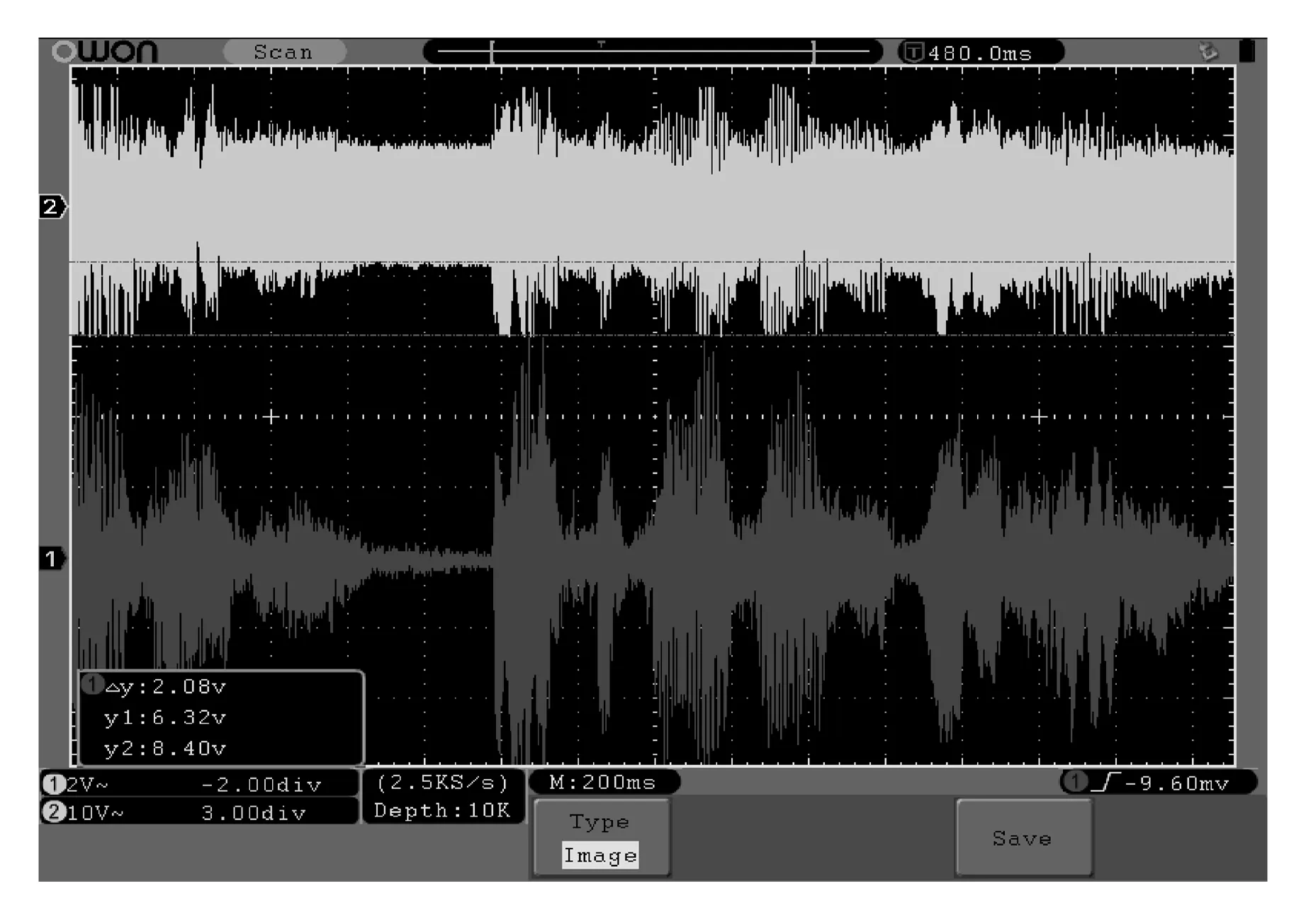
Fig.13 Filtered tone signal at 1 000 Hz of noise (① Filtered signal; ② Primary input signal)
In Fig.14,primary input: desired speech signal + 3 000 Hz undesired tone signal; reference input: 3 000 Hz undesired tone signal.
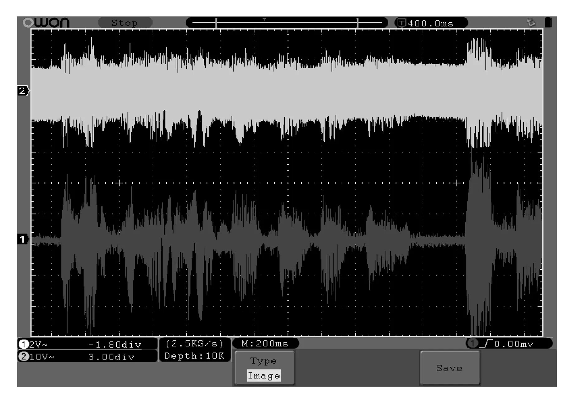
Fig.14 Filtered tone signal at 3 000 Hz of noise (① Filtered signal; ② Primary input signal)
The obtained results shown in Table 3 are indication of successful and effective performance for the system vis-a-vis SNR.
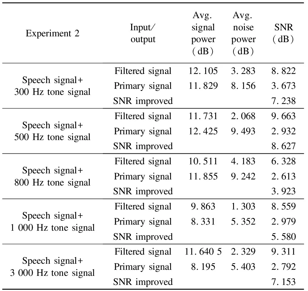
Table 3 SNR analysis
3.3 Experiment 3
Desired: female speech signal (Shree Gajanan Vijay Granth,Adhyaya No.10 (in a female’s voice))
Undesired: male speech signal (Shree Gajanan Vijay Granth,Adhyaya No.11 (in a male’s voice))
The third experiment suggests the primary signal,i.e.female speech signal,as the desired signal contaminated with the male speech signal given to the left input channel and the reference signal,i.e.undesired male speech signal,to the right input channel.On implementation of ANC system,it is observed that the output error signaleconverged to the desired female speech signal,depicting the male speech signal being cancelled gradually,as shown in Table 4.
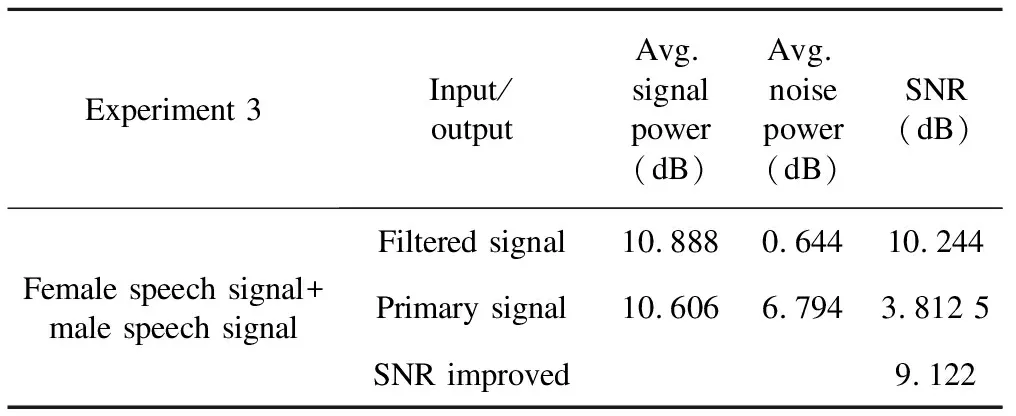
Table 4 SNR analysis
Fig.15 shows the primary signal (female+male speech signal) and the desired filtered output (female speech signal) after the adaptation process.
Thus,the system is tested for different sound signals.The three different experiments are implemented and respective results are presented.The obtained original and recovered signal remain unchanged.The input and output SNR was measured by taking optimal parameters for analysis and is shown in Tables 2,3 and 4.Simulations and real-time hardware implementation results show that both implementations are most accurate.
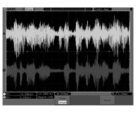
Fig.15 Experimental results: ① Filtered female speech signal; ② Incoming primary signal
4 Conclusion
Using the LMS algorithm,which can effectively perform real-time noise reduction without prior knowledge of noise statistics,adaptive noise canceller has been implemented on TI TMS320C6713 DSK board successfully.The real-time processor results are analyzed for two types of reference signals,tone signal and male speech signal,with different frequecies.These signals are tested and judged with the help of digital storage oscilloscope and the filter performance is measured in terms of SNR improvement.Thus,noise canceller could filter out tone signal and male speech signal effectively in real time.
Speech signal is analyzed at various frequencies and voltage levels to check the effect of noise filtering and observed that the effect of noise gets more prominent when the frequency of noise and speech signal is highly correlated or noise signal has higher amplitudes.
It is observed that the voice signal can still be recovered perfectly.It requires perfect filter order andμvalue and thus we get the steady-state performance accordingly.Therefore,it can be concluded that as the step size value increases within the stability region,convergence speed and the misadjust-ment will also increase.And as the step size value decreases,the convergence time will increase and the misadjustments will reduce.However,if we increase the filter order value,the convergence time and the misadjustments will also increase.
In low and medium power noises,the system showed SNR improvement up to 7 dB and at high power noise test,5 dB of SNR improvement.Based on these results using the designed model in TMS320C6713 DSP system,LMS algorithm of adaptive noise canceller can effectively resolve the problem of eliminating unwanted noise from a desired signal such as speech signal or any other type of audio signal and prove to be successful.
[1] Haykin S O.Adaptive filter theory.Upper Saddle River: Prentice Hall,2002.
[2] Widrow B,Glover J R,McCool J M,et al.Adaptive noise cancelling: principles and applications.In: Proceedings of the IEEE,1975,63(12): 1692-1716.
[3] Rosado-Mu†oz A,Bataller-Mompeán M,Soria-Olivas E,et al.FPGA implementation of an adaptive filter robust to impulsive noise: two approaches.IEEE Transactions on Industrial Electronics,2011,58(3): 860-870.
[4] Jheng H Y,Chen Y H,Ruan S J,et al.FPGA implementation of high sampling rate in-car non-stationary noise cancellation based on adaptive Wiener filter.In: Proceedings of 2011 IEEE/IFIP 19th International Conference on VLSI and System-on-Chip (VLSI-SoC),Hong Kong,2011: 114-117.
[5] Texas Instruments,Inc.Code composer studio user’s guide,No.SPRU32,1999.
[6] Texas Instruments,Inc.Code composer studio quick start guide,No.SPRU368A,1999.
[7] Martínez M E I.Implementation of QRD-RLS algorithm on FPGA∥Application to noise canceller system.IEEE Latin America Transactions,2011,9(4): 458-462.
[8] Nekouei F,Zargar-Talebi N,Kavian Y S,et al.FPGA implementation of LMS self correcting adaptive filter (SCAF) and hardware analysis.In: Proceedings of the 8th IEEE,IET International Symposium on Communication Systems,Networks and Digital Signal Processing,Poznan,2012: 1-5.
[9] EdGate Technologies.TMS320C6713 DSK user manual.[2014-03-11].http:∥c6000.spectrumdigital.com/dsk6713/V2/docs/dsk6713_TechRef.pdf.
[10] TMS320C6713x DSP library programmer’s reference.[2014-03-21].http:∥www.s3.kth.se/signal/project_course/2005/yellow/.../TI.../spru657.pdf
[11] Wallace R B,Goubranand R A.Noise cancellation using parallel adaptive filters.IEEE Transactions on Circuits and Systems-11: Analog and Digital Signal Processing,1992,39(4): 239-243.
[12] Mollaei Y.Hardware implementation of adaptive filters.In: Proceedings of 2009 Student Conference on Research and Development (SCOReD),UPM Serdang,Malaysia,2009: 45-48.
杂志排行
Journal of Measurement Science and Instrumentation的其它文章
- Numerical simulation of projectiles with different structures penetrating multi-storey concrete target board
- A new measuring technique in detecting of high voltage three phase induction motor for single phasing
- Error modeling of 3-RSR parallel robot based on D-H transformation matrix
- Signal de-noising method based on wavelet decomposition
