Palaeogeography, palaeohydraulics and palaeoclimate of the Mio-Pliocene Siwalik Group, eastern India
2014-08-28SunipaMandalSubirSarkarNiveditaChakrabortyPradipBose
Sunipa Mandal , Subir Sarkar, Nivedita Chakraborty, Pradip K. Bose
1. Department of Geology, Asutosh College, Kolkata 700026, India
2. Department of Geological Sciences, Jadavpur University, Kolkata 700032, India
Abstract South-southwestward palaeocurrent swerved to east-southeast and then broadly to southeast over the transition from alluvial fan to axial channel and then to the flood plain in the Mio-Pliocene foreland system within which the Siwalik Group depositd in Darjeeling-Jalpaiguri Districts, eastern India. Palaeocurrent pattern is found to be multi-modal on the fans, virtually unimodal on the axial channel zone and again multi-modal, more profoundly,on the flood plain. Coarse siliciclastic mass-flows were progressively eliminated and gave way to predominant bed-load transport downfan and the axial river, and then to suspensionload dominance in fine siliciclastics on the flood plain. Distal flood plain lacustrine sediment included most of the coals and the entire bulk of the dolomitic limestone. Further resolution in palaeogeography within the frame of aforementioned foursome facies associations is elicited in twenty-six distinctive facies altogether.
Key words Mio-Pliocene Siwalik Group, Darjeeling Himalayas, spatial variation, axial river reconstruction, vegetation
1 Introduction*
Sedimentological account of the almost exclusively siliciclastic Siwalik Group deposited in the Darjeeling Himalayas, North Bengal, India is too meagre to achieve high-resolution process-product relationship in sedimentation (Figure 1; Banerjee and Banerjee, 1982; Acharyya,1994). Broad stratigraphic classification and the corresponding palaeogeographic interpretations of the Siwalik Group have been borrowed from work done in the western Himalayas where exposures are much better in quality because of the relative aridity (Pilgrim, 1919; Parkash et al.,1980; Kumar and Tandon, 1985; Tokuoka et al., 1986; Wa-heed and Wells, 1990; Burbank and Beck, 1991; Khan et al., 1997; Zaleha, 1997; DeCelles et al., 1998; Nakayama and Ulak, 1999; Brozovic and Burbank., 2000; Sharma et al., 2001; Ulak and Nakayama, 2001; Thomas et al., 2002;Garzione et al., 2003; Kumar et al., 2003a, 2003b; Kumar et al., 2004; Ulak, 2005; Szulc et al., 2006; Kumar et al.,2007; Sinha et al., 2007; Shah et al., 2009; Shukla et al.,2009; Ullah et al., 2009; Khan and Tewari, 2011; Sigdel et al., 2011). This paper intends to improve the sedimentological insight about the Siwalik Group in the frame of a foreland where its deposition took place (Acharyya, 1976,1994; Raina, 1976; Tandon, 1991; Willis, 1993; Burbank et al.,1996; DeCelles et al., 2000, 2001; Lave and Avouoc,2000; Mukul, 2000; Najman and Garzanti, 2000; Richards et al., 2006; Robinson et al., 2006; Yin, 2006; Mitra et al., 2010; Long et al., 2011; Ray and Neogi, 2011). The exposures are in inferior quality, notwithstanding the present study recognizes a large number of distinctive facies,which can be grouped in four associations. While the facies reflect the sedimentation dynamics, the associations relate to palaeogeography. Palaeohydraulic parameters have also been estimated from the sandstones deposited within the main river channel system of the Siwaliks. To overcome the limited extent of sections, facies logs have been erected in 75 locations. Palaeocurrent patterns and directions are determined separately for each of the associations. Oxide and elementary siliciclastic rock chemical features offer significant insight about contemporary palaeoclimate; δ13C and δ18O values of carbonates allow further revalidation or refinement. Results of similar analyses carried out at different locales all along the 2000 km-long of the Himalayan belt, while taken together, offer an opportunity to delve into the significance of spatial variations that may exist.
2 Geological background
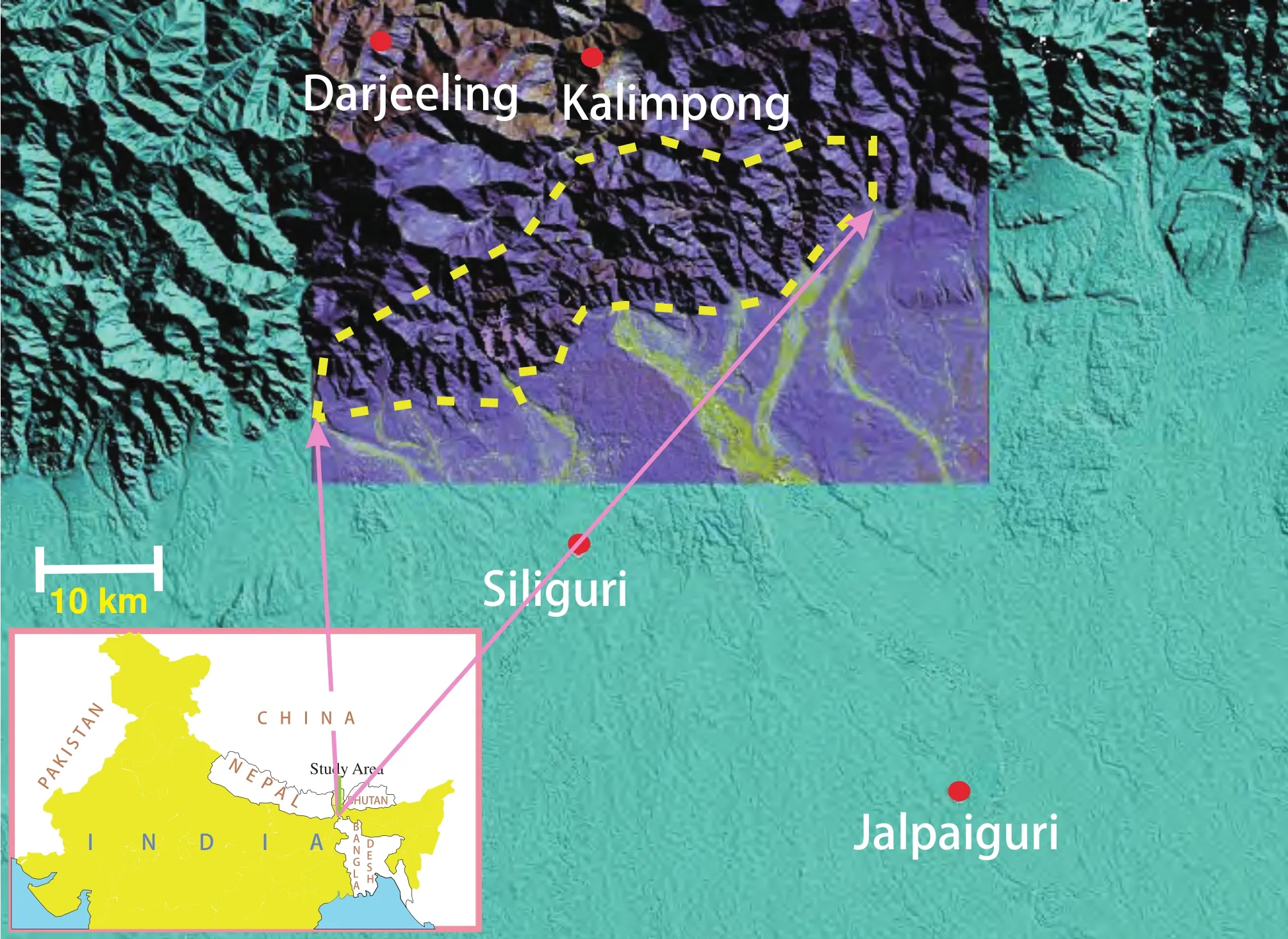
Figure 1 Study area demarcated on LISS-III image superimposed on SRTM DEM in the foothills of eastern Himalayas.
The predominantly siliciclastic Siwalik Group was deposited in a Mio-Pliocene foreland system in the Himalayas (Johnson et al., 1985; Gautam and Appel, 1994; Meigs et al., 1995; DeCelles et al., 1998; Najman et al., 2001;Sangode et al., 2003). Along the roughly east-west aligned Himalayan foothills, the 2000 km-long exposure belt of the Siwalik Group is almost continuous. In the eastern part of India where this work has been carried out the Siwalik exposure belt of 100 km long is bounded on the south by the Quaternary cover and on the north successively by the Permo-Carboniferous Gondwanas, Proterozoic metasedimentary Daling and Buxa Group of rocks, and then further north by high-grade central crystalline from Pleistocene going back to the Palaeoproterozoic (Raina, 1976;DeCelles et al., 1998, 2000, 2001; Watts et al., 2005;Schopf et al., 2008; Bhattacharyya and Mitra, 2009; Mitra et al., 2010; Long et al., 2011; Ray and Neogi, 2011).The belt is bounded by thrust planes, viz., MFT on south and MBT on north. The vergence of all the thrust planes in the region is southward; consequently general dip direction of all the sedimentation units is northward. The Siwalik stratigraphy traditionally bears a tripartite classification: within India, Lower, Middle and Upper in the rank of formations/subgroups (Pascoe, 1950; Acharyya,1976, 1994; Mitra et al., 2010), although their structural sequence, in general, evinces position-reshuffling between the formations because of post-depositional thrusts (Mitra et al., 2010 and references therein). Regarding palaeogeography of deposition, the general consensus is that the conglomerate-rich Upper Siwalik had an alluvial fan origin; the sandstone-dominated Middle Siwalik belonged to fluvial channels and the mud-enriched Lower Siwalik was deposited on river flood plain, accommodating carbonates in patches (Acharyya, 1994). It is imperative that the three formations constituting the Siwalik Group are coeval and the Group, as a whole, is a product of overall progradation(Parkash et al., 1980; Banerjee and Banerjee, 1982; Kumar and Tandon, 1985; Acharyya, 1994; DeCelles et al., 1998;Brozovic and Burbank, 2000). Local gradational contacts observed in upward transitions from the Middle to Upper Siwalik within the study area and from the Lower to Middle elsewhere (Johnson et al., 1985; DeCelles et al., 1998;Sangode et al., 2003) further testify this contention.
3 Facies
Four distinctive associations of facies identified in the study area, are named as alluvial fan, main channel, flood plain and lacustrine (Figures 2, 3a, 3b). While the former two correspond to the Upper and Middle Siwalik, the latter pair comprises the Lower Siwalik, locally named as the Chunabati Formation (cf. Acharyya, 1994). Details about these associations are as follows.
3.1 Alluvial fan association
Conglomerate is an important constituent and the rest is sandstone, often pebbly, in this association. The followings are the facies that comprise it:
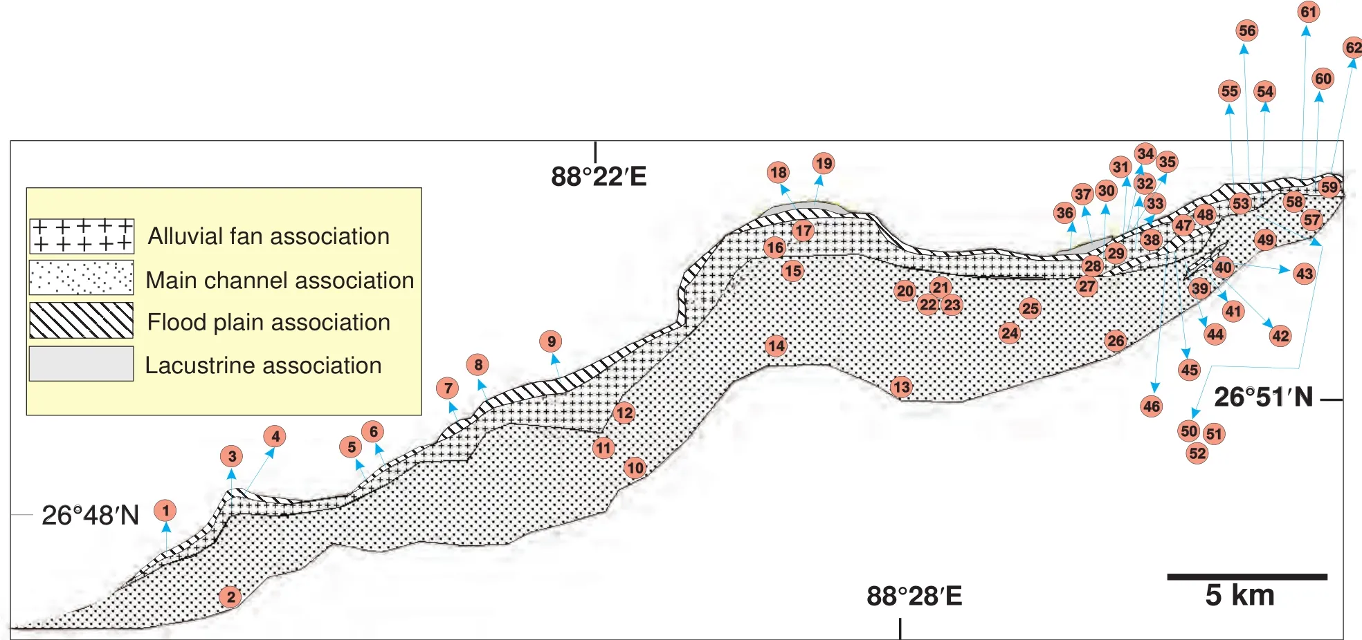
Figure 2 Facies association map of the Siwalik Group in the study area. The russet dots are the location of the sections detailed below.
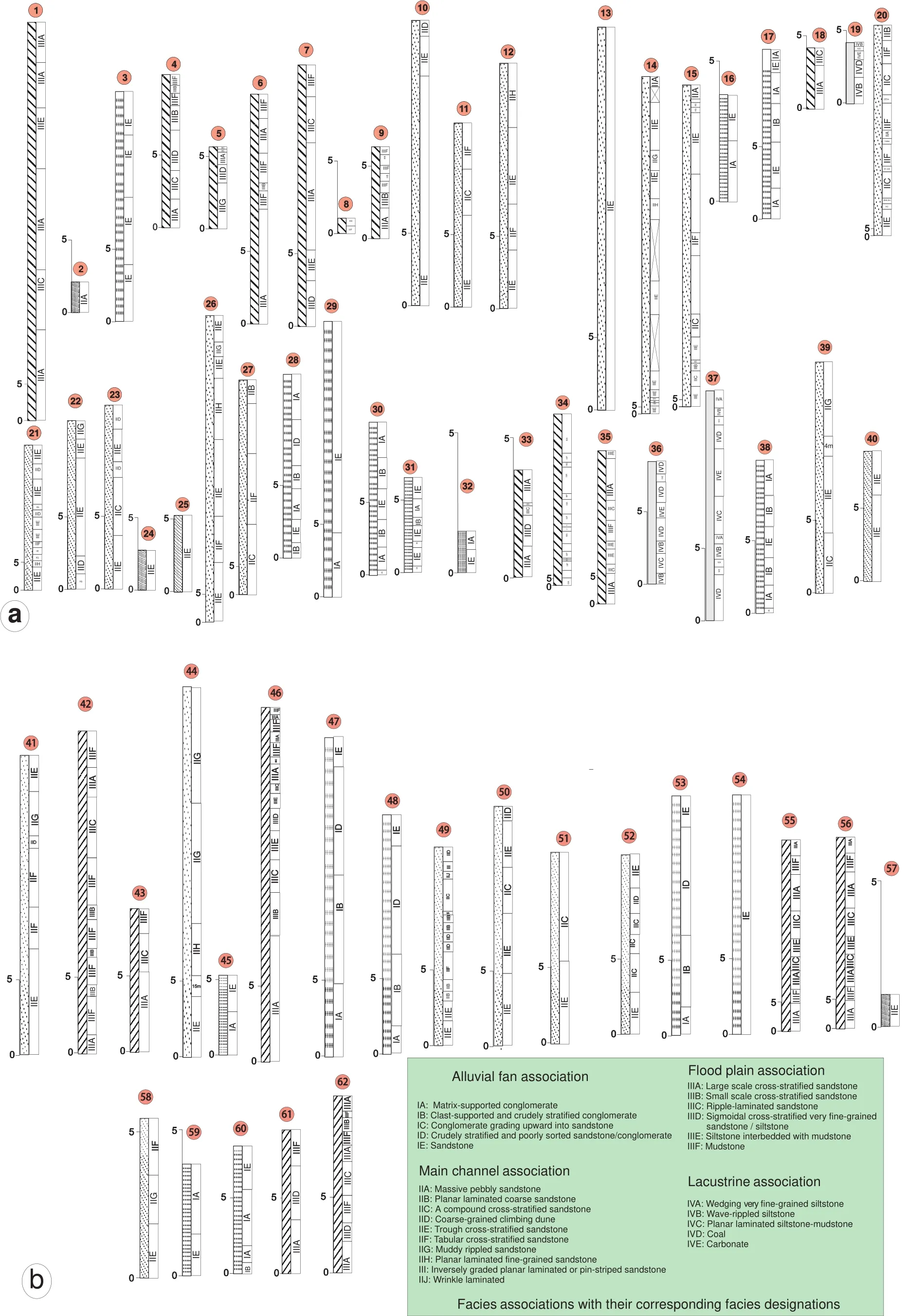
Figure 3 Measured logs depicting vertical successions of facies and their associations at different locations in the study area: Western sector (a) and eastern sector (b). For the facies association symbols and section locations (numbered above) see Figure 2.
Matrix-supported conglomerate facies (IA)devoid of current structures is generally massive, but may have reverse grading on rare instances (Figure 4a). Its body geometry is lenticular, generally having flat base and convex top (Figure 4b), but some having concave-up channel-form too (Figure 4c). In this matrix-supported conglomerate the grain-size distribution is broadly bimodal, but both the pebble and sand fractions are poorly sorted. The clasts are randomly distributed and oriented, some standing almost vertical. The maximum thickness and outcrop width of the facies encountered are respectively 3.9 m and 19 m.The maximum clast-size averaging from ten largest ones in each outcrop varies between 55-6 cm.
Clast-supported and crudely stratified conglomerate facies (IB)has its constituent clasts generally smaller, not exceeding 15 cm in length and is better sorted in comparison to those of the preceding facies. The clasts are dominantly aligned parallel to bedding and may even show short-axis imbrications. They generally have smooth rounded ages. The facies has tabular body geometry, and both top and bottom are sharp. The maximum thickness and exposure width encountered are 1.8 m and 12 m respectively (Figures 4d, 4e).
Conglomerate grading upward into sandstone facies (IC)has clast-size intermediate with reference to the preceding two facies, not exceeding 14 cm on the higher side and sparingly smaller than 2 cm on the lower side. Its texture is generally matrix-supported, but concentration of pebbles greater at the bottom of the beds effecting a coarsetail frequency grading (Figure 4f). The top part of the beds is almost entirely sandy within which faint cross-strata are often discernible. The facies bodies have flat bases, but slightly convex upward tops. The maximum thickness and exposure width recorded are 6 m and 30 m respectively.
Crudely stratified and poorly sorted pebbly sandstone/conglomerate facies (ID)may, at places, bear faint crossstrata and have small (< 4.7 cm) rounded pebbles randomly scattered within poorly sorted coarse sandstone. Base of this facies is flat and top convex upward. The maximum thickness and outcrop width recorded are 50 cm and 5 m respectively.
Sandstone facies (IE), coarse-grained and poorly sorted,is commonly trough cross-stratified. Its geometry is lenticular with base concave upward and top, where preserved,flat. Similar facies bodies are often laterally and vertically juxtaposed. Three subfacies can be distinguished. One of them hardly contains any pebble and the concave upward erosional boundaries between trough cosets hardly ever demarcated by any pebble lag (Figure 4g). The second one is also pebble-free, but its internal structure is characterized by couplets of trough cross-strata and overlying planar laminae (Figure 4h). Sand fraction of this subfacies is relatively better sorted. In the third subfacies the trough coset boundaries are demarcated by small pebbles less than 9 cm in length. Pebbles may also demarcate cross-set and foreset boundaries (Figure 3). Facies body dimensions vary widely, 4 m to 22 m in thickness and outcrop width measured up to 52 m.
Interpretation
This facies association is interpreted as an alluvial fan deposit. The matrix-supported conglomerate facies appears to be of sediment gravity flow origin, although in higher resolution polygenetic. The matrix-supported fabric with chaotically arranged clasts, locally subvertical, points to high matrix strength of the parent flow that froze instantaneously as its shear strength exceeded shear stress applied on it (Blair and McPherson, 1994). It can be assumed that the flow had been a debris flow, at least, immediately prior to deposition. Local reverse grading suggests modified grain flow (Lowe, 1976; Middleton and Hampton,1976; Mack and Rasmussen, 1984; Schultz, 1984; Nemec and Postma, 1993; Mulder and Alexander, 2001; Davis et al., 2002; Gani, 2004). In a comparatively fluidal flow near-collision between clasts might have created the reverse grading and the flow froze again instantaneously but for interlocking between the sedimentary particles; convex upward tops of these facies bodies attest to such rapid flowfreezing. The concave-upward lenses, on the other hand,evince erosion at base and hence early turbulence within the flow (Shanmugam, 2000). Rapid dewatering of the flow because of rapid percolation through porous sediment lying above the water table at the apex region of the alluvial fan might have caused this flow transformation (Fisher, 1983).
Bed-parallel or imbricated pebbles in the clast-supported and crudely stratified conglomerate facies may be attributed to laminar flow (Enos, 1977), but imbrication of the short clast-axis identifies this facies as a traction current product (Walker, 1984). Deposition presumably took place from sheet flows having strong internal shear(Fisher, 1971; Enos, 1977; Hein, 1982; Bose and Sarkar,1991). A comparatively lower level of the alluvial fan,where the fan surface used to cut the ground water table,is the likely site of deposition of this facies (“intersection level”; Hooke and Le, 1967; Rahn, 1967; Heward, 1978;Talbot and Williams, 1979).
The conglomerate that grades upward into sandstone and has flat base coupled with locally discernible convex upward top appears to represent frozen bedform, although internal stratification is not generally perceptible. Upward decrease in frequency of occurrence of pebbles or in other words, upward increase in sand content may be attributed to increasing settling and infiltration of sand on waning of the flow. Such sand infiltration caused formation of sieve deposits preferably in the apex region of the alluvial fan as the water percolates rapidly downward through the undersaturated sediment (Todd, 1989).

Figure 4 Unstratified matrix-supported conglomerate facies IA: a-Massive, chaotic and having convex-up geometry; b-Reverse graded; c-Concave-up geometry in multiple beds; Crudely stratified conglomerate facies IB: d-Cross-stratified; e-Bed-parallel arranged clasts; Conglomerate grading upward into sandstone facies IC: f-Commonly characterized by coarse-tail grading and local crude cross-strata; Sandstone facies IE: g-Cross-stratified pebbly sandstone, pebbles defining foreset bases; h-Coarse grained, planar laminated.
The last two facies could have deposited at the distal fringe of the alluvial fan; their distinctly finer grain-size composition is in accord. Both of them, as they were coupled together spatially, might have been deposited within channels, the relatively coarser sediments on the bars and the finer ones within the interbar small channels. Repeated upward transitions from trough cross-strata to planar laminae within individual channel-fills suggest ephemeral nature of the river (Olsen, 1989).
3.2 Main channel association
This association is predominantly sandy. Followings are the constituent facies arranged in order of declining average grain-size:
Massive pebbly sandstone facies (IIA)has both its pebble and sand fractions poorly sorted, apparently maintaining a continuum in grain-size variation. The maximum pebble length recorded is ~8.2 cm. The beds are generally massive, but locally crudely cross-stratified (Figure 5a). The pebbles are chaotically distributed. They are well rounded at edges, generally tabular in shape. Locally they tend to be bed-parallel. The beds are on average 60 cm thick. Their geometry is indeterminable for exposure limitation. Maximum thickness and outcrop width recorded are 15 m and 50 m respectively.
Planar laminated coarse sandstone facies (IIB), very poorly sorted and often pebbly, rests directly on top of master erosion surface (Figure 5b). It forms sheet-like bodies, locally having slightly convex top. Maximum thickness and outcrop width recorded are 50 cm and 6 m respectively.
A compound cross-stratified sandstone facies (IIC)is coarse-grained and poorly sorted. The large but lowangled trough cross-strata enclose small and steep trough cross-strata between them (Figure 5c). Average thickness of the larger sets is 45 cm and the smaller sets 6 cm. Both the sets have roughly the same orientation. Pebbles, at places, define the foreset bases. The facies bodies have their bases flat, but tops, at places, discernibly convex upward. Maximum thickness and outcrop width recorded are 2.7 m and 35 m respectively.
A similarly coarse-grained climbing dune facies(IID)shows opposite dip directions for the cross-strata and their set boundaries (Figure 5d). Though occur rarely,on a few instances, this facies passes in the dip direction of the cross-strata into the immediately preceding facies. Its thickness is comparable to that of the preceding facies, its maximum outcrop width measures up to 50 cm.
Trough cross-stratified sandstone facies (IIE)is commonest of all the facies. Its grain-size is poorly sorted,relatively finer than that of the preceding facies and its internal trough cross-strata are present in cosets, set-thickness along with grain-size declining upward. The maximum thickness recorded for the cross-sets is 1.9 m and for the sets 40 cm (Figure 5e). Pebbles may locally define the foreset bases. The facies bodies often have concave upward base, but flat top. Maximum thickness and outcrop width recorded are 8 m and 20 m respectively.
Tabular cross-stratified sandstone facies (IIF)is relatively finer-grained with respect to all the preceding facies,but still poorly sorted. The maximum cross-set thickness recorded is 53 cm. The beds have bases flat and top convex upward (Figure 5f). Coaly matter in form twigs measuring in length up to 2 m and preferably reclining parallel to the cross-strata occur fairly frequently. Maximum thickness and outcrop width of the facies bodies recorded are 3 m and 10 m respectively.
Encased between two units of the immediately preceding facies occurs, though sparingly, a muddy rippled sandstone facies (IIG). Both the contacts of this facies are sharp. The sandstone is fine-grained, still poorly sorted like all the aforementioned facies of this association and are thoroughly rippled. Within every isolated facies bodies the sandstone becomes even finer upward, locally turning silty at top. Concomitantly decreases height of the ripples.Also mm-thick and laterally discontinuous dark coloured mud drapes are found on top of the ripples in increasing frequency. The ripples vary in height from 0.5 cm to 1 cm long, rust-coloured and often characteristically downward bifurcated rootlets preferably concentrate at top of the facies bodies (Figure 5g). The facies bodies are distinctly lenticular and often display distinct concave upward bases.The facie have maximum recorded thickness 1.3 m and reconstructed width < 6 m.
Planar laminated fine-grained sandstone facies (IIH)is even finer-grained than all the preceding facies but still only moderately sorted. The laminae may also have a low degree of inclination. Asymmetric ripples often overlie these laminae. Low angle mud stringers laterally interrupt these laminae intermittently (Figure 5h). Maximum thickness and outcrop width recorded are 70 cm and 4 m respectively.
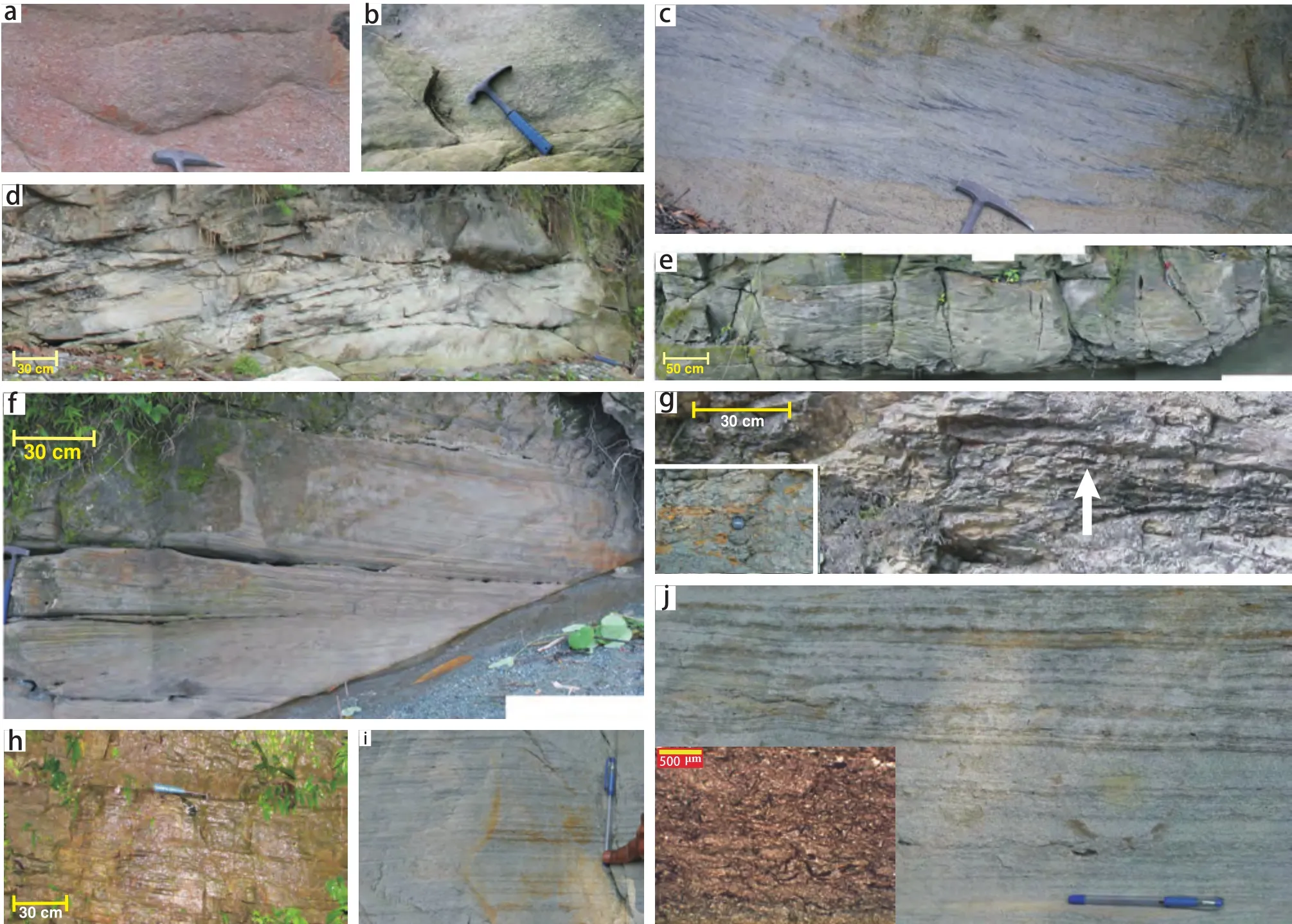
Figure 5 a-Massive pebbly sandstone facies IIA; b-Planar laminated coarse sandstone facies IIB; c-A compound cross-stratified sandstone facies IIC; d-Smaller dunes climbing in direction opposite to the dip direction of larger cross strata bounding them below and above, facies IID; e-Coarse-grained sandstone internally characterized by trough cosets, facies IIE; f-Tabular cross-stratified sandstone, facies IIF; g-Muddy rippled sandstone (iron encrusted burrows within inset), facies IIG; h-Tabular bodies of planar laminated fine-grained sandstone with intermittent inclined mud laminae, facies IIH; i-Pin-striped sandstone facies III, note reverse grading within individual laminae; j-Fine-grained sandstone interlaminated with crinkled carbonaceous laminae (highlighted in photomicrograph within inset), facies IIJ.
Inversely graded planar laminated or pin-striped sandstone facies (III)is only sparingly present in form of small erosional remnants not exceeding 75 cm in thickness and 1.5 m in outcrop width. The most significant aspect of this facies is inverse grading within its individual constituent laminae. Overall the sand is fine-grained and well-sorted (Figure 5i).
Planar and wrinkle laminated muddy sandstone facies(IIJ)is characterized by repeated lateral and vertical alternations between planar laminae and wrinkled laminae. The latter is rich in minute and laterally detached carbonaceous mud laminae (Figure 5j). Thickness of the planar laminae is variable, measuring up to 50 cm. Many of these laminae are discernibly inversely graded. The wrinkled laminae do not exceed 2 cm in thickness. Besides being wrinkled, they bear wart-like structures.
Interpretation
Because of general poor sorting of sediment and lenticular sand body geometry as well as almost ubiquitous presence of trough cross-strata suggests deposition of this association in main channel system of the Siwalik river.Amalgamation of fluvial channel bodies is an imperative.The massive pebbly sandstone facies, the coarsest amongst all the facies, must have been most proximal to the sediment source, deposited, in all probability, close to the fan-fringe. The planar laminated coarse sandstone facies resting on master erosion surfaces likely to have deposited directly on the channel-floor and formed either as linguoid or cross-channel bar (Cant and Walker, 1978; Allen, 1983).In the broad frame of channel deposition the compound cross-stratified sandstone facies appears to represent midchannel longitudinal bar (e.g., Hein and Walker, 1977;Bristow, 1993; Smith and Rogers, 1999; Best et al., 2003;Bose et al., 2008, 2012; Long, 2011). Ripples moved up along the upcurrent side of the bar, crossed across its crest and then moved down its downcurrent side to contribute to accretionary growth of the bar. Upcurrent passage of this facies is the coarse-grained climbing dune facies attributes origin of the latter to upcurrent accretion on the longitudinal bars, presumably in situation of enhanced rate of deposition (e.g., Miall, 1985, 1988; Hadlari et al.,2006; Sambrook Smith et al., 2006; Long, 2011; Bose et al., 2012; Sarkar et al., 2012). The trough cross-stratified sandstone facies is a typical product of channel deposition(Miall, 1976; Long et al., 2011; Bose et al., 2012; Sarkar et al., 2012). Individual trough cosets are attributed to individual channel-fills. Upward decline in cross-set thickness and grain-size evince declining flow velocity along the channels through time. Either progressive decrease in gradient of the depositional surface with channel-filling (Bose et al., 2008) or gradual blocking of the upcurrent channel entry point by shifting bars (Bose et al., 2012). Palaeogeography of the muddy rippled sandstone facies is difficult to ascertain because of characteristics so contrasting from those of the channel facies encasing it below and above in every outcrop. One thing seems certain is its channel-related origin; lenticular body geometry and concave upward base further corroborate this contention. Most probably the contrastingly low energy deposit belongs to oxbow lake (cf., Brooks and Medioli, 2003; Rowland et al., 2005;Pawlyta et al., 2007). Progressive isolation of the lake from the redirected river channel appears to be manifested in upward fining of grain-size, greater frequency in occurrence of mud drapes and reduction in height of the ripples.The rippled sand was delivered possibly during monsoon when some portion of river water spilled over the barrier and flowed along the abandoned channel. Rest of the time in each year the lake stagnated and allowed mud to settle.Through time the spill over reduced. As the lake tended to be filled up and vegetation likely to have grown which led to the preferred concentration of rootlets on top of these facies bodies. The tabular cross-stratified sandstone facies is a likely product of either transverse or bank-attached bar (Todd and Went, 1991; Yu et al., 2002; Mazumder and Sarkar, 2004; Ghosh et al., 2006; Sarkar et al., 2012). Because of its fine grain-size encouraging settling of lightweight twigs, bank-attached bar interpretation is favoured.The planar laminated fine-grained sandstone facies with lateral mud partings is a typical product of levee. The mud partings attest to accretion in successive floods (Milana and Tietze, 2002). The planar laminated fine-grained sandstone facies is typically of aeolian origin. Its inverse grading attests to grain-flow process in deposition; good sorting in sediment grain-size is further corroborative.The planar and wrinkle laminated muddy sandstone facies also resembles levee, possibly a bit further away from river channel with respect to the other aforementioned levee facies, comparatively more favourable for microbial mat growth and preservation. The wrinkled carbonaceous laminae are typical products of microbial mat growth (cf.,Schieber, 1986, 1998, 1999; Sur et al., 2006; Schieber et al., 2007; Noffke, 2010; Samanta et al., 2011; Noffke and Chafetz, 2012). It is relevant to note that the last three facies occur in close association with each other.
3.3 Flood plain association
This association contains substantial proportion of shale and some coal as well. Sandstone is also present, but mostly as isolated bodies. Followings are the facies that constitute this association:
Large-scale cross-stratified sandstone facies (IIIA)is coarse- to medium- grained and internally characterized by cosets of medium-scale (< 55 cm) trough cross-strata.Amalgamation of the same facies is encountered at places. Individual cosets achieve thickness about 1.1 m. They have distinctly lenticular geometry having bases concave upward. Their maximum width of which is estimated to be~4 m. Within the cosets the thickness of constituent sets decreases upward, and the maximum thickness measured~25 cm. The facies is amalgamated at places, the cumulative thickness can measure up to 6.9 m, within which facies thickness decreases upward (Figure 6a).
Small-scale cross-stratified sandstone facies (IIIB)encased on all sides by mud-rich facies, described below, form small channel forms that have distinct concave upward bases (Figure 6b). The cross-strata are troughshaped, but unlike those in the immediately preceding facies, do not exceed 45 cm in thickness. The width of the facies bodies is limited to 4 m. At places these channel sandstone bodies are stacked one above another and consequently contact of this facies, in these cases, with the encasing mud-enriched facies is as steep as 45°. The same contact with isolated channel forms does not, however, exceed 27°. Thickness of the channel-fill sandstones goes up to 45 cm for isolated bodies and 85 cm for amalgamated bodies.
Ripple-laminated sandstone facies (IIIC)is finegrained and often bears coal streaks. Ripples climb and the climbing ripple lamina-sets often amalgamate. Thickness of individual sets measures up to 65 cm, but decreases upward within their stacks. Concomitantly frequency in occurrence of coal streaks increases. Towards the top of the stacks rootlets occur at places (Figure 6c). At top of the stacks the ripple forms are often preserved and have height around 1 cm. The facies units are sheet-like in geometry.
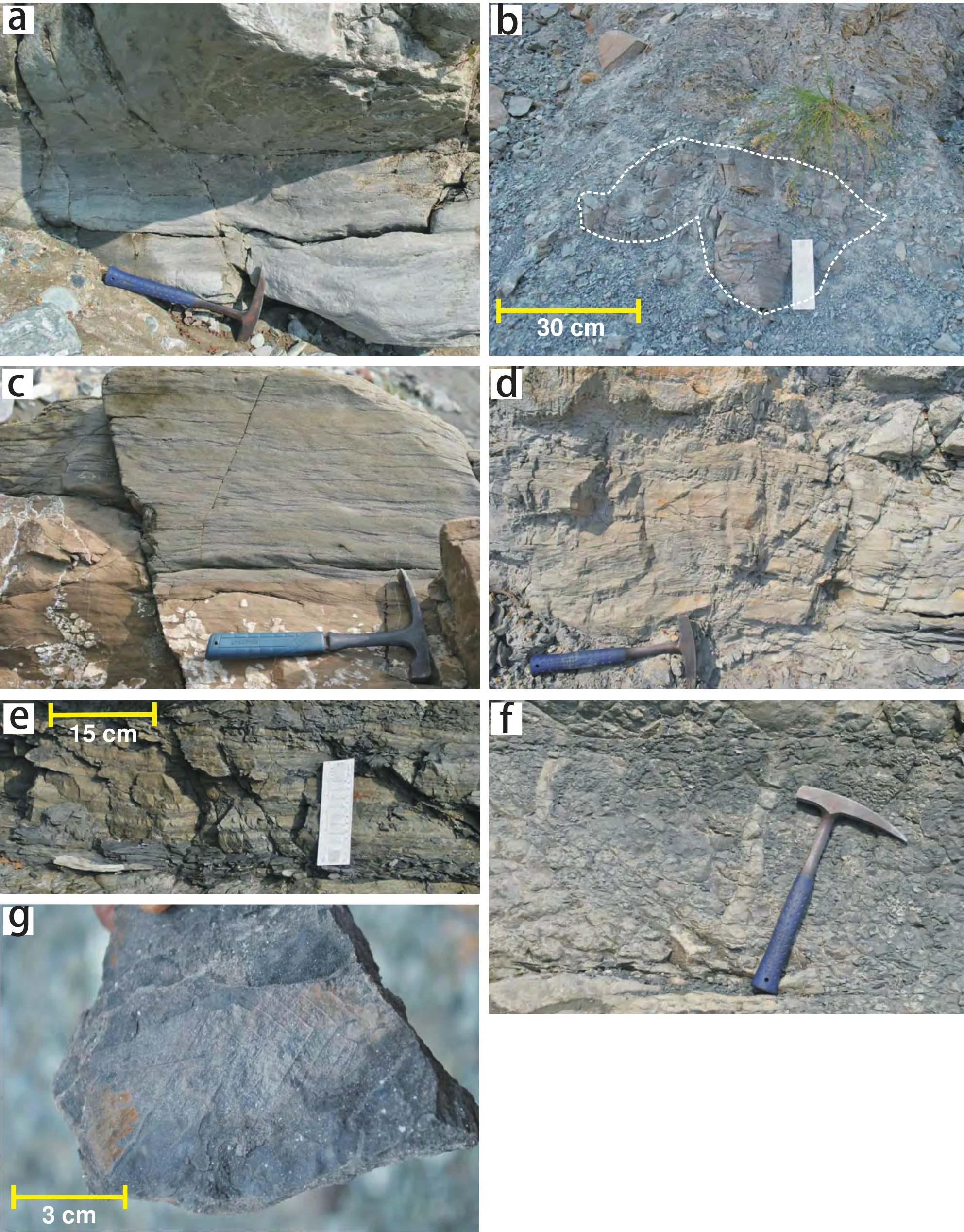
Figure 6 a-Trough cross-stratified sandstone; b-Multiple small channels juxtaposed together and encased by mudstone all around,note its steep contact with mudstone facies IIIF; C-Fine-grained silty sandstone internally characterized by ripple laminae, facies IIIC;d-Fine-grained sandstone-carbonaceous mudstone, with mm-scale alternations depicting sigmoidal cross-stratified facies IIID; e-Frequent alternations between planar siltstone and carbonaceous mudstone, facies IIIE; f-Mudstone with vertical burrows, facies IIIF;g-Impression of Dipterocarpus siwalicus leaf on a bed surface in the facies mentioned last.
Sigmodal cross-stratified very fine-grained sandstone/siltstone facies (IIID)is characterized by thin mmscale dark coloured mud drapes. The cross-strata have low dip, not exceeding 15° in their steepest mid-parts. They as well as the mud drapes dip are in same direction. The cross-strata are normally graded, very fine-grained sandstone giving way upward to siltstone (Figure 6d). The facies units are wedge-shaped, tapering in the direction of dip of the constituent strata. Their dimensions are short,height and outcrop width never exceeds 50 cm and 4 m respectively.
Siltstone-mudstone interbedded facies (IIIE)is characterized by frequent alternations between sheet-like planar-laminated siltstone and massive mudstone (Figure 6e). The mudstone is dark in colour and at places, highly carbonaceous. Wrinkled laminae are common within them.Rootlets are present at places. Thickness of the facies units reaches up to 1.6 m. Overall geometry of the facies is tabular.
In preferred association with the last two facies occurs a mudstone facies (IIIF) that bears thin planar stringers of siltstone. The mudstone is dark in colour and with elimination of siltstone stringers, turns darker, even coaly at places.Rootlet marks and burrows occur frequently (Figure 6f).Leaves also have been documented within this facies (Figure 6g).
Interpretation
This mud-enriched and rootlet-infested association is apparently outside the main channel system and broadly,belongs to the flood plain regime. Lack of bedding plane exposures and brittle nature of the rocks prevent convincing recognition of desiccation cracks. The rootlets, nevertheless, leave little doubt about emergence of some of the constituents of this association. The large-scale crossstratified sandstone facies is apparently channel sandstone,the cardinal difference of which with the trough crossstratified sandstone facies in the preceding association having similar channel origin is that whether, amalgamated or not, it is often encased below and above by the ripplelaminated sandstone facies. Local presence of rootlets in conjunction with organics-rich dark laminae identifies the latter as overbank sediment. Channel-origin is also apparent for the small-scale cross-stratified sandstone facies,but close association with last three mud-rich facies and considerably shorter dimensions suggests that the channels were cut through the flood plain, moving away from the main channel system. Both the ripple-laminated sandstone and the siltstone-mudstone interbedded facies are organics-rich and bear rootlets and inferred to have originated at a distance from the channels, major or minor (Smith, 1983;Smith et al., 1989; Richards et al., 1993). In the sigmodal cross-stratified very fine-grained sandstone/siltstone facies the low angle cross-strata is likely to be accretionary as IHS typical for muddy streams (Marriott and Wright,2004; Ghosh et al., 2006; Lynds and Hajek, 2006). An origin like this in relation to small channels is not unlikely,but the same orientation of the cross-strata and the mud drapes, nonetheless, denies the possibility. The facies may alternatively be related to micro-delta lobe accretion at the terminus of the channels that cut through the flood plain.The mud drapes manifest intermittent accretion. The mudstone facies with planar siltstone stringers and also rich in organic matter is a typical product of distal flood plain (Miall, 1985, 1996; Farrel, 1987, 2001).
3.4 Lacustrine association
This association occurs only as isolated small lenses within the flood plain association. The constituent facies are:
Wedging very fine-grained siltstone facies (IVA)is internally characterized by fine unidirectional cross-strata and carbonaceous mud drapes on them. This facies looks largely similar to sigmodal cross-stratified very finegrained sandstone/siltstone facies in the preceding association, but differs in having its base inclined in the direction of the cross-strata (Figure 7a). The facies units are fining upward and progressively more mud-rich upward.The maximum thickness and outcrop width recorded are 50 cm and 2.6 m respectively.
The wave-rippled siltstone facies (IVB) with streaks of coal is lenticular in geometry having concave upward base and flat top. Many of the ripples are symmetrical in profile. Lamina offshoots and drapes are the dominant internal structures of these silt ripples (Figure 7b). The ripple forms are accentuated in presence of thin drapes of very dark coaly matter on them. The ripples have height around 0.5 cm and spacing ~1 cm. Each facies unit fines upward with increase in the content of coaly matter.
Planar-laminated siltstone-mudstone facies (IVC)is characterized by interlamination of the two lithologies.The shale is very dark in colour, but no rootlet could be recognized as in the siltstone-mudstone interbedded facies of the preceding association. Geometry of the facies is slowly pinching laterally. It is generally found in preferred vertical juxtaposition with the wedging very fine-grained siltstone facies having the transition gradational down-ward and sharp upward (Figure 7c).
Coal facies (IVD)achieves sheet-thickness up to 80 cm. It generally rests gradationally on the immediately preceding facies. The depositional cycles in this association are always fining upward and constituent of this facies occurs on top of them (Figure 7d).
Carbonate facies (IVE), dolomitic in composition, occurs only sparingly as isolated lenses within this muddy facies association. Internally it looks massive, but at many places contain crinkled carbonaceous laminae often bifurcating laterally (Figure 7d).
Interpretation
Pointbar origin of the wedging very fine-grained siltstone can be discarded for the same reason as is done in case of the sigmoidal cross-stratified sandstone facies.Its base distinctly inclined in the same direction with the cross-strata suggests side-filling of a pre-existing depression on the substratum. In the context of the association as a whole this facies is interpreted as a lake-margin deposit.Evidently the lake formed on the flood plain away from the river channel. Siltstone laminae and carbonaceous mud drapes on each of them manifest flood waxing and waning repeated through time and again. The wave-rippled siltstone facies owes its origin possibly to reworking of lakemargin silt deposit by wave created under wind stress on the shallow standing body of lake water. The waves could have reworked the depositional surface only when strong breeze blew; at other times the almost still lake-water allowed mud deposition. Very fine grain-size of sediment indicates a low energy depositional setting for the planarlaminated siltstone-mudstone facies. Nonetheless, the flow shear must have been sufficiently strong to create planar laminae in its silt-grade sediment. Such flows had been intermittent as the mudstone interlaminae manifest.The facies possibly once again records repeated waxing and waning of flood. The coal facies, in the overall depositional context possibly represents peat bogs on the distal end of the lakes having minimal supply of siliciclastics and steady growth of vegetation. The carbonate facies also presumably formed at the distal end of the lakes, but only in those few lakes that had their water alkaline. Microbial mats did grow more favourably during intervals between intermittent deposition.
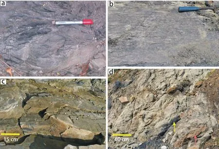
Figure 7 a-Leftward showing wedging body of very fine-grained siltstone, facies IVA, encased by mudstone all around; b-Fine alternations between thin siltstone and mudstone, thoroughly wave-ripple laminated: facies IVB; c-Planar siltstone-mudstone interlaminated body with its right hand part rotated and slightly slumped, facies IVC; d-Lenticular body of coal facies IVD (yellow arrow)and carbonate facies IVE (red arrow) encased by fine-grained siliciclastics.
4 Palaeocurrent
All kinds of available current indicators including imbricated pebbles, taken together, unveil contrast in pattern and direction of palaeocurrent in the four different facies associations, i.e., in the different palaeogeography environments identified. In the alluvial fan association the palaeocurrent had a multimodal data distribution pattern and the mean southwestward (Figure 8). In the main channel the pattern had been close to unimodal, east-southeastward, especially if the data set is weighted for current strength following Miall’s (1976) modus operandi. On the other hand, the current pattern had been multimodal in the flood plain association, even more than that of the fan association. The mean current direction had been southeastward. Current data collection from the lacustrine association was limited for natural reason, for paucity of exposure and current attributes. Nonetheless, current pattern of this association appears consistent with that of the flood plain association. In the following discussion these two associations will be considered together.
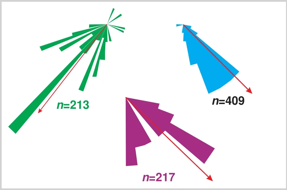
Figure 8 Palaeocurrent roses derived from orientations of cross-strata, ripples and imbricated clasts in all the facies associations but for that with lacustrine origin. Note their unimodal nature and almost orthogonal relationship between those of the alluvial fan association (green) and the main channel association(blue).
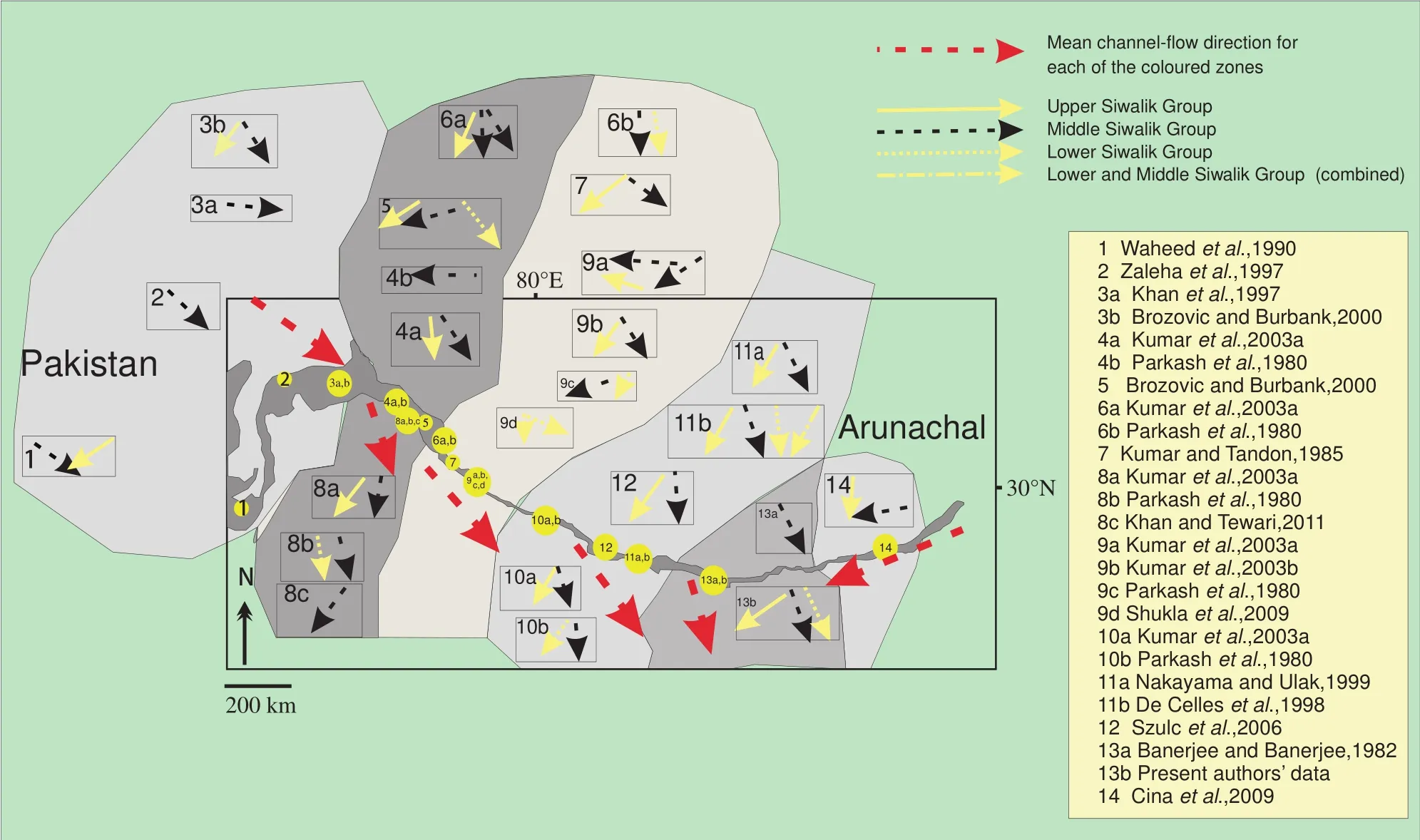
Figure 9 Mean palaeocurrent directions derived from three parts of the Siwaliks viz., namely Lower, Middle and Upper all over the exposure belt along the Himalayan range. Note that the mean zonal directions (red arrow) for the flow along the main channel is over all towards the study area (13) from both west and east. The numbers correspond to the references cited on the right.
Interpretation
The high-angle directional variation in the palaeocurrent between the alluvial fan and the main channel strongly suggests that the latter belonged to an axial river that ran along the mote of the Siwalik foreland. The palaeocurrent direction further swerved southeast rather widely as distributaries encroached upon the flood plain before their eventual termination; there was possibly little flow from peninsular India. The contention for existence of an axial river is corroborated from most of the work sites all along the Siwalik belt, on the basis of similar high-angle palaeocurrent directional variation between the Middle and the Upper Siwalik; a significant exception being DeCelles et al. (1998) at 35° (Figure 9). This author recorded the same southward palaeocurrent in the Middle and Upper Siwaliks. Except this, all other records together indicate flow along the Himalayan foot-hill from both the east and the west converging somewhere near the present study area(Figure 9). Data sets depicting the flow from the east are comparatively fewer; additional affirmation comes from zircon grains found within the Middle Siwalik exposed on the bank of the River Lish that were derived from the gandesic batholith exhumed at immediate north of the eastern extremity of the Siwalik belt in Arunachal (Cina et al.,2009). The combined flow moving from the west and the east must have had a passage somewhere near the study area to move on to the southern plains as do the River Ganges, Tista or Brahmaputra at present. Bouger Anomaly data indicate presence of a north-south elongated basement trough at immediate south of the present study area that at present serves as the outlet of the River Tista and its tributaries like Lish and could have served the River Siwalik as well (Figure 10). If true, the basement trough is pre-Siwalik in origin.
5 Channel pattern
The multidirectional palaeocurrent roses in the fan and flood plain associations are possibly related to expected wide flow dispersal on removal of stringent channel confinement. Pattern of the main channel, nonetheless, had a special role in determining the broad frame of Siwalik deposition. Among the various practices in vogue for determining channel sinuosity from the palaeocurrent data we preferred Miall’s (1976) approach as it is based not only on the degree of dispersion in current data, but also on their values weighted for current strength: P = 1/1-(θ/252)2,where, P = channel sinuosity, and θ is the maximum angular range of the palaeocurrent mean azimuth weighted by cube of corresponding cross-set thickness. The sinuosity value derived from the trough cross-strata of the Middle Siwalik in the study area stands around 1.3.
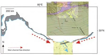
Figure 10 Roughly N-S elongated basement trough based on bouguer anomaly contours (made explicit above) and the suggested route of River Siwalik escaping (blue) onto the plains, emerging from the confluence between the two tributaries from west and east(red arrows). Also note that the main channel flow direction (blue arrow) derived from this study is parallel to the reconstructed course of the River Siwalik emerging from the confluence.
Interpretation
The sinuosity value suggests that the main channel of the Siwalik River had possibly been braided, but with sinuosity not-so-low. May be the River had a hybrid nature.Frequent presence of longitudinal bar favours the braided pattern, but the inferred levee and ox-bow lake deposits favour meandering nature. The typical product of meandering channel, the point bar, did not though come in view during the present study, but the exposure condition had hardly been adequate for recognition of the delicate archetypal interlayer relationship of such mesoforms. Presence of mid-channel bars even within tight loops of meandering channels is not uncommon in modern settings. Tectonic instability of the times of Siwalik deposit, nonetheless, could have caused steepening of the across-channel gradient as much as to exceed the along-channel gradient and thereby encouraged avulsions (Burbank et al., 1996).
Low channel sinuosity values have been derived from five other western worksites, including two at the western extreme, in Pakistan with help of the same formula;fresh recalculation was needed on some instances utilizing the given basic data (Table 1). In the majority of cases braiding was originally suggested. Leaving aside a slight deviation in the trend at Kumaon, a progressive increase in channel sinuosity value towards the present worksite becomes apparent.
6 Palaeohydraulic parameters
Channel dimensions are potent guides for river hydraulics, but measurable only rarely in rock records and that too generally for smaller ones. Palaeohydraulic estimations are, therefore, generally indirect. Palaeochannel depth, the most useful parameter, can be estimated from decompacted thickness of cross-sets provided they indicate a broad uniformity in geometry of the parent bedforms through time and space (Leclair et al., 1997; Bridge and Tye, 2000). Different empirical relationships relating medium-scale cross-set thickness and channel depth and other hydraulic parameters have been proposed and are widely in vogue (Leopold et al., 1964; Yalin, 1964; Allen,1968, 1970; Schumm, 1968a, 1968b, 1969, 1972; Leeder, 1973, 1978; Ethridge and Schumm, 1978; Osterkamp and Hedman, 1982; Williams, 1984; Bridge and Mackey,1993a, 1993b; Bridge and Tye, 2000; Leclair and Bridge,2001; Ito et al., 2006). Although different formulae yield results slightly different, each of them is robust enough to support comparative studies (Eriksson et al., 2008; Bose et al., 2012). In the present analysis we adopt only those empirical formulae that are not dependent on any statistically assumed constant so that greater respectability could be injected into the estimates. The formulae used are:

where, h is cross-set thickness and
dm= mean palaeochannel depth in metres (Allen, 1968).

where, wm= mean channel width in metres (Bridge and Mackey, 1993a, 1993b; Ito et al., 2006).

where, Qm= mean annual discharge in m3/s (Williams,1984).

where, wb= bankfull channel width in metres (Osterkamp and Hedman, 1982).
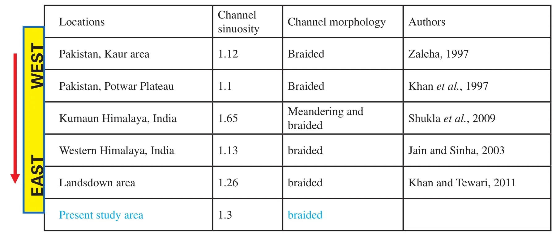
Table 1 Channel sinuosity (main channel association) over the entire Siwalik belt

where, db= bankfull channel depth in metres (Leeder,1978).

where, S = palaeoslope in m/m, and F = channel width/depth ratio (Schumm, 1972).

where, Qb= bankfull channel discharge in m3/s, and Abis the bankfull cross-sectional area represented by (wb× db)(Williams, 1978).

where, Ad= drainage area in km2(Leopold et al., 1964).

where, L = Principal Stream Length in km (Leopold et al., 1964).

where, cbw = mean channel belt width in metres (Bridge and Tye, 2000).
The cross-set thicknesses were measured from the trough cross-stratified sandstone facies within the main channel facies association in the present study area and averages of various palaeohydraulic parameters were estimated with help of the aforementioned formulae (Table 2a; Figure 11). The Table 2b also collates the averages of published values of the same parameters estimated at other worksites along the Siwalik belt both on the west and the east of the study area.
Interpretation
Apparently the Siwalik River turned out to be a very large river in the study area, because of confluence of two major tributaries. Its estimated channel-belt width had been larger than the maximum for the Brahmaputra River(14.03 km; Lahiri and Sinha, 2012) and the Mississippi River (10.04 km; Williams, 1986). Its mean annual discharge had been somewhat lesser, but fairly comparable with that of the Brahmaputra River (21,200 m3/s) and the Mississippi River (17,000 m3/s). The Table 3 shows almost a steady increase of discharge from the western extremity of the Siwalik exposure belt towards the present study area; only the data from Kumaon deviates. Almost three-fold increase supports, though not unequivocally, continuity of a single river from the western end to the present study area onthe Siwalik belt. Positioning of the southward passage of the Siwalik River somewhere close to the present study area seems highly plausible once more.

Table 2a Palaeohydraulic parameters in the study area
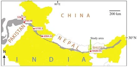
Figure 11 Calculated discharge (in m3/s) of the River Siwalik at different stations shows progressive increase from west towards the study area in the east of the Himalayan belt.
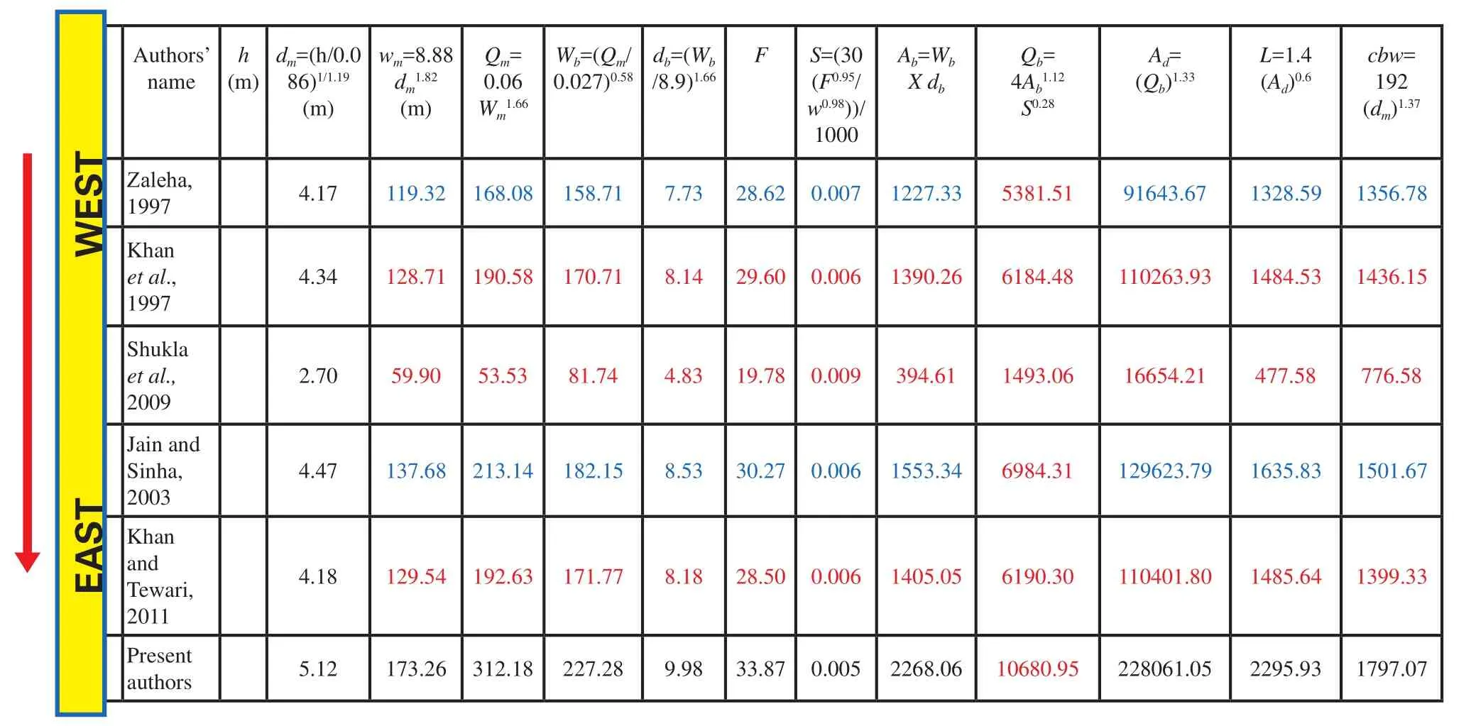
Table 2b Palaeohydraulic parameters over the entire Himalayan belt
7 Palaeoclimate
7.1 Oxide and elementary chemistry
All Siwalik sandstones are of salt and pepper colour and petrographically belong to the litharenite-sublitharenite family, as expected in the foreland system of their deposition. A wide spectrum of sedimentary rock fragment constituents point to a recycled origin of the Siwaliks as a whole. Evidently the erosion rate exceeded the rate of weathering. For an independent assessment of weathering at sediment source and the depositional site major oxide and trace element geochemistry was taken recourse to, especially for mudstones of the flood plain association and also for a few sandstones of the flood plain and the main channel associations.
The Siwalik rock samples, pulverized and screened through a 200 mesh sieve, were studied with help of XRF on a Philips MAGIX PRO Model 2440 instrument through the Pressed Pellet method (Govil, 1985). For trace element study Perkin Elmer SCIEX, model ELAN®DRC II ICPMS(inductively coupled plasma spectrometry) and open acid digestion sample preparation procedures (Roy et al., 2007)were adopted. The work was done in National Geophysical Reseach Institute, India and internationally acknowledged standard GSR-4 was run simultaneously for reference.Replicate analyses of samples indicate that error is better than 1% for major elements and ±2% for trace elements like Rb and Sr.
Assuming that weathering likely to have increased Al2O3content at the cost of K2O, Na2O and CaO the nondimensional CIA values (Chemical Index of Alteration;Nesbitt and Young, 1982) were calculated and the nondimensional value varies from 82-75 for the flood plain mudstones and 59-77 for the sandstones of the same association and 56-72 in the Main Channel sandstones.
However, since SiO2and K2O contents maintain negative relationship, the possibility of addition of K2O during diagenesis cannot be ruled out. Hence CIW (Chemical Index of Weathering; Harnois, 1988) values ignoring the K2O content, were also calculated for the same sediments.The latter averages ~95.19 in the mudstones, 93.15 in the flood plain sandstones and 85.46 in the main channel sandstones. On the other hand, PIA (Plagioclase Index Alteration; Fedo et al., 1995) value that recommends subtraction of K2O content averages 89.8, 62.8 and 58.78 for the aforementioned group of rocks in given order.
The ICV (Index of Compositional Variability; Cox et al., 1995) value that takes into consideration an enlarged list of major oxides for purported enhancement in credibility of weathering proxy, averages 1.9, 2.1 and 2.4 in the same group of rocks arranged in the same order.
Sr having smaller ionic radius with respect to Rb, suffers comparatively more rapid leaching and thus the Rb/Sr ratio is conceived as a good proxy for the degree of weathering achieved (McLennan et al., 1993). Within the Siwaliks, the mudstone of the lacustrine association yields the highest, being around 2.56 whereas mudstones of the flood plain (outside the lakes/ponds) origin possess an average 1.88. In the sandstones of flood plain and main channel associations the averages are 1.05 and 1.7 respectively.
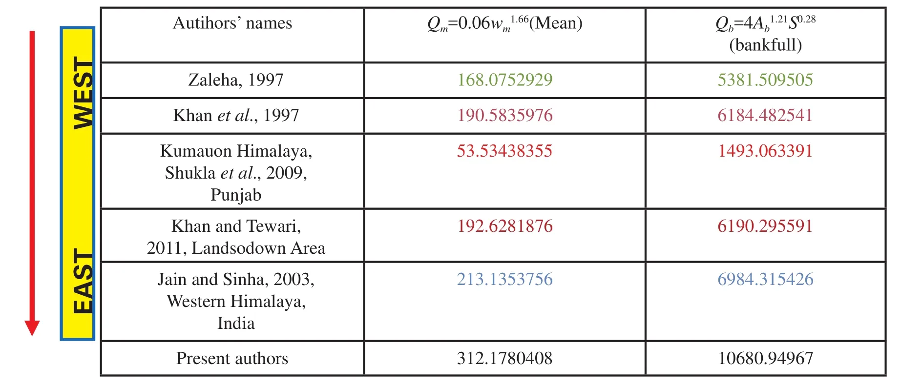
Table 3 Discharge variation in Siwalik main channel from east to west
Interpretation
The CIA value being 70-75 for “Average Shale” (Visser and Young, 1990), its distinctly higher range in the Siwalik flood plain mudstones suggests intense weathering at source, even though the sandstones yield lower values.The general high weathering rate gains support also in the corresponding CIW values. The ICV values are, nonetheless, well above those of clay minerals and in the range of feldspars and suggest not-so-high weathering rate at source. Since the negative correlation between SiO2and K2O suggests presence of K2O in the clay fraction, the CIW is presumably a more sensitive proxy for the weathering than the other two parameters. It is more sensitive than PIA as well because preservation of plagioclase at source is of little relevance in case of recycled sediments like the Siwaliks. Rb/Sr ratios in shales are, in general, 0.80-0.88 (cf.,Turekian and Wedepohl, 1961; Gromet et al., 1984; Taylor and McLennan 1985) and in that comparison also the weathering rate at source of the Siwaliks had been high; the ratio is highest in the lakes as is expected (Chaudhuri and Brookings, 1979). The ratio is somewhat lower in the Siwalik sandstones, but it might have been significantly influenced by detrital mineralogy (Graham Shield, pers. com.).
The same parameters from other worksites over the entire Himalayan belt are collated or calculated freshly from the given compositional datasets for comparison with those derived from the present study area (Table 4a-4d).Plotting their regional averages from the western to the eastern end all the weathering indices, irrespective of their relative merit, reveals a weak trend of weathering intensification (Figure 12). Significantly the same eastward weathering intensification is noted also at present as well along the Himalayan foothills, perhaps a bit more accentuated.Therefore, the palaeoclimate had been overall humid in the study area, in the eastern Himalayas as it is now. The imperative is that the Himalayan mountain belt had already acquired its present configuration, more or less, and its role as a watershed by the time Siwalik deposition began does not cause any surprise; the Siwaliks are post-orogenic (Mitra et al., 2010; and references therein).
7.2 Isotope geochemistry
To estimate the rate of rainfall and temperature recourse was taken to determination of δ18O for direct correlation and of δ13C for indirect correlation from the carbonate contents of eight samples, four of them are limestones from the lacustrine association, two are shales and two are sandstones from the flood plain association. Powdered rocks were made to react with ~98% phosphoric acid at 72°C in sealed reaction vessels flushed with helium gas. Headspace sampling of evolved carbon dioxide was performed with a Finnigan Gas-Bench and isotopic ratios measured.Since gas bench introduces slight fractionation in δ18O over a range of sample weight, it is necessary to carry out the linearity correction for the samples. This was done by analyzing large number of standard NBS-19 carbonate with size varying between 10 and 400 μg. BDH (Univ.Coll. London) and Z-Carrara (PRL/Cambridge Univ.) δ13C(2.1‰), δ18O (-2.1 ‰) relative to VPDB standards have been utilized. The evolved CO2was purified cryogenically before measuring δ18O with a GEO 20-20 stable isotope ratio mass spectrometer (CFIRMS) at the National Stable Isotope Facility of IIT, Kharagpur. Typical experimental precision of ±0.1 ‰ was maintained. In the lacustrine carbonates the values obtained range from -11.7‰ to-12.6‰, in the shales they are -13.2‰ and -14.2‰ and in the sandstones -16.7‰ and -18.2‰.

Table 4a Weathering indices in the study area (CIA, CIW, CIA/CIW, ICV and PIA)

Table 4b Rb/Sr ratio in the study area
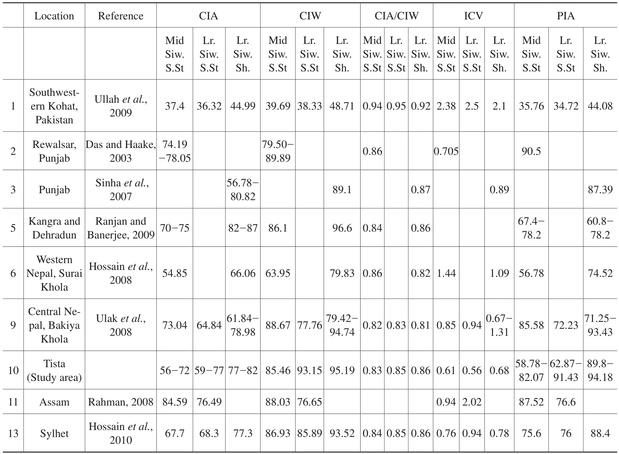
Table 4c Weathering indices variation over the entire Siwalik belt
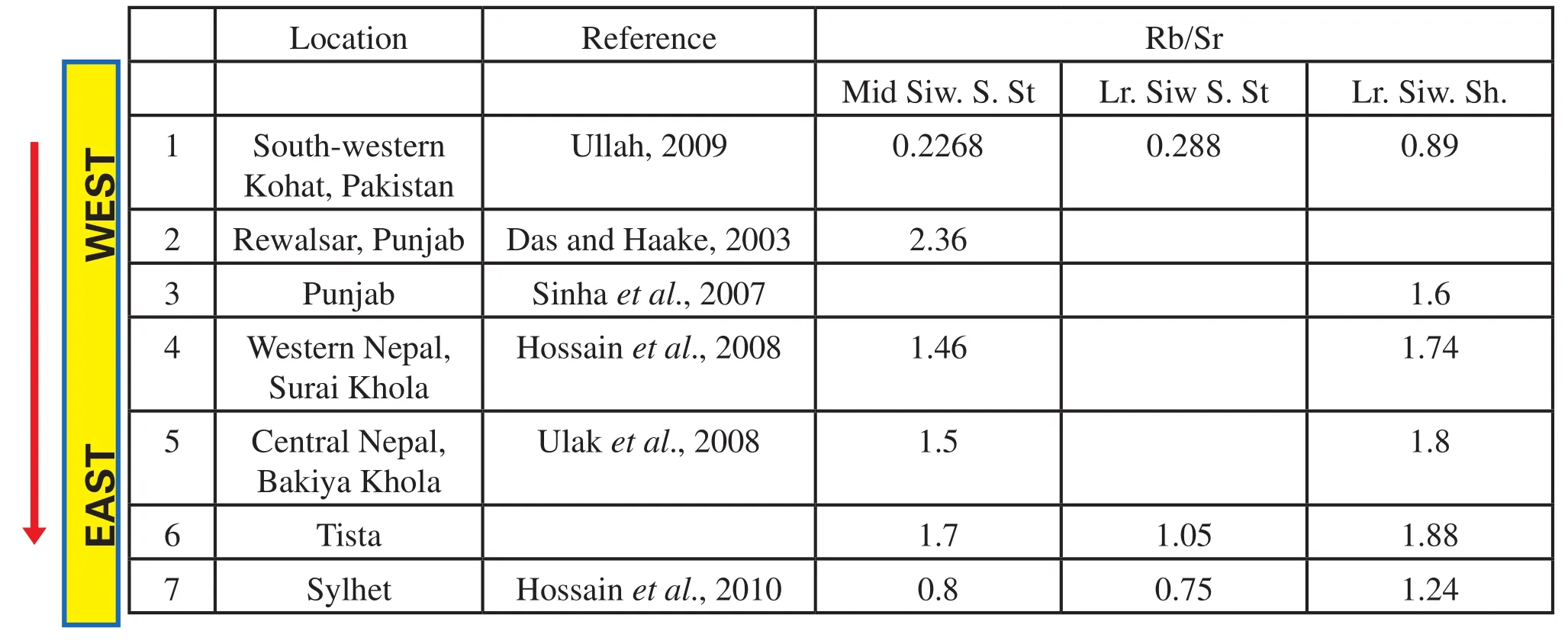
Table 4d Variation in Rb/Sr ratio over the entire Siwalik belt

Figure 12 Progressive increase in Al2O3 content of the Lower Siwalik shale from west to the present study area.
Preliminary though the investigation is, the few δ18O data obtained point unequivocally to considerable18O depletion which is well consistent with precipitation far inland, in extra peninsular India, guarded from high latitude air by the Himalayas (Krishnamurthy and Bhattacharya, 1991). On the other hand, primary enrichment in13C is explicit despite the fact that burial cements in sandstones were somewhat depleted, the δ13C assumed negative values.
Interpretation
General enrichment of samples, especially the carbonate ones, in13C is in consonance with the existing consensus that the transition from C3to C4vegetation had already set in (Ehleringer et al., 1991; Quade et al., 1989, 1995).Taking into account published data from other Lower Siwalik exposures too, all on the west of the study area, the fact appears valid for the Siwalik belt in general; however,a clear tendency for13C enrichment eastward becomes apparent (Table 5). Considering the average δ18O in lacustrine carbonate deposits the palaeotemperature in the study area is calculated to be ~26.5°C (Friedman and O’Neil,1977). Assuming that soil water had been in equilibrium with rainwater in terms of δ18O, the annual average of the rainfall had been around 1604 mm/year in the present study area (following Dansgaard, 1964; Yurtsever and Gat,1981; Yapp, 1982). It is interesting that Krynine’s (1937)estimation of mean annual temperature 70°F-80°F (21o-26oC) and annual rainfall > 50 inches (1270 mm) from Pakistan Siwaliks taking into account both pre- and postdepositional decay and the abundance of hematitic concretions had been a close call. The given or freshly calculated rainfall data for other worksites, as presented in Figure 13,manifest an overall tendency for increase in rainfall rate also eastward. It is further interesting that the same tendency, increasing, eastward prevails at present too, though the rate has considerably decreased (Table 5; Quade and Cerling, 1995). The imperative probably is that the Himalayan range had acquired its present configuration back in 8.5 my when the Lower Siwalik was deposited (Najman et al., 2001) is further corroborated.
8 Conclusions
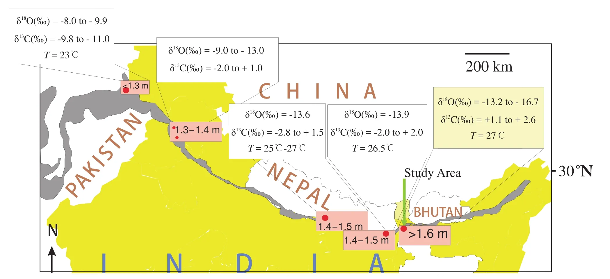
Figure 13 Spatial variation in δ13C and δ18O and palaeo-temperature as well as palaeo-rainfall (pink boxes, in unit m/yr) derived from δ18O along the Siwalik exposure belt. Note progressive enrichment in δ13C and depletion in δ18O, increase in palaeo-temperature and increase in palaeo-rainfall towards the study area from west.
Four facies associations, viz., alluvial fan, main channel, flood plain and lacustrine comprise the Mio-Pliocene Siwalik Group exposed in Darjeeling-Jalpaiguri Districts,eastern India. Constituent facies localized preferably above and below the level of intersection between the ground water table and the fan surface, between in-channel and channel-margin, between flood plain distributaries and interdistributaries, and between lake-margin and lake-interior improve palaeogeographic visualization appreciably.Multimodality on the fan and the flood plain in palaeoflow vector contrasts with virtual unimodality in the main channel. The latter was the axial river in the Himalayan Foreland system that bore a hybrid pattern, avulsions being encouraged spatially and/or temporally by tectonism.The observation is generally the same all over the 2000 km-long Siwalik belt, but the channel-sinuosity value,generally increased from the western extremity eastward.Similar increasing trend is noted also in case of depth,width, discharge and channel-belt width. All available palaeocurrent vector data along the Siwalik belt strongly suggest confluence of two tributaries, one from the west and the other from the east, very close to the present study area from where the Siwalik River must have escaped onto the Indian plains. The north-south elongated basement trough that the River Tista and neighbouring streams presently follow could have provided the escape route for the Siwalik River too. Moderate to high weathering indices elicit wet palaeoclimate. Different weathering indices, some ambiguity notwithstanding, indicate general increase in humidity eastward. Spatial variation in precipitation and temperature had been, more or less, consistent increasing from west to the present study area that recorded ~27oC.The modern trend is the same increasing eastward across the study area and indicates that the Himalayan Mountain belt had already acquired its present configuration and role as a water shade during the Siwalik time. Transition from C3to C4vegetation had already set in.
Acknowledgements
The authors are greatly indebted to Profs. Graham Shields-Zhou and Tadeusz Peryt for reviewing the manuscript and improving its quality. Sunipa Mandal acknowledges to UGC, Minor Research Project, Government of India (F.PSW-032/08-09_ERO) for financial support.Pradip K. Bose and Subir Sarkar gratefully acknowledge financial help from DST (ESS/16/243/2006-EMR--II). Subir Sarkar also acknowledges financial help from UPE-II programme of Jadavpur University. All the authors express gratitude to their respective institutions for infrastructural facilities and research support.
杂志排行
Journal of Palaeogeography的其它文章
- Late Miocene wood flora associated with the Yuanmou hominoid fauna from Yunnan, southwestern China and its palaeoenvironmental implication
- Coevality of the sea-level fall and main mass extinction in the Permian-Triassic transition in Xiushui, Jiangxi Province, southern China
- Clay minerals in the Pliocene-Quaternary sediments of the southern Yangtze coast, China: Sediment sources and palaeoclimate implications
- Evolution regularity of the Neogene shallow water delta in the Laibei area, Bohai Bay Basin, northern China
- Siliciclastic-carbonate mixing modes in the river-mouth bar palaeogeography of the Upper Cretaceous Garudamangalam Sandstone (Ariyalur, India)
