论电动汽车的发展趋势
2014-07-24徐国卿徐坤张琦郑春花梁嘉宁周翊民香港中文大学机械与自动化工程系香港999077
徐国卿徐 坤张 琦郑春花梁嘉宁周翊民(香港中文大学机械与自动化工程系 香港 999077)
2(中国科学院深圳先进技术研究院深圳518000)
论电动汽车的发展趋势
徐国卿1,2徐 坤2张 琦2郑春花2梁嘉宁2周翊民2
1(香港中文大学机械与自动化工程系 香港 999077)
2(中国科学院深圳先进技术研究院深圳518000)
文章基于使用电机与主动安全控制实现全制动能量回收以提高能效的原理,提出了纯电气化车辆(Pure Electri fi ed Vehicle, PVE)的概念。阐述了该类车辆具有通过电机可感知车辆运动状态的特点并介绍了相关智能检测方法以及车辆机电解耦的动力学控制结构。讨论了该类车辆的动力学控制方法及驾驶节能策略。最后,从智能化电动车的层面,讨论了驾驶辅助安全技术和人文关怀技术。
全电气化;牵引控制;再生制动;能源控制;人性化
1 Introduction
The development of the electric vehicle (EV) has attracted much attention due to the current environmental pollution issues and energy crisis worldwide. During the performance improvement and industrialization procedure, how to increase the energy storage and usage efficiency are two urgent problems to be solved[1,2].
With the development of electric vehicles, the pure electric vehicles (PEV) have been attracting attentions of consumers and vehicle companies because of its simple power system architecture, energy coming from grid directly, and convenient vehicle arrangement. At the same time, four wheel independent drive vehicles, especially four wheel independent steering vehicles, with short drive chain and good mobility, have advantages in parking, small radius steering and pivot steering. As a result, PEVs have a good potential market in the world. The small low-speed PEVs can be seen everywhere in Shandong province, China. Although they are not technically advanced, they are easy to use.
However, the battery energy density of PEVs cannot be compared with fuel nowadays. The PEVs also have disadvantages in battery weight, safety performance and battery cost. The market performance of PEVs with advanced technology doesn’t meet the expectations of people.
From the aspect of energy eff i ciency in vehicles, the total energy efficiency is low for all vehicles. When running in braking, fuel vehicles consume the kinetic energy in the way of mechanical friction. The braking energy (during stopping and speed reduction) will sometimes account for about 50% on average of all the effective traction energy, which can be seen in table 1. In China, according to the GB/T 18488.1-2006, the stop and speed reduction during basic city cycles occupy 30.77% and 17.44% respectively. If the energy used for stopping and speed reduction can be recollected and stored, the collected energy can be released for reuse. It can greatly improve the energy eff i ciency of the vehicles, and increase the driving mileage.
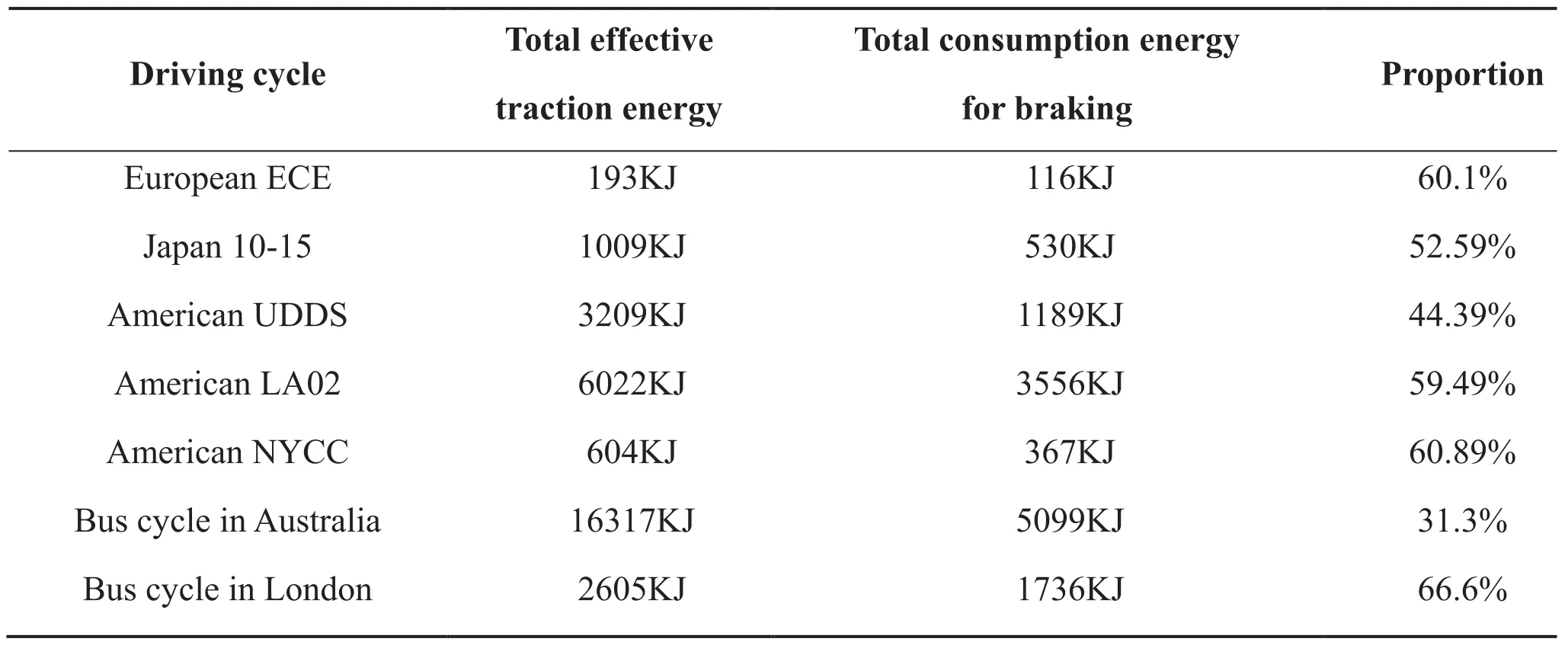
Table1. The averaged traction energy in different types of vehicles
As a result, braking energy recovery is of great significance to improve the energy utilization eff i ciency of EVs. Currently, for the consideration of safety, whether HEV or PEV adopts the method with the combination of mechanical braking used in the fuel vehicles and regenerative braking by electrical motor. The braking safety is guaranteed by the ABS in this method. When electric braking is used in EVs, the driving motor is in the power generation state, which can send part of the power energy back to the battery for charging. It can improve the energy efficiency of the vehicles, increase the driving milage, reduce the mechanical friction of the braking system and extend the length of the mechanical braking system. It has been pointed out that the regenerative braking can increase 8-25% of the driving distance of the EVs[3].
It will be a big challenge to send all of the energy back to the storage system during vehicle stopping and speed reduction for charging and braking safety.
In light of that pure electrical motor driving and pure electrical motor braking are used to realize all power energy recovery in vehicles, we call this type of EVs as novel pure electrif i ed vehicles (NPEV). It is obvious that the energy eff i ciency in NPEV can be greatly improved and much higher than that in HEV/ EV with part of mechanical braking. The mileage in NPEV can be expected to 75% increase, which is calculated in the condition of braking energy accounting for 50% of driving energy. It is much longer than the present 8-25% of mileage increase in HEV/EV currently.
There are two challenges needed to be solved. The first is the feasibility of recovering all braking energy, which needs to deal with two problems:
(1) how to guarantee suff i cient force in low speed or stationary state by motor control;
(2) how to make the braking energy to change the storage systemm fast. The second one is how to realize dynamics control to enhance the safety during regenerative braking.
Another problem addressed in this paper is runsaving control for pure electrified vehicles. It will be focused on how to optimize running conditions in real traffic environment for the issue for vehicle components to improve eff i ciency, which will not be addressed in this paper.
Whether to be accepted by people, except for high energy eff i ciency and high safety, is also very important from the point of view of development of vehicles. The information and intelligent technologies are required to improve the pleasure of driving and human comfort. The safety assistant driving technologies are addressed from the aspect of drivers’ personal behavior. It has been pointed out that human care will become the development direction of vehicles in the future. The relevant research results will also be presented in the paper.
The remainder of the paper is organized as follows. Section 2 analyzes the motion control and regenerative energy in EV. Energy management and predictive control are explored in Section 3. Intelligent driving technologies including lane detection and autopilot driving are studied in Section 4. Human-machine interaction is analyzed in Section 5. Conclusions and discussions are given in Section 6.
2 Explorations of Novel Methodology for EV Dynamic Control
Serving as the actuator for vehicle dynamiccontrol, electric motor has much better performance as compared with conventional internal combustion engines. The electric driving system has distinct advantages, such as quick response, easy measurement, and precise control of motor torque[4], available flexible driving architecture[5,6], and regenerative braking[7], etc. Such advantages can be used to improve the performance of vehicle dynamic control. This section introduces two novel technologies to advance the electric vehicle dynamic control in terms of parameters estimation and electromechanical decoupling structure.
2.1 Estimation of Tire-Road Contact Using Internal Electrical Signals
Most of the researches on the tire-road estimation in the literature are based on the traditional internal combustion engine (ICE) vehicles. For electric vehicles, the electric parameters of the motor, such as the armature current and voltage are more convenient to obtain, which is a signif i cant advantage for estimation. A new concept is to explore the novel estimation methods using the internal electric parameters of the electric motor instead of the outer speed sensors. The following two issues should be studied:
(1) How does the road condition influence the electrical parameters, such as when the road surface changes?
(2) How to estimate the road conditions using the electrical parameters.
With the voltage controlled DC motor, the given voltage is calculated from the torque or current command using the equivalent inverse system based on the linear approximated model of the vehicle. It is a feed-forward open-loop control essentially. The controlled current is more vulnerable to the load change, as compared with the current feedback control. However, from the viewpoint of inhibiting slip, it can eliminate the slippage naturally. The increased wheel rotation can make the back-EMF increase, eventually inducing a quick drop of the armature current. As a result, the motor drive torque will be naturally reduced, and further increase in the slip can be inhibited accordingly. Another motor control mode of the closed-loop current control is widely used in general motor driving applications. From the perspective of the slip ratio control, the current control is not sensitive to the disturbance or the change of the tire-road contact, therefore the current control is not conducive to eliminate the slippage unless the given current is reduced adaptively to the current in tire-road contact. As the disturbance from the tire-road contact is included in the closed-loop of the current control, the armature current becomes unsensible. However, the given armature voltage, produced by the controller, will change obviously, reflecting the variation information of the tire-road contact.
As the electrical signals of motor vary with the load current caused by the tire-road change, they can be used to estimate the current tire-road friction coeff i cient.
Friction coeff i cient estimation: assuming that the DC motor works in a closed-loop current control mode, both the first-order and the second order derivative of the armature current are considered as zero. Then the novel estimation equation of friction coefficient is obtained as Eq. (1), where only the armature voltage and the armature current measurements are needed, which can be obtained through the hall voltage sensor and the current sensor respectively. In the current control mode, the givenaverage armature voltage comes from the current controller (e.g. the PI controller), and then the voltage is then applied to the motor armature through the PWM power driver. As in practical application, the voltage output produced by the current controller is generally discrete; the signal fi ltering of voltage is needed to calculate the differential operation.

Slip ratio estimation: the estimation of the slip ratio can be derived by Eq. (2) from the def i nition of slip ratio, the vehicle longitudinal dynamics model, in which the complex and inaccurate measurement of vehicle speed is not needed, as well as the wheel speed measurement[8]. The signal filtering of the armature voltage is introduced due to the differential operation.
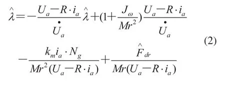
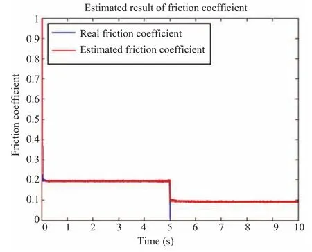
Fig.1. Friction coeff i cient estimation using motor current and voltage
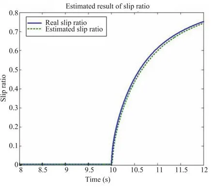
Fig.2. Slip estimation using motor current and voltage
A simulation with a sudden alteration of road surface changing from the dry asphalt to the icy road is introduced. Fig. 1 shows the accurate estimated friction coeff i cient using only the motor current and voltage. Fig. 2 shows the accurate estimated slip ratio using only the motor current and voltage. Due to the signal fi ltering of the voltage and the current, and the integration operation, there is only a little delay compared to the real slip ratio.
As there is no need of additional sensors, the reliability of vehicle control is improved, and the cost is reduced which can help implement the advanced TCS/ABS for electric vehicles. In addition, the novel estimations of tire-road friction coefficient and slip ratio, which can be achieved quickly just within the scope of the electrical time constant domain. The active safety based on the vehicle dynamics control, e.g., TCS/ABS, can be implemented within the motor controller. Therefore the active safety can be improved more quickly and more precisely, as compared with the existing methods.
2.2 Electromechanical Decoupling Structure for Pure Electrif i ed Braking Control
The traditional four-wheel driving car requires a complex mechanical system, and can not be controlled individually for each wheel torque. Electric vehicle using in-wheel motor can be achieved for each wheel independently driven, and thus can precisely control each wheel torque, making the car control performance greatly improved. It is very fast using electrical parameters to control electric vehicle, since it has no mechanical delay in control.
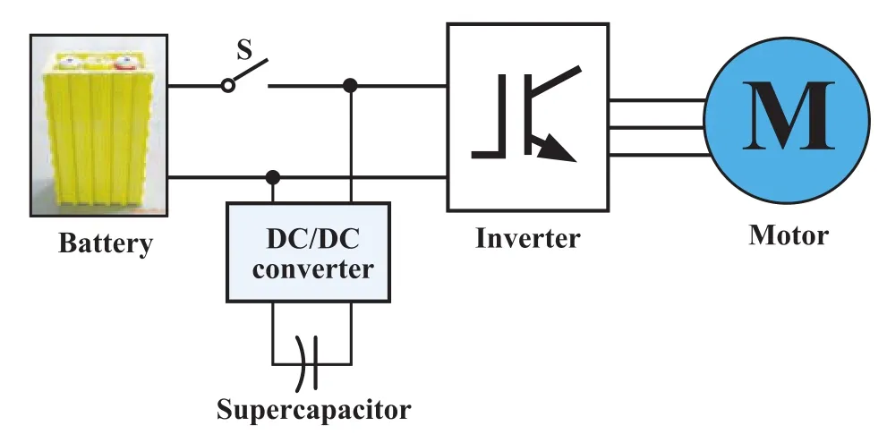
Fig.3. The full energy feedback motor drive system
A novel pure-electrified-regenerative-braking system structure is proposed with the concept of electromechanical decoupling, including power battery module, DC/DC converter module, super capacitor module, inverter and driving motor. The super capacitor is connected to the dc-link through the DC/DC converter. When the drive system operates in the driving mode, the power switch is turned off. The battery and super capacitor supply energy to inverter together. So the high peak power can be provided from the hybrid energy source to improve the dynamic performance. In the regenerated mode, when the feedback energy will charge the battery and super capacitor simultaneously at the beginning. With the speed reduction, the power switch is opened at the half of rated speed. At this time, the voltage of dc-link is dependent on DC/DC converter. So the dc-link voltage can be controlled to fit the back EMF and obtain big enough negative torque. The regenerative energy retrieved from the motor can be fed directly to the battery for charging or supercapacitor. The battery can be charged via DC/ DC when SoC is low. With the aid of this structure (shown in Fig. 3), the energy can be fully recovered without the SoC constraint. For the EV application, the low speed braking is very important. The current ripple of conventional motor is high at the low speed braking due to high voltage of dc-link. The proposed motor drive system can reduce the current ripple to make braking smoothly. When the vehicle is stopped, the motor control is changed from current control to position control. The position control of proposed drive system is similar to servo motor control.
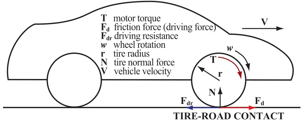
Fig.4. Vehicle longitudinal dynamics
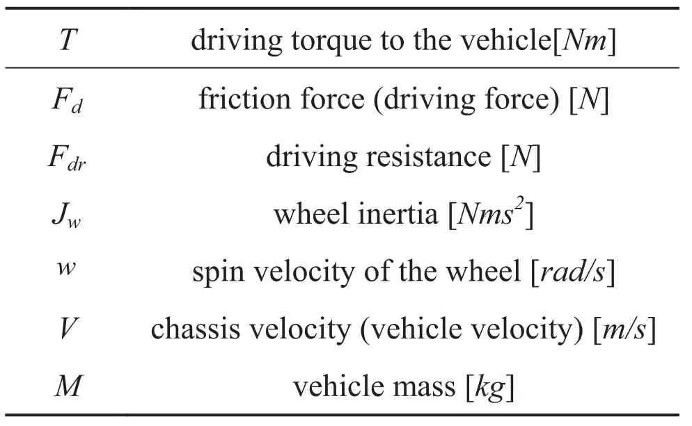
Table2. The meaning of the signals
3 Novel Traction Control and Regenerative Braking Control
3.1 Vehicle Dynamics Model
The multi-power systems make EV a complex mechatronic system. The drive torque produced by the electric motor is transmitted through the transmission, clutch and differential gear to drive the wheels. The wheel rotates under the action of the drive and the friction forces. The main resistance is produced by the contact of the road and the tyre, which contains strong nonlinearity and uncertainties. As only longitudinal case is discussed in the TCS/ ABS system, the dynamic longitudinal model of the vehicle is described in Fig. 4. We assume that drive forces and friction forces on the left and the right tires are the same, the dynamic equations of the wheel and the vehicle take the forms as:
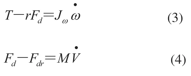
The tire-road contact provides two horizontal forces onto the vehicle: the side force (or the lateral force) and the driving force (or the longitudinal force). These two forces strongly depend on the slip ratio defined by Eq. (5), where e is a small constant to avoid the zero denominator. The friction coefficient is an empirical function of slip, known as the mu-slip curve. The most well-known model for this relationship is the so-called ’Magic Formula’which we plot in Fig. 5 for traction case on a variety of road surfaces.

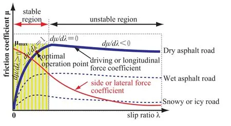
Fig.5. Friction coeff i cient and slip ratio
Fig.5 shows that μ is an increasing function of λ until a critical slip value where μ reaches μmasthen decreases. The driving force of the vehicle or longitudinal force can be described in Eq.6. The increase of slip ratio can increase the driving force between the road and the tire due to an increase of μ It reaches the maximum at the operation point of dμ/d=0, but further increase of the slip ratio will reduce the driving force and induce an unstable acceleration of the wheel, until the driving torque is reduced. Therefore, if the slip ratio is bigger than the optimal slip ratio λopt, both the driving force and the side force will be diminished drastically, and such a loss of the two forces is extremely dangerous. Hence, the region in Fig. 5 where the slip is less than the optimal slip is described as the stable region in this paper, and the unstable region is the contrary. In some literature the optimal slip ratio can also be considered as the operation point with dμ/dλ=1 where the friction coeff i cients of the side force and the driving force are both high[9].
3.2 Novel Traction Control System
Researches on the novel TCS for EV taking full advantages of electric motors have been explored during the past decade. Hori et al. proposed the model following control (MFC) and the optimal slip ratio control using the quick and precisetorque generation of DC motor, and the improved TCS performance were demonstrated using a test vehicle[4,10]. Colli et al. proposed two adherence gradient controllers based on a fuzzy logic and a sliding mode method respectively, tracking the adherence derivative in a wide operating range without any knowledge of the road conditions[9,11]. Yin et al. proposed a novel traction control based on the maximum transmissible torque estimation which is estimated in real time using the driving motor, to follow the estimated value directly and constrain the torque reference for slip prevention[12,13].
The control scheme for vehicle traction should deal with the driver’s handling and the anti-slip control together while satisfying the dynamic and steady stability and ride comfort. Fig. 6 shows the novel traction control scheme to combine the optimal slip ratio control and the driver’s handling during acceleration, where a slip ratio error judgment unit is designed and placed in front of the slip ratio controller. In order to eliminate the steady and improve the transient response combined feed forward plus feedback control is designed to improve the performance.
The advantages of the improved combined control scheme using feedback plus feedforward can be derived as follows:
(1) From the point of view of the feedward control, the added feedback can reduce the requirement of the models; furthermore, the disturbances which are not selected as the feedforward signals can be suppressed.

Fig.6. Novel traction control scheme
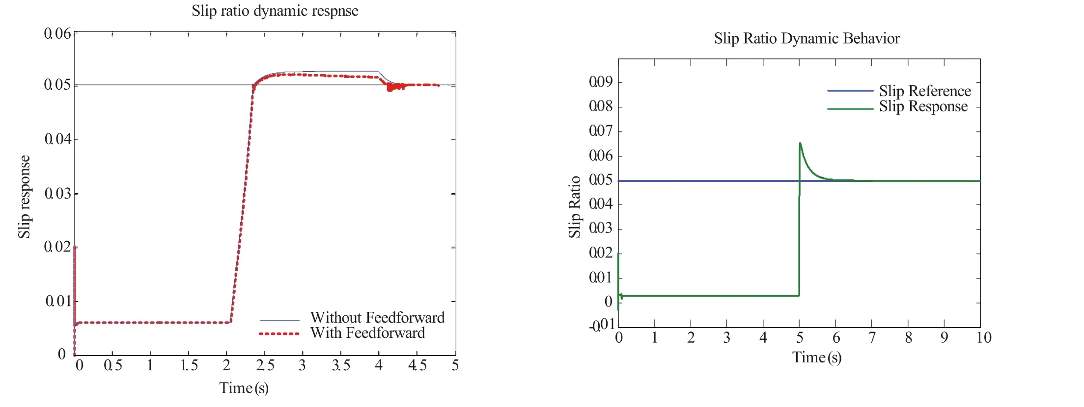
Fig.7. Control effectiveness of the traction control
(2) From the point of view of the feedback control, the added feedforward control can compensate the measurable disturbances timely, which helps reduce the burden of feedback control and improve the system stabilization. The feedforward compensation does not change the characteristic equation of the closed loop, so it has no influence on the system stability.
Fig.7 shows the control effectiveness of the traction control scheme. Left figure shows the vehicle running on the icy road as a special case. The command from drivers on the accelerator pedal changes in the form of ramp input. The optimal slip ratio reference is set as 0: 05. The tracking slip ratio is not increasing with the increase in drivers’demanded torque, and fi nally stabling at the optimal set value without severe ripples in the slip behaviors. Right figure shows the behaviors of the slip ratio under a sudden road change from high to low adhesion road surface at . The fi nal slip ratio tracks the given slip ratio immediately, consequently the wheel spin is prevented.
3.3 Regenerative Braking Control
Regenerative braking technology was fi rst introduced in electric locomotives, which can recover energy during deceleration. However there still remain challenges in regenerative braking, as which has to face and overcome many difficulties, such as the drive motor performance, battery performance, the drive system controller performance and the vehicle controller performance, etc. Therefore, much effort has been devoted to such technology, and various problems associated with them have been extensively studied in the literature.
Most of the regenerative braking systems mentioned above use both the electrif i ed braking and the friction braking with a cooperated mechanism. Gao and co-workers in Texas A&M University, proposed a neural network method for regenerative braking, and analyzed the energy recovery eff i ciency under driving cycle conditions[14]. Furthermore, based on feedback control strategy, they provided ABS systems for pure electric vehicle and hybrid vehicle. A braking simulation model is considered here to maximize braking energy in different braking cases[15-17]. Then, Honda Company of Japan developed hybrid electric vehicles and pure electric vehicles, named Insight and Plus, respectively. By increasing the regenerative braking and controlling friction braking, it can be found that the obtained result is better. Also, the research group in Flemish Institute of Technology established HEVAN, which is a platform for hybrid electric vehicle, to reserve dynamic energy by regulating brushless DC motors and induction motors. It can be seen that the efficiency of energy recovery for AC motor at low speeds is greater than for PMDC. In addition, the researchers in University of California presented the PHEV system equipped with a brake energy recovery. It is shown in simulations that the cost of energy with PHEV is about 18% less than other systems[18]. The authors proposed a fuzzy regenerative braking strategy for electric vehicles extending the driving range signif i cantly[19].
Pure electrified braking system can acquire the maximum available friction force and the kinetic energy recovery as much as possible due to the advantages of electric actuators. However, some challenges such as the battery SoC constraints, the hard braking at low speed using electrical torque, impedes the practical application of pure electrif i ed braking system. Novel structure and configurationneed to be explored to solve such problems. Using DC-DC and capacitor as a supplement to the energy storage system is a possible solution to be free of the SoC constraints. Furthermore, the pure distributed propulsion configuration using in-wheel or sidewheel motors can provide sophisticated and enough electrif i ed braking forces. Fig.8 shows two possible vehicle prototype configurations to meet the fullelectrif i ed-braking structure with electromechanical decoupling, where the grey box are the motors.
The dynamic equation of the wheel is expressed as:

Here, Mbis the braking force provided by the motor in generating state. The wheel starts to decelerate under the motor braking force. The dynamic equation of the vehicle speed reduction in the tire-ground friction force is:

Here, the friction is related to the side load expressed in one friction coeff i cient:

The slip ratio during the braking state is def i ned as:


Fig.8. EV conf i guration for fully electrif i ed regenerative braking
Apparently, the slip ratio during braking is negative and reaching-1 in wheel locking status. As for certain tire ground contact condition, the maximum ground friction braking force is less than the tire ground contact friction. When the slip ratioduring the braking control wheel is in the optimal slip ratio, the ground friction force has highest eff i ciency and shortest braking distance.
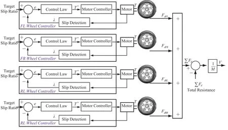
Fig.9. Control scheme of four-wheel-independently-braking system

Fig. 9 depicts a control scheme of four-wheel independently-braking configuration. The adopted control strategy is described as: through realtime adjustment of the motor braking force on each wheel, the slip ratio can be controlled around the vicinity of the optimal slip ratio so as to obtain the largest friction force on each wheel. Hence the vehicle will possess the maximum friction (ground braking force), with maximum deceleration and shortest braking distance.
During the process of rapid braking control, the braking force for motor control is actually the control of motor generating state, thus transferring part of the dynamic energy to the super capacitor and battery for energy recovery. It should be noted that the recovered energy is quite massive without the energy consumption in mechanical friction braking.
There are two key problems to be solved during the full electrif i ed braking control. One is to identify the tire-road contact conditions, such as the optimal slip ratio, which is used as the optimal braking control reference information. The other is to deal with the uncertainty, nonlinearities during braking process. In this regard, traction control method can be used to identify the tire pavement contact via motor electrical information.
4 Predictive Driving Control of Electric Vehicles for Energy Saving
Traff i c preview information is very useful for electric vehicles (EVs) for their energy saving. The driving operation of the electric vehicles involves energy distribution among hybrid components, the state of the battery SOC (state-of-charge), the braking energy recovery and safety issues. Jian et al.[20]demonstrated the energy saving driving requirement and awareness for the drivers in eleven European countries, including how to avoid congested routes and red lights parking driven technology.
The basic theory of global optimal control strategy for EVs is based on a specif i c condition to pre-def i ne the state of the motors, engines, batteries and other possible states of the vehicle. The global optimal methods include linear programming, DP (Dynamic programming) regulation, Markov and maximum likelihood, model predictive control, support vector machine (SVM), neural netwok, fi lter and Bellman dynamic programming and so on[21,22]. However, due to computational complexity and large data, these methods may not be applicable in real-time applications.
Currently, the vehicle telemetry such as the Global Positioning System (GPS) and the Geographical Information System (GIS) are actively used to predict the traffic preview information[23-26]. The information is provided periodically and it may include a preview length, a maximum speed prof i le and a minimum speed profile over the preview length[27]. In this section, a predictive driving control scheme of EVs is proposed, in which an EV searches for a driving route within the predicted maximum speed profile and minimum speed profile that minimizes the total electric energy consumption of the EV. Here, it should be guaranteed that the vehicle reaches the desired location at the desired time. The control concept of this control scheme is illustrated in Fig. 10. This fi gure is for one prediction horizon.
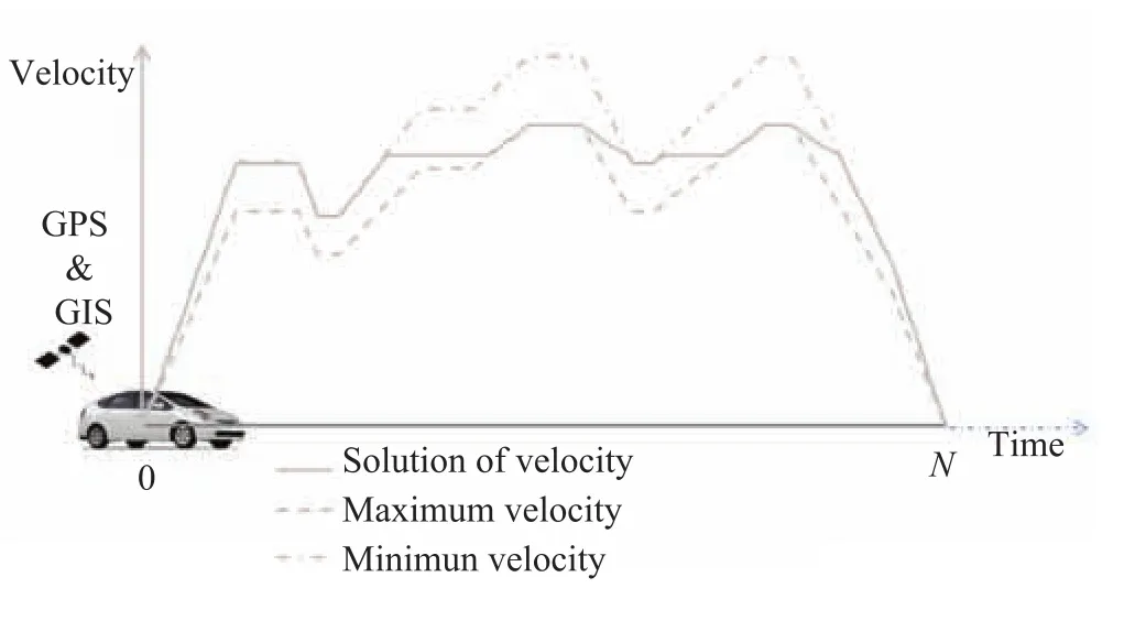
Fig.10. Driving route searching based on traff i c preview information
The control problem for one prediction horizon is formulated here. In this control problem, the state equation is as follows, which represents the vehicle dynamic behavior.

Here, the vehicle speed vvehis the state variable, and the vehicle acceleration avehis the control variable. The performance measure to be minimized is the total electric energy of the EV, as follows:

The control objective is to find a avehtrajectory over the prediction horizon to make the EV follow a vvehtrajectory which minimizes the total energy consumption of the EV while satisfying the constraints in Eq. (14).
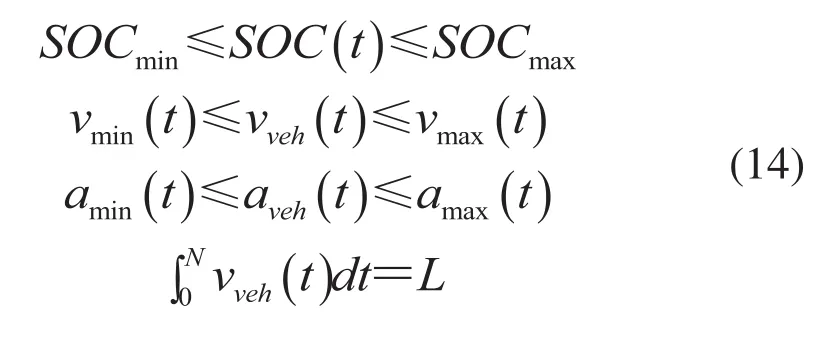
Here, SOC is the battery state of charge. vmin, vmaxand L are the predicted minimum speed, maximum speed, and preview length, respectively. aminand amaxare respectively obtained from vmin, vmaxand current vehicle speed.
The traffic preview information can be provided at every time step. After obtaining the solution for a prediction horizon, only the first element of the solution is taken for current time step k[28]. At next time step k+1, the same process is repeated and at the rest of time steps as well. Finally, the solution trajectory can be derived for all time steps. Here, one time step is the control period. This process is illustrated in Fig. 11.
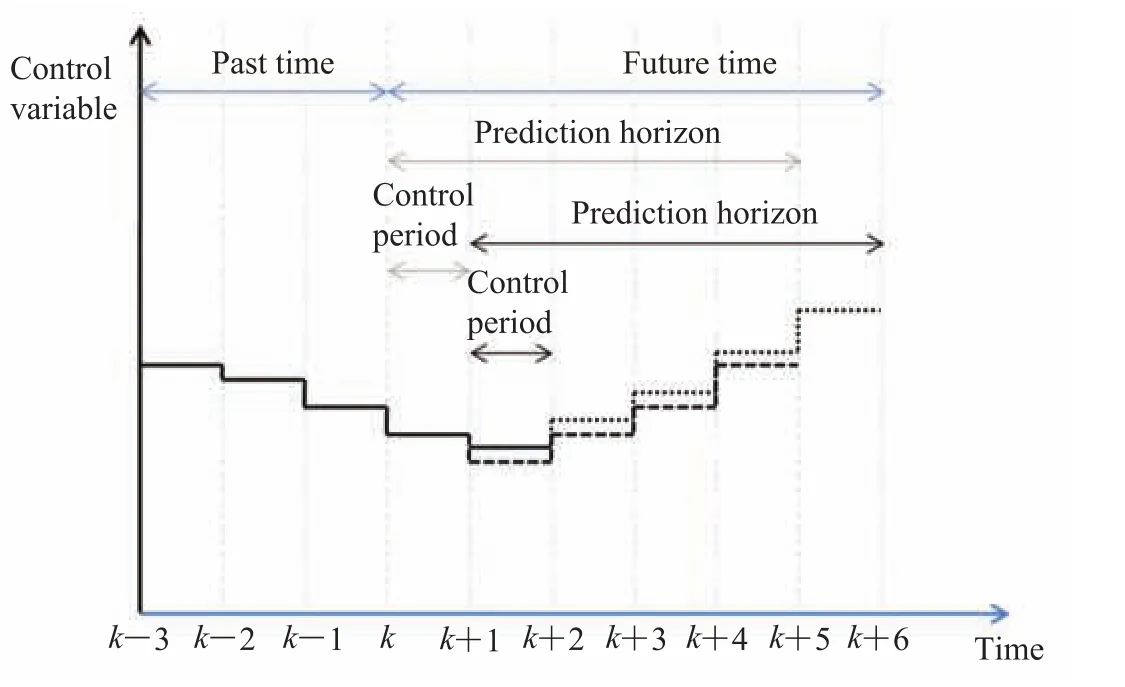
Fig.11. Control concept of the predictive control scheme
5 Intelligent Driving Strategies
Although a lot of passive and active assisting equipments have been installed, such as safety airbag, anti-slid agency, intelligent chip tires, and anti-lock braking system, they have obvious disadvantages with high cost and neglected perception and decision-making capability. Visual based active assist driving system is one of the most efficient applied technologies to decrease traffic accident rate. It can be easily installed with low cost and provide lane deviation alarm, blind spot detection, pedestrian recognition and danger precaution.
5.1 Driving Control Strategy
Vision technology is widely used in path recognition because images contain abundant information with low storage costs. Currently, there are two main methods for path identification: image feature method and model matching. The calculation of image feature method is rather simple with the aid of image segmentation and image classification techniques. But the lighting variations, shade occlusion, noise, road boundaries and marking lines such discontinuous factors would bring serious disturbance for the method application.
How to reduce the impact of surface water on lane detection and increase the accuracy and adaptability via symmetrical characteristics of lane markings is an important research direction. Xu et al.[29]proposed a lane detection system under bad weather conditions (i.e., rainy) based on the surface water reflection model and parallelism characteristics of the lanes. It can effectively improve the accuracy and stability for lane detection (Fig. 13). The proposed lane marking characteristics is calculated as:
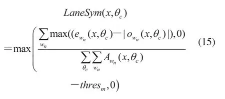
The definition of the variables in Eq. (15) can be found[29]. Moreover, disturbance on road such as trees, shades will increase the diff i culties in lane detection. Multiple methods should be combined to eliminate the disturbance and increase the reliability[30,31].

Fig.12. The diminishing points detection during line detection model
Liu et al.[32]analyzed the lane change control strategy and gave the dynamic model to predict the turning path. Based on this model, various scenarios for lane change and driving strategies have been analyzed for their danger level estimation. A monocular camera was used to calculate the risk level of all objects in the current driving scenarios based on resistance line alarm prediction method[33,34].
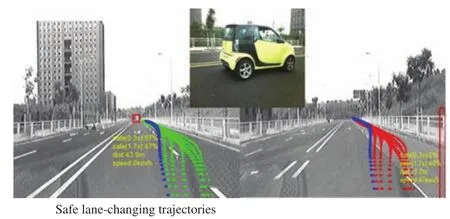
Fig.13. The line detection model during driving
Path planning and collision avoidance should also be considered during driving. By the use of high flexibility, high maneuverability advantages in the independent driven steering vehicles, it can accomplish the motion planning before collision so as to decrease collision opportunities. A collision avoidance path is determined before the collision and model prediction methods are used to control the steering and torque of each wheel to achieve the collision avoidance and path tracking[3,35].
5.2 Automatic Driving Technologies
With the development of intelligent transportation technologies, autopilot technology has been gained more attention because of its high safety, optimal route planning, time saving and low carbon dioxide emissions[30]. Vehicle motion states include such basic variables as the vehicle speed, acceleration,steering angle, and they can be acquired through additional independent sensors or CAN bus. Global Position System (GPS) is used to provide speed and heading angle measurements, so the acceleration can be calculated through differential equations. Automatic route planning and control strategy will be used to control the vehicles to reach the destination safely. The adaptive automatic driving technology can realize the energy saving through real-time environmental conditions and vehicle motion feature, which can also help to improve the traff i c congestion situations.
6 Human-Machine Interaction and Human Care for Drivers
Development of automotive technology is driven by social and human consumption demand. Cars have become an everyday essential transportation tool. Currently, improving driving safety and comforts becomes the main characteristics of automotive electronic systems. With the availabity of the driver’s driving behavior and driving condition can be monitored and assessed in real time. Determining the driver’s driving ability, the accidents can be avoided because of the driver’s operation errors. Driving safety will be improved signif i cantly by helping the driver to choose the right driving motor operation and reducing driver’s physical exertion. U.S. security scientist Heinrich’s survey results show that most accidents are caused by people’s unsafe behavior, which is determined by the person’s physical, psychological, environmental and genetic factors.
There are many factors that can cause adverse physiological and psychological reactions of drivers. Driving is a complex work, it can make driver fatigue easily and result in reduced sensitivity to judgement or even make a misjudgment. The general chronic disease and mild symptoms disease can reduce the driver’s hearing, touch, smell and physical reaction speed. The driver’s perception of space, light and roads will be relatively weak, prone to operator error, which can easily lead to accidents. When the driver’s psychological and emotional conditions change dramatically, the driver can not control his thinking activity and the ability to judge. Thus it is very important to monitor the driver’s physical and mental condition. It can alert the driver to stop driving and prevent the occurrence of accidents, when the driver is unwell by monitoring the driver’s heart rate cardiovascular function, fatigue and physical health status.
How to perform a more convenient and safer human-machine interaction and human care during driving is the key to solving this problem[1,35]. It involves computer science, psychology, cognitive science, linguistics, ergonomics and sociology such disciplines. Using voice, images and projection display technologies, it could achieve fast communication between people and cars for information interaction, including vehicles to road, vehicle to vehicle and vehicle to infrastructure.
It is very important to monitor the driver’s behaviors for driving safety. Heart rate, blood pressure and respiratory rate are the best indicator of the physiological parameter information of driver’s physical and mental status. Contact measurement such as electrocardiogram(ECG) will cause inconvenience to the measurement and discomfort to the driver, while non-contact heart rate detection brings convenience to the driver. Recently, there have been methods for noncontact measurementof heart rate and respiratory rate including laser Doppler[37], microwave Doppler radar[38], and thermal imaging[39,40], but these systems are very expensive and require complex hardware. Another method for noncontact measurement of heart rate and respiratory rate is using webcam[41].
Using webcam is a very promising method for driver, because it is very cheap and easy to achieve. In our research projects we used a webcam to measure the driver’s heart rate and respiratory rate for monitoring driver’s mental activity in real time. Using video, image processing and computer vision techniques, based on the photoplethysmography and blind source separation methods, we can achieve non-contact measurement of human heart rate and respiratory rate to warn the driver when combined with the physical state of the driver fatigue to warn for the driver. Fig. 14 shows the heart rate and respiratory rate measurement system in real time. It mainly consists of four parts, video display and collection, RGB raw average display, the results display after ICA and FFT and calculating results display in real time.
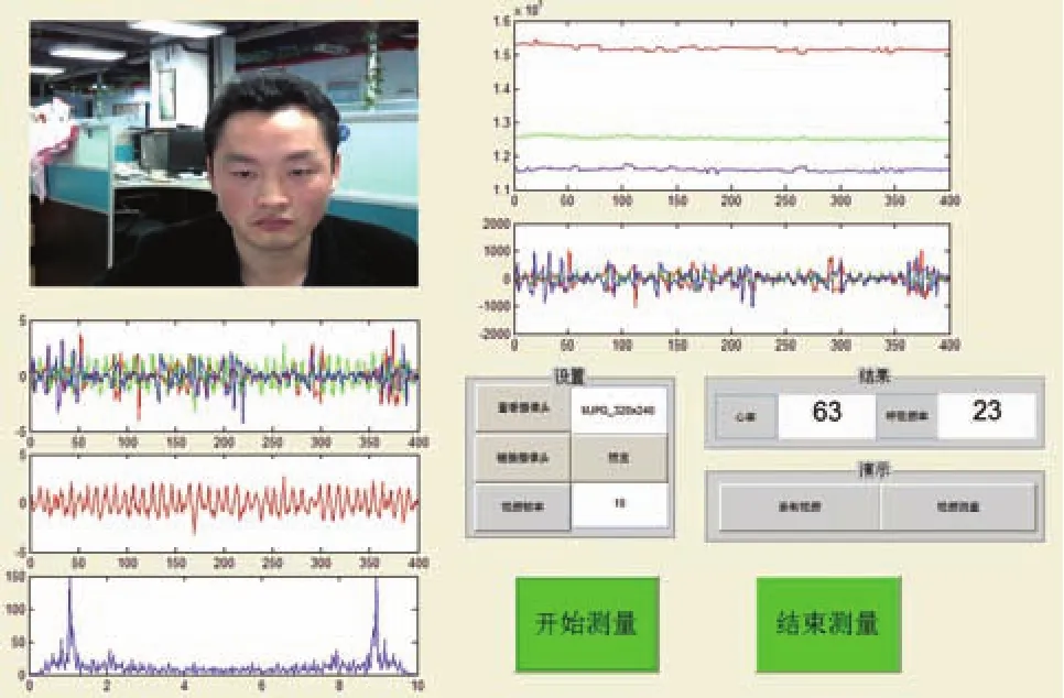
Fig.14. The heart rate and respiratory rate measurement system in real time
But monitoring is only a means, not an end. When we get the driver’s many parameters of the driver, assessment and proper regulation become very important. The positive regulation technology includes machine voice, chairs transform, environment (temperature, humidity, air) changing and so on. In summary, human-machine interaction and human care system is a complete system. The following chart illustrated in Fig. 15 can be used to represent.
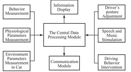
Fig.15. The chart of the human-machine interaction and human care system for driver
6 Conclusion and Discussions
In this paper, a method for estimating the vehicle motion parameters (including slip rate and friction coeff i cient of the ground) based on motor signals has been proposed, and electromechanical decoupling is implemented to the dynamics control of EV. As a result, the speed of control response could be much faster than traditional electromechanical coupling drive structure. This is of great significance for ensuring and improving the safety of EV.
We have introduced the structures of power system and dynamics control system based on electromechanical decoupling, and developed the traction control system and energy recovery braking control system of EV. Employing full brake energy in EV is proved feasible and safe.
By using full braking energy recovery and driving energy-saving control technology, the total energy efficiency of EVs can be greatly improved. It has a groundbreaking impact on the popularization of EVs, especially at the time when they are facing the bottleneck of battery energy density.
We also studied driving safety aids and humanfriendly technology, for improving the pleasure and comfort of driving from a technical perspective. The combination of EV and robot intelligent technology will be an important direction of automobile development in the future.
Acknowledgment
The authors would like to thank Dr. Rui Zhang, Ms. Feiyan Qin and Mr. Ming Wang, the research staff of the Automotive Research Center in the Shenzhen Institutes of Advanced Technology Chinese Academy of Sciences. This work is supported under the Shenzhen Science and Technology Innovation Commission Project Grant Ref. JCYJ20120615125931560.
[1] Chan CC. The state of the art of electric, hybrid, and fuel cell vehicles [C] // Proceedings of the IEEE, 2007, 95(4): 704-718.
[2] Zhou Y, Xu G, Qin F, et al. The prospect of smart cars: intelligent structure and human-machine interaction [C] // IEEE Conference on Robotics and Biomimetics, 2013: 1899-1904.
[3] Xu G, Liu L, Song Z. Driver behavior analysis based on bayesian network and multiple classif i ers [C] // International Conference on Information Systems, 2010: 663-668.
[4] Hori Y, Toyoda Y, Tsuruoka Y. Traction control of electric vehicle: basic experimental results using the test EV UOT Electric March [J]. IEEE Transactions on Industry Applications, 1998. 34(5): 1131-1138.
[5] Nam K, Oh S, Fujimoto H, et al. Robust yaw stability control for electric vehicles based on active front steering control through a steer-by-wire system [J]. International Journal of Automotive Technology, 2012, 13(7): 1169-1176.
[6] Yuan XB, Wang JB. Torque distribution strategy for a front-and rear-wheel-driven electric vehicle [J]. IEEE Transactions on Vehicular Technology, 2012, 61(8): 3365-3374.
[7] Yin GD, Jin XJ. Cooperative control of regenerative braking and antilock braking for a hybrid electric vehicle [J]. Mathematical Problems in Engineering, 2013.
[8] Xu G, Xu K. Novel estimation of tyre-road friction coeff i cient and slip ratio using electrical parameters of traction motor for electric vehicles [J]. International Journal of Vehicle Autonomous Systems, 2013, 11: 261-278.
[9] Colli VD, Tomassi G, Scarano M. “Single wheel”longitudinal traction control for electric vehicles [J]. IEEE Transactions on Power Electronics, 2006, 21(3): 799-808.
[10] Yamazaki H, Nagai M, Kamada T. A study of adhesion force model for wheel slip prevention control [J]. JSME International Journal Series C-Mechanical Systems Machine Elements and Manufacturing, 2004, 47(2): 496-501.
[11] Colli VD, Marignetti F, Di Stefano R, et al. Traction control for a PM axial-f l ux in-wheel motor [C] // 2006 12th International Power Electronics and Motion Control Conference, 2006, (1-4): 591-596. [12] Hu JS, Yin D, Hori Y, et al. A new mtte methodology for electric vehicle traction control [C] // 2009 International Conference on Electrical Machines and Systems, 2009: 1666-1671.
[13] Hu JS, Yin D, Hori Y, et al. Electric vehicle traction control: a new mtte methodology [J]. IEEE Industry Applications Magazine, 2012, 18(2): 23-31.
[14] Gao Y, Chu L, Ehsani M. Design and control principles of hybrid braking system for EV, HEV and FCV [C] // IEEE Vehicle Power and Propulsion Conference, 2007: 384-391.
[15] Gao H, Gao Y, Ehsani M. A neural network based SRM drive control strategy for regenerative braking in EV and HEV [C] // IEEE International Electric Machines and Drives Conference, 2001: 571-575.
[16] Gao Y, Ehsani M. Parametric design of the traction motor and energy storage for series hybrid off-road and military vehicles [J]. IEEE Transactions on Power Electronics, 2006, 21(3): 749-755.
[17] Yuan X, Gao YM, Ehsani M. Study on the performance and control of SR machine for vehicleregenerative braking [C] // IEEE Conference of Vehicle Power and Propulsion, 2008: 1-5.
[18] Francisco A, Frank A. Plug-in hybrid electric vehicles with full performance from sports cars to full sized trucks [C] // The 18th International Electric Vehicle Symposium, 2001.
[19] Xu G, Li W, Xu K, et al. An intelligent regenerative braking strategy for electric vehicles [J]. Energies, 2011, 4(9): 1461-1477.
[20] Jian L, Xue H, Xu G, et al. Regulated charging of plug-in hybrid electric vehicles for minimizing load variance in house-hold smart microgrid [J]. IEEE Transactions on Industrial Electronics, 2013, 60(8): 3218-3226.
[21] Chen Y, Wang J. Fast and global optimal energyeff i cient control allocation with applications to over-actuated electric ground vehicles [J]. IEEE Transactions on Control Systems Technology, 2012, 20(5): 1202-1211.
[22] Zhou Y, Dexter A. Off-line identif i cation of nonlinear, dynamic systems using a neuro-fuzzy modelling technique [J]. Fuzzy sets and systems, 2013, 225: 74-92.
[23] Amditis A, Andreone L, Pagle K, et al. Towards the auto-motive HMI of the future: overview of the AIDE-integrated project re-sults [J]. IEEE Transactions on Intelligent Transportation Systems, 2010, 11(3): 567-578.
[24] Kim TC, Watson MH. Fuel economy benef i ts of look ahead capability in a mild hybrid conf i guration [C] // IFAC World Cogress, 2008.
[25] Manzie C, Watson H, Halgamuge S. Fuel economy improvements for urban driving: Hybrid vs. intelligent vehicles [J]. Transportation Research Part C: Emerging Technologies, 2007, 15(1): 1-16. [26] Manzie C, Kim TS, Sharma R. Optimal use of telemetry by parallel hybrid vehicles in urban driving [J]. Transportation Research Part C: Emerging Technologies, 2012, 25: 134-151.
[27] Ngo DV, Hofman T, Steinbuch M, et al. An optimal control-based algorithm for hybrid electric vehicle using preview route information [C] // American Control Conference, 2010: 5818-5823.
[28] Ripaccioli G, Bernardini D, Cairano S, et al. A stochastic model predictive control approach for series hybrid electric vehicle power management [C] // American Control Conference, 2010: 5844-5849.
[29] Xu G, Liu L, Ou Y, et al. Dynamic modeling of driver control strategy of lane-change behavior and trajectory planning for collision prediction [J]. IEEE Transactions on Intelligent Transportation Systems, 2012, 13(3): 1138-1155.
[30] Sun Z, Bebis G, Miller R. On-road vehicle detection: a review [J]. IEEE Transactions on Pattern Analysis and Machine Intelligence, 2006, 28(5): 694-711.
[31] Xu J, Chen G, Xie M. Vision-guided automatic parking for smart car [C] // IEEE Intelligent Vehicles Symposium, 2000: 725-730.
[32] Liu L, Xu G, Song Z. Driver lane changing behavior analysis based on the parallel bayesian networks [C] // The 6th International Conference on Natural Computation, 2010: 1232-1237.
[33] Gressmann M, Palm G, Lohlein O. Surround view pedestrian detection using heterogeneous classif i er cascades [C] // The 14th International IEEE Conference on Intelligent Transportation Systems, 2011: 1317-1324.
[34] Wang R, Wang J. Fault-tolerant control with active fault diagnosis for four-wheel independently-driven electric ground vehicles [J]. IEEE Transactions on Vehicular Technology, 2011, 60(9): 4276-4287.
[35] Leon LC, Hirata R. Vehicle detection using mixture of deformable Parts Models: Static and dynamic camera [C] // The 25th SIBGRAPI IEEE Conference on Graphics, Patterns and Images, 2012: 237-244.
[36] Wang W, Bubb H. A theoretical framework for ecological function allocation in human-machine interface [C] // International Symposium on Knowledge Acquisition and Modeling, 2008: 257-261.
[37] Ulyanov SS, Tuchin VV. Pulse-wave monitoring by means of focused laser beams scattered by skin surface and membranes [C] // Proceedings of SPIE, Static and Dynamic Light Scattering in Medicine and Biology, 1993, 1884:160-167.
[38] Greneker E. Radar sensing of heartbeat and respiration at a distance with applications of the technology [C] // Proceedings of RADAR Conference, 1997: 150-154.
[39] Fei J, Pavlidis I. Thermistor at a distance: unobtrusive measure-mentof breathing [J]. IEEE Transactions on Biomedical Engineering, 2009, 57(4): 988-998.
[40] Garbey M, Sun N, Merla A. et al. Contact-free measure-ment of cardiac pulse based on the analysis of thermal imagery [J]. IEEE Transactions on Biomedical Engineering, 2007, 54(8): 1418-1426.
[41] Poh M, McDuff DJ, Picard R. Advancement in noncontact, multiparameter physiological measurement using a webcam [J]. IEEE Transaction on Biomedical Engineering, 2011, 58(1): 7-11.
The Prospect of Electric Vehicles: Pure Electrif i cation, Intelligence and Human Care
XU Guoqing1,2XU Kun2ZHANG Qi2ZHENG Chunhua2LIANG Jianing2ZHOU Yimin2
1( The Department of Mechanical and Automation Engineering, the Chinese University of Hongkong, Hongkong 999077, China )
2( Shenzhen Institutes of Advanced Technology, Chinese Academy of Sciences, Shenzhen 518055, China )
In this paper, a new concept of fully electrif i ed vehicles, based on the principle that the braking energy can be fully recovered via electrical motor and active safety control so as to improve energy eff i ciency greatly, was proposed. It reveals that this type of vehicles possesses the characteristics of perception for vehicle motion behaviour and the related intelligent detection methods were also introduced. At the same time, the dynamic control structure of the mechanicalelectrical decoupling in the vehicles was also discussed. Furthermore, the strategy of energy-saving, human-machine interaction, assistant driving and human care technologies were illustrated as well.
full-electrif i cation; traction control; regenerative braking; energy management; human care
U 469.72
A
2013-11-20
Xu Guoqing, Ph.D., Professor, Chief designer and chief scientist of R&D Center for Electric Vehicle, CAS. His research interests include electric vehicle and control, energy converter and control and intelligent technologies, etc.; Xu Kun(corresponding author), Ph.D. candidate. His research interests include advanced motion control for electric vehicles and robots, E-mail: kun.xu@siat.ac.cn; Zhang Qi, Ph.D., Assistant Research Professor. His research interests are signal processing, biomedical sensor measurement and control theory; Zheng Chunhua, Ph.D., Assistant Research Professor. Her research interests are energy management in pure electric vehicles and hybrid electric vehicles; Liang Jianning, Ph.D., Associate Research Professor. His research interest is the motor control; Zhou Yimin(corresponding author), DPhil, Associate Research Professor. Her research interests are the control theory, sensor optimization and motor control, E-mail: ym.zhou@siat.ac.cn.
