Steam Reforming of Dimethyl Ether by Gliding Arc Gas Discharge Plasma for Hydrogen Production*
2014-07-18WANGBaowei王保伟SUNQimei孙启梅Yijun吕一军YANGMeilin杨美琳andYANWenjuan闫文娟
WANG Baowei (王保伟)**, SUN Qimei (孙启梅), LÜ Yijun (吕一军), YANG Meilin (杨美琳) and YAN Wenjuan (闫文娟)
Key Laboratory for Green Chemical Technology, School of Chemical Engineering Technology, Tianjin University, Tianjin 300072, China
Steam Reforming of Dimethyl Ether by Gliding Arc Gas Discharge Plasma for Hydrogen Production*
WANG Baowei (王保伟)**, SUN Qimei (孙启梅), LÜ Yijun (吕一军), YANG Meilin (杨美琳) and YAN Wenjuan (闫文娟)
Key Laboratory for Green Chemical Technology, School of Chemical Engineering Technology, Tianjin University, Tianjin 300072, China
Gliding arc gas discharge plasma was used for the generation of hydrogen from steam reforming of dimethyl ether (DME). A systemic procedure was employed to determine the suitable experimental conditions. It was found that DME conversion first increased up to the maximum and then decreased slightly with the increase of added water and air. The increase of total feed gas flow rate resulted in the decrease of DME conversion and hydrogen yield, but hydrogen energy consumption dropped down to the lowest as total feed gas flow rate increased to 76 ml·min−1. Larger electrode gap and higher discharge voltage were advantageous. Electrode shape had an important effect on the conversion of DME and production of H2. Among the five electrodes, electrode 2#with valid length of 55 mm and the radian of 34 degrees of the top electrode section was the best option, which enhanced obviously the conversion of DME.
dimethyl ether, steam reforming, hydrogen production, gliding arc gas discharge
1 INTRODUCTION
It is well known that fossil energy is physically limited and the world of today is characterized by a rapid growth in energy utilization. Therefore, more and more attention has been focused on the exploitation and utilization of alternative clean fuels. Hydrogen is considered a clean energy source which provides a considerable quantity of thermal energy per unit mass and has no emission of CO2. Dimethyl ether (DME) is an excellent resource for hydrogen production with its high H/C ratio and high-energy volumetric density. DME has several advantages concerning environmental and health aspects such as non-toxicity, and biological degradation. And it burns without producing soot because of no carbon-carbon bonds, which makes it very interesting as a fuel alternative. Also, DME was liquid in the low pressure similar to liquefied petroleum gas (LPG), thus can be stored and transported using the facilities providing LPG. Furthermore, the preparation of DME has many raw material sources [1, 2]. Therefore, hydrogen production from DME reforming has attracted the attention of home and abroad researchers. Researches on hydrogen production through DME reforming including steam reforming [3-6] and partial oxidation [7-11] have been reported in many previous studies, and of which, plasma processes [6, 10, 11] provide significant advantages in terms of fast reactions and energy efficiency.
Plasma is employed to produce high reactive particles with high energy through electronic and ionic collisions, and then immediately induces subsequent chemical reactions under ambient temperature and atmospheric pressure. The production of H2from DME has been investigated in a wide range of plasma processes including dielectric barrier discharge [12-14], corona discharge [6, 10, 15, 16], spark discharge plasma [11] and other plasma systems [17]. Zou et al. [6, 10, 16] studied hydrogen production from DME decomposition, DME steaming reforming and DME partial oxygen reaction using corona discharge plasma. The result showed that addition of water and oxygen was more advantageous for DME conversion. Alternating current (AC) especially sine wave corona discharge was more effective than DC corona discharge in DME decomposition and hydrogen production. Song et al. [11] studied the partial oxygen reaction of DME for hydrogen production using spark discharge plasma, and investigated the influences of several parameters such as supply voltage, electric arc frequency, air/DME ratio, DME feed flow rate and discharge arc length. Ma and Li [17] also studied the DME partial oxidation reaction using self-made three-chambers-in-series plasma generator, and had investigated the influence of operation parameters and structure parameters, electrode materials and electrode heat dissipation characteristics on the production of hydrogen.
Although gliding arc plasma is classified as non-thermal plasma, it has some characteristics of thermal plasma. Gliding arc gas discharge (GRD) plasma integrates non-thermal plasma and thermal plasma advantages, which is more favorable at lower current intensity, higher electron density and higher injection flow rate compared to other types of non-thermal plasma. At present its applications have already obtained a better effect in large-scale volatile organic compounds processing [18, 19], greenhouse gas processing [20], surface modification [21, 22] and gas transformation [23-28], etc. It has become one of the hot spots in plasma research. Studies on methanereforming using GRD plasma including using GRD reactor [23, 24], GRD-catalyst reformer [25], a multistage GRD system [26] and AC microsized GRD [27] have been reported many times. Meanwhile, alcohol reforming with GRD plasma has been reported increasingly. Recently, Burlica et al. [29] has studied hydrogen production from sprays of alcohol solutions using pulsed GRD plasma. In our previous work [30], in which hydrogen was produced from DME conversion with gliding arc discharge plasma, the effects of the discharge parameters and process parameters on the DME conversion for hydrogen production were investigated. The results indicated that the mole ratio of Ar and DME fixed at about 23% was advantageous to DME conversion.
However, up to date hydrogen production from DME reforming using GRD plasma is still surprisingly scarce in the literature, and deserves further research. The goal of the work reported in this paper was to present the use of GRD plasma as an alternative to carry out the reforming of DME at atmospheric pressure and lower temperature. The influence of several experimental parameters on the conversion of DME, the yield and generation rate of H2as well as energy consumption of hydrogen formation has been studied to quest for the optimum experimental conditions.
2 EXPERIMENTAL
2.1 Reagents and apparatus
Reagents: High purity argon (>99.99%, Beijing Beifen Gas Industry Co.), DME (>99%, Hebei Kaiyue Group), air (Tianjin Liufang Gas Industry Co.).
Apparatus: Gliding arc reactor (self-made, 110 mm long, inner diameter φ 45 mm and 3 mm thick), D08-4C/ZM mass flow display device (Beijing Jianzhong Machinery Factory), D07-7A/ZMM MFC mass flow controller (Beijing Jianzhong Machinery Factory), CPT-2000K plasma generator (Nanjing Suman Electronic Technology Co.), HHS electric constant temperature water bath (Tianjin HuaBei Experimenting Co.), LML-1 wet gas flowmeter (Changchun Automobile Filter Co.), DPO2012 digital phosphor oscilloscope (Tektronix Co.), P6015A high-voltage probe, A622 current probe, FULI 9790 II gas chromatography (Zhengjiang Fuli Analytical Instrument Co.).
2.2 Experimental setup
The schematic diagram of the experimental set-up is shown in Fig. 1.
A laboratory scale gliding arc (GA) reactor was adopted as the plasma source, which consisted of two knife-shaped electrodes fixed on a glass enclosure with 45 mm inner diameter, 80 mm height and a nozzle with inner diameter of 0.1 mm. The electrode gap can be adjusted to suit the reaction conditions. The vertical distance between nozzle inlet and the electrode throat was 13 mm. Two electrodes were connected to a high AC voltage power supply providing a maximum power of 300 W, which supplied a roughly a sine wave AC with 19.0 kHz, voltage from 11.0-18.5 kV and peak current 2.0 A. High purity argon as carried gas and DME as reactant gas went to a mixer and their flow rates were precisely controlled by MFC respectively. Then the mixed gases and water were introduced into the electrode throat to generate the hydrogen-rich gases. Water volume content was controlled through changing the temperature of electric constant temperature water bath. Effluents were passed through a cool trap to condense non-converted reactants. The mixed gases were purged into the reactor for 1 h before the electric discharge started in order to evict the air from the reactor and avoid the oxidizing reaction.
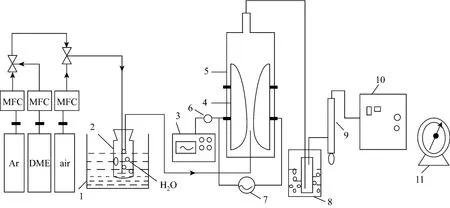
Figure 1 Schematic diagram of reaction1—electric constant temperature water bath; 2—jar; 3—oscilloscope; 4—electrodes; 5—glass tube; 6—high-voltage probe; 7—high voltage power supply; 8—cool trap; 9—bubble flowmeter; 10—gas chromatography; 11—wet gas flowmeter
The range of operating parameters was shown inTable 1. Among them, R, QAr-DME, d, U and xairwas defined as H2O/DME mole ratio, the Ar-DME mixed gas flow rate, electrode gap, discharge voltage and air volume fraction in Ar-DME-air mixed gas, respectively.

Table 1 Operational parameters and electrode geometry of the Ar-DME system
The electrode shape and geometry size of the five electrodes are shown in Fig. 2.
2.3 Analytical methods
The main components in gas mixture were measured using a gas chromatography (GC9790II) with thermal conductivity detector and He carrier. TDX-01 packed column (3 m×3 mm, Lanzhou Institute of Chemical Physics, CAS, Lanzhou, China) was used for the composition analysis of H2, CO, CH4and CO2, and Hevy Seep DB packed column (2 m×3 mm, Lanzhou Institute of Chemical Physics) was used to analyze the concentrations of Ar and C2Hx, respectively.
DME conversion was defined as

The selectivity of hydrogen and carbon-containing materials (CO, CH4, and C2H2/C2H4) were calculated by Eqs. (2) and (3), respectively:
H2yield was calculated as

H2generation rate (G) was

The specific energy consumption (E) is defined as the energy consumed per ml hydrogen:

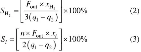
where Foutrepresents the outlet total gas flow rate (ml·min−1), q1and q2represent the inlet and outlet DME flow rate (ml·min−1),2Hx and xirepresent volume fraction rate of hydrogen and carbon-containingmaterials (CO, CH4, and C2H2/C2H4) in outlet total gas flow rate (%), n represents the carbon atom number in the hydrocarbon molecules, P represents discharge power (W).
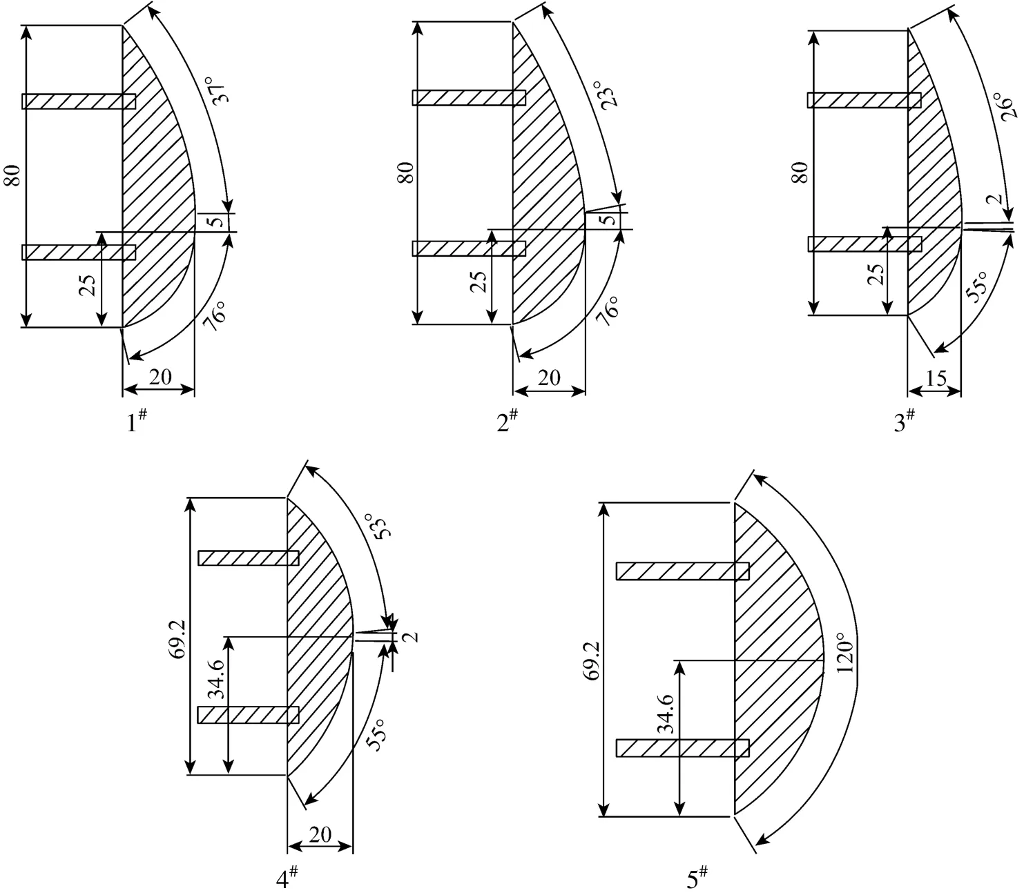
Figure 2 The knife-shaped electrode and geometry size

Figure 3 Effect of H2O/DME ratio on DME conversion and H2yield as well as gaseous products selectivities (electrode 2#, xDME/(Ar-DME)=23%, QAr-DME=43 ml·min−1, d=4 mm, U=17.1 kV, xair=0)1—DME conversion; 2—H2yield; 3—H2selectivity; 4—CO selectivity; 5—H2/CO ratio; 6—CH4selectivity; 7—C2H2/C2H4selectivity; 8—C2H6selectivity
3 RESULTS AND DISCUSSION
3.1 Effect of water/DME ratio
The effect of H2O/DME ratio on the DME conversion, hydrogen yield and the selectivities of gaseous products were shown in Fig. 3. As the inlet H2O/DME ratio rised up to 2.3, DME conversion and hydrogen yield increased up to the maximum of 73.2% and 40.7%, respectively. It is obvious that a lower H2O/DME ratio corresponds to a lower steam flow rate, thus residence time of H2O molecules increases. Oxygen radical and hydroxyl radical from water molecules become more active to transfer the energy and collide with DME molecules to promote its decomposition. When H2O/DME ratio increased to more than 2.3, DME conversion and hydrogen yield turned to decrease. The reason is that higher steam flow rate not only decreases residence time of the reactants and DME volume concentration in the total feed flow rate, but also increases the energy consumption on H2O decomposition. Additionally, too much water may deteriorate the discharge environment, which may lead to the decreasing DME conversion. CO and C2H2/C2H4selectivities increased first and then decreased slightly as the H2O/DME ratio rose. H2selectivity and H2/CO ratio increased continuously, suggesting that addition of H2O is in favor of DME decomposition and H2production. C2H6selectivity still stayed at a relatively low level. It’s worth mentioning that the carbon deposition reduced with increasing H2O/DME ratio.
Effect of H2O/DME ratio on products generation rates and E was shown in Table 2. It showed that H2, CO and C2hydrocarbons generation rates increased continuously as H2O/DME ratio rose from 0 to 2.3, CH4generation rate and E decreased slightly. It’s dueto that higher H2O/DME ratio increased H2selectivity, resulting in the lower energy consumption. When the H2O/DME ratio was more than 2.3, products generation rates decreased and E increased slightly. This can be explained that higher H2O/DME ratio could reduce the DME molecules conversion, and increase the energy consumption on H2O decomposition.

Table 2 Effect of H2O/DME ratio on products generation rates and E (electrode 2#, xDME/(Ar-DME)=23%, QAr-DME=43 ml·min−1, d=4 mm, U=17.1 kV, xair=0)
3.2 Effect of the electrode shape
The effect of electrode shape on DME conversion and hydrogen yield as well as the selectivity of gaseous products was shown in Table 3. It was seen that DME conversion, H2yield and H2, CO, C2H2/C2H4selectivities were much higher using electrodes 1#-3#than that using 4#and 5#. This is ascribed to the fact that the discharge arc was generated at the narrowest gap between two electrodes and further dragged by feed gas towards the top section direction. This determines the length of the electrode top section has a stronger effect on discharge space and residence time of the reactants within the gliding arc discharge zone than that of the electrode bottom section does, which is called the valid electrode length. Obviously, the valid electrode length in 1#-3#electrode was 55 mm much longer than 34.6 mm in 4#and 5#electrode, which directly increased the discharge space and residence time, and then increased the change of DMEconversion and hydrogen yield. DME conversion and hydrogen yield using electrode 2#were higher than that using 1#. The reason is that smaller radian of the electrode 2#top section increases the discharge arc length and discharge space, which increases the collision chances of DME molecules with high-energy electron, and then increases the number of DME molecules decomposed and active free radicals. Analogously, DME conversion, H2yield and H2, CO, C2H2/C2H4selectivities were much higher using the electrode 3#than that using 4#, which was verified by the results from Table 3. Obviously, the difference of vertical section length in the widest place of electrode 2#and electrode 3#is the main reason that DME conversion, H2yield and H2, CO, C2H2/C2H4selectivity using the electrode 2#was higher than that using the electrode 3#. From Table 3, it was most adverse for DME conversion using 5#electrode in comparison with other four electrodes. As shown in Table 3, the effect of electrode shape on the selectivities of H2, CO, C2H2/C2H4was contrary with the effects on CH4and C2H6selectivities. It indicates that C2H2/C2H4generation reaction is competitive with respect to generation of CH4and C2H6. Among the gaseous products, there is only a very small amount of C2H6.

Table 3 Effect of the electrode shape on DME conversion and H2yield as well as gaseous products selectivities (xDME/(Ar-DME)=23%, QAr-DME=43 ml·min−1, d=4 mm, U=17.1 kV, R=2.3, xair=0)
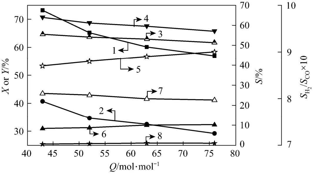
Figure 4 Effect of total feed flow rate on DME conversion and H2yield as well as gaseous products selectivities (electrode 2#, xDME/(Ar-DME)=23%, d=4 mm, U=17.1 kV, R=2.3, xair=0) 1—DME conversion; 2—H2yield; 3—H2selectivity; 4—CO selectivity; 5—H2/CO ratio; 6—CH4selectivity; 7—C2H2/C2H4selectivity; 8—C2H6selectivity
As shown in Table 4, a similar effect of electrode shape on gaseous product generation rates was also observed. It was seen that gaseous product (H2, COand C2hydrocarbons) generation rates were higher using electrodes 1#-3#in comparison with electrodes 4#and 5#. E was also lower when using electrodes 1#-3#, due to higher H2selectivity of the former.

Table 4 Effect of the electrode shape on gaseous products generation rates and E (xDME=23%, QAr-DME=43 ml·min−1, d=4 mm, U=17.1 kV, R=2.3, xair=0)
3.3 Effect of total DME-Ar feed flow rate
Effect of total feed flow rate on DME conversion and hydrogen yield as well as gaseous products selectivities was shown in Fig. 4. H2O/DME ratio and volume concentration of DME were fixed at 2.3 and 23%, respectively. Total DME-Ar feed flow rate waschanged within the range of 43 ml·min−1-76 ml·min−1. It is clear that DME conversion decreased from 73.2% to 56.9% and hydrogen yield decreased from 40.7% to 29.2% with increasing total DME-Ar feed flow rate. This was ascribed to the reduced residence time of reactants in the discharge zone. A similar effect of feed gas flow rate on the decreasing selectivities of gaseous products (H2, CO, C2H2/C2H4) was also observed. CH4selectivity curve was rising, in contrast with the effect of feed gas flow rate on C2H2/C2H4selectivity. The mainly reason is that it can easily generate ·CH3free radicals from CH3OCH3molecules ionization, when the residence time is long enough for ·CH3free radicals to be dissociated into·CH2and ·CH free radicals, and then combined into C2H2/C2H4molecules, which will result in the increasing of C2H2/C2H4selectivity. C2H6selectivity stayed a relatively low level. Under the studied conditions, the selectivity toward the production of hydrogen and carbon monoxide was kept increasing slightly.
Effect of total DME-Ar feed flow rate on products generation rates and E was shown in Table 5. It shows that products generation rates increased continuously as total feed gas flow rate rose. It is because that as total feed gas flow rate increases, more DME molecules are dissociated in the plasma region and further converted into hydrogen and hydrocarbons. Additionally, H2and CO generation rates increased more, and C2hydrocarbons generation rates increased less. It is due to that C2H2/C2H4generation needs more steps, and there is no enough time to complete the reaction with the decreasing residence time by increasing the total feed gas flow rate. E decreased as total feed gas flow rate rose, and reached the minimum (0.016 W·h·ml−1) at the highest H2generation rate.
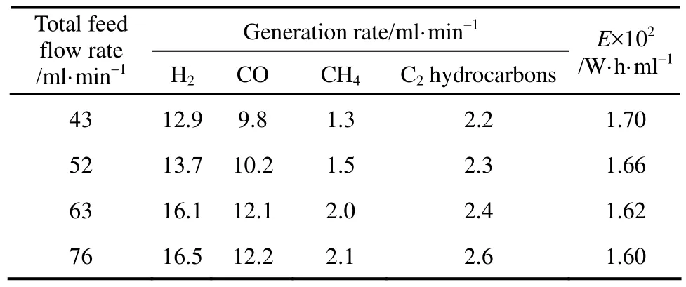
Table 5 Effect of total feed flow rate on products generation rates and E (electrode 2#, xDME=23%, d=4 mm, U=17.1 kV, R=2.3, xair=0)
3.4 Effect of discharge voltage
The effect of discharge voltage on DME conversion and hydrogen yield as well as the selectivity of gaseous products was shown in Table 6. The discharge voltage was changed in the range of 11.2 kV to 17.1 kV and cannot be increased further, since the discharged electrode will be connected with an electric arc if the voltage was too high. It is clear that DME conversion and hydrogen yield increased with increasing discharge voltage due to more energy input and more active radicals to promote the dissociation of DME. Based on above reasons, the selectivity of hydrogen and carbon monoxide as well as C2unsaturated hydrocarbons also increased with discharge voltage.
Effect of discharge voltage on gaseous products generation rates and E was shown in Table 7. Obviously, gaseous products generation rates trend was similar to the selectivity trend. It suggested that improving discharge voltage was very favorable for hydrogen production from DME decomposition using gliding arc plasma.
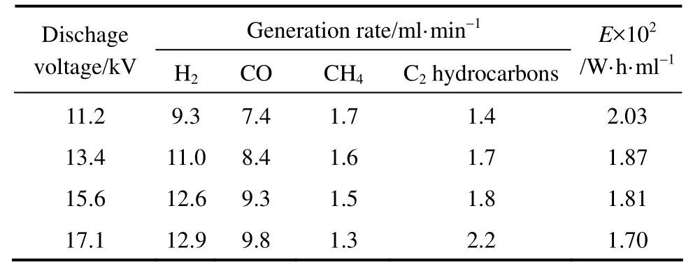
Table 7 Effect of discharge voltage on products generation rates and E (electrode 2#, xDME/(Ar-DME)=23%, QAr-DME=43 ml·min−1, d=4 mm, R=2.3, xair=0)
3.5 Effect of the electrode gap
The effect of the electrode gap was shown in Fig. 5. In this experiment electrode gap was changed from 2 mm to 4 mm. It is due to that larger electrode gap needs a higher breakdown voltage and working voltage. As the electrode gap was more than 4 mm, it becomes more difficult to maintain the discharge in a stable state when the discharge voltage is constant. From Fig. 5, it is obvious that DME conversion and hydrogen yield increased with the electrode gap. This can be explained by the increased discharge space andresidence time. H2, CO and C2H2/C2H4selectivity as well as H2/CO ratio for the selectivity increased with electrode gap. CH4selectivity showed a decreasing trend, supporting that the reaction producing C2H2/C2H4is competitive with that producing CH4.

Table 6 Effect of discharge voltage on DME conversion and H2yield as well as gaseous products selectivities (electrode 2#, xDME/(Ar-DME)=23%, QAr-DME=43 ml·min−1, d=4 mm, R=2.3, xair=0)
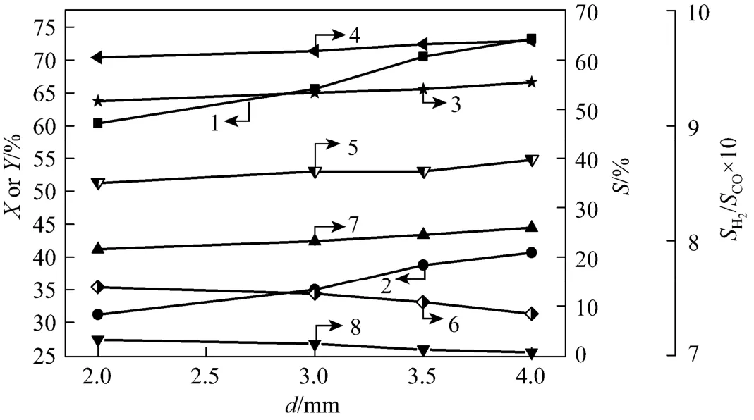
Figure 5 Effect of the electrode gap on DME conversion and H2yield as well as gaseous products selectivities (electrode 2#, xDME/(Ar-DME)=23%, QAr-DME=43 ml·min−1, U=17.1 kV, R=2.3, xair=0)1—DME conversion; 2—H2yield; 3—H2selectivity; 4—CO selectivity; 5—H2/CO ratio; 6—CH4selectivity; 7—C2H2/C2H4selectivity; 8—C2H6selectivity

Figure 6 Effect of addition of air on DME conversion and H2yield as well as gaseous products selectivities (the electrode shape 2#, xDME/(Ar-DME-air)=23%, R=2.3, QAr-DME-air=43 ml·min−1, d=4 mm, U=17.1 kV1—DME conversion; 2—H2yield; 3—H2selectivity; 4—CO selectivity; 5—H2/CO ratio; 6—CH4selectivity; 7—C2H2/C2H4selectivity; 8—C2H6selectivity
Analogously, H2, CO and C2H2/C2H4generation rates improved with increasing electrode gap. It is seen that larger electrode gap is favorable for DME conversion and hydrogen yield from Table 8. E reached the maximum when the electrode gap was the minimumof 2 mm. This is because that the shorter arc length and residence time result in the dissociation of DME molecules and various active radicals incompletely, and then the decrease of hydrogen production.

Table 8 Effect of the electrode gap on products generationrates and E (electrode 2#, xDME/(Ar-DME)=23%, QAr-DME=43 ml·min−1, U=17.1 kV, R=2.3, xair=0)
3.6 Effect of addition of air
Figure 6 showed the effect of addition of air on DME conversion and H2yield as well as gaseous product selectivities. Water/DME ratio was fixed at 2.3 and volume concentration of air was changed within the range of 0-31.7%. From Fig. 6, it is apparent that DME conversion and hydrogen yield were maximized to 74.1% and 43.4% respectively when volume concentration of air was 25.8%. H2, CO and C2H2/C2H4selectivity showed a similar trend. More active oxygen radicals generated with the increase of volume concentration of air. Oxygen radical easily combined with free radicals produced from DME decomposition and was converted into hydrocarbon compounds, leading to an increase in DME conversion. Also, existence of oxygen promoted the partial oxidation reaction of DME, resulting in an increase onDME conversion. Moreover, partial energy was consumed to decompose added water and air when the discharge voltage was fixed at 17.1 kV, resulting in the slight decrease of DME conversion and hydrogen yield later. On the other hand, when volume concentration of O2was too high, hydrogen produced from DME decomposition combining with oxygen radical was converted into water, leading to a decrease in H2selectivity. It should not be neglected that volume concentration of Ar reduced with increasing volume concentration of Air, while the total feed gas flow rate and DME volume fraction kept constant. It was reported that addition of Ar can significantly improve the reaction efficiency and energy utilization efficiency [16], this is also one of the reasons that DME conversion rate was dropping later. In conclusion, as the effect of water/DME ratio on DME conversion and hydrogen yield, addition of air also has a powerful and positive effect on DME decomposition and hydrogen generation.
From Table 9, H2, CO and CH4generation rates increased to the maximum and E kept dropping to 0.0161 W·h·ml−1when volume concentration of air was 25.8%. C2hydrocarbons generation rates showed a decreasing trend. It was due to that the increase in oxygen volume fraction promoted oxidation reaction of DME and improved DME conversion, resulting in more hydrogen generation and increasing the selectivity of hydrogen, which further decreased the energy consumption of hydrogen production.

Table 9 Effect of addition of air on products generation rates and E (electrode 2#, xDME/(Ar-DME-air)=23%, R=2.3, QAr-DME-air=43 ml·min−1, d=4 mm, U=17.1 kV)
4 CONCLUSIONS
The reforming of DME has been investigated using gliding arc plasma. Under the experimental conditions, addition of water and air contributed to DME decomposition and hydrogen generation. DME conversion, H2yield, E and gaseous products selectivities decreased and gaseous products generation rates increased with the increasing total feed gas flow rate. The increase of the electrode gap and discharge voltage was advantageous. The longer valid electrode length and the smaller radian of the electrode top section were favorable for DME conversion. Optimum operating conditions for hydrogen generation from DME were obtained at water/DME ratio of 2.3, feed gas flow rate of 43 ml·min−1, discharge voltage of 17.1 kV, electrode gap of 4 mm, the use of electrode 2#and air volume concentration of 25.8%. The DME conversion and hydrogen yield reached the maximum of 74.1% and 43.4% respectively under the optimum conditions.
REFERENCES
1 Semelsberger, T.A., Borup, R.L., Greene, H.L., “Dimethyl ether (DME) as an alternative fuel”, J. Power Sources, 156, 497-511 (2006).
2 Ni, W.D., Jin, H., Li, Z., Zheng, H.T., “DME economy is a key option of solving China’s energy and environment problems”, Sci. Tech. Rev., 20 (6), 58-60 (2002). (in Chinese)
3 Ledesmaa, C., Ozkanb, U.S., Llorcaa, J., “Hydrogen production by steam reforming of dimethyl ether over Pd-based catalytic monoliths”, Appl. Catal. B Environ., 101 (3-4), 690-697 (2011).
4 Faungnawakij, K., Tanaka, Y., Shimoda, N., Fukunaga, T., Kawashima, S., Kikuchi, K., Eguchi, K., “Influence of solid-acid catalysts on steam reforming and hydrolysis of dimethyl ether for hydrogen production”, Appl. Catal. A Gen., 304 (1), 40-48 (2006).
起升机构空载启动时,吊钩滑轮松弛在地上,钢丝绳的质量忽略不计,这时电动机接电直接启动。可知:接入电动机转矩曲线信号,用MATLAB系统的Simulink模块建立该系统模型[6]。
5 Badmaeva, S.D., Volkovaa, G.G., Belyaeva, V.D., Sobyanina, V.A.,“Steam reforming of dimethyl ether to hydrogen-rich gas”, React. Kinet. Catal. Lett., 90 (1), 205-211 (2007).
6 Zou, J.J., Liu, C.J., Zhang, Y.P., “Steam reforming of dimethyl ether by AC corona discharge plasma with various waveforms”, Energy Fuels, 20 (4), 1674-1679 (2006).
7 Song, L.J., Li, X.H., Li, C., Huang, M., “Hydrogen production from partial oxidation of dimethyl ether”, J. Fuel. Chem. Tech., 36 (1), 79-82 (2008). (in Chinese)
8 Zhang, Q.J., Li, X.H., Fujimotoa, K., Asami, K., “Hydrogen production from partial oxidation and reforming of DME”, Catal. Lett., 102 (3-4), 197-200 (2005).
9 Zhang, Q.J., Du, F., He, X.X., Liu, Z.T., Liu, Z.W., Zhou, Y.C.,“Hydrogen production via partial oxidation and reforming of dimethyl ether”, Catal. Today, 146 (1-2), 50-56 (2009).
10 Zou, J.J., Zhang, Y.P., Liu, C.J., “Hydrogen production from partial oxidation of dimethyl ether using corona discharge plasma”, Int. J. Hydrogen. Energy, 32 (8), 958-964 (2007).
11 Song, L.J., Li, X.H., Zheng, T.L., “On board hydrogen production from partial oxidation of dimethyl ether by spark discharge plasma reforming”, Int. J. Hydrogen. Energy, 33 (19), 5060-5065 (2008).
12 Yan, Y.G., Wang, B.W., Wang, Q.F., Zhang, X.W., Xu, G.H.,“GC-MS analysis of liquid products from conversion of dimethyl ether with dielectric barrier discharge plasma”, Petrochem. Tech., 37 (7), 729-732 (2008). (in Chinese)
14 Yan, Y.G., “Study on the conversion of dimethyl ether through non-equilibrium plasma”, Master Thesis, Tianjin Univ., China (2008). (in Chinese)
15 Xie, B., “Hydrogen generation from DME decomposition with corona discharge”, Master Thesis, Tianjin Univ., China (2006). (in Chinese)
16 Zou, J.J., Zhang, Y.P., Liu, C.J., “Hydrogen production from dimethyl ether using corona discharge plasma”, J. Power Sources, 163 (2), 653-657 (2007).
17 Ma, K.F., Li, X.H., “Production of hydrogen-rich gas by plasma reforming of dimethyl ether”, J. Fuel. Chem. Tech., 38 (2), 201-206 (2010).
18 Yu, L., Li, X.D., Tu, X., Wang, Y., Lu, S.Y., Yan, J.H., “Decomposition of naphthalene by dc gliding arc gas discharge”, J. Phys. Chem. A, 114 (1), 360-368 (2010).
19 Du, C.M., Yan, J.H., Cheron, B., “Decomposition of toluene in a gliding arc discharge plasma reactor”, Plasma Sources Sci. Technol.,16 (4), 791-797 (2007).
20 Dalaine, V., Cormier, J.M., Lefaucheux, P., “A gliding discharge applied to H2S destruction”, J. Appl. Phys., 83 (5), 2435-2441 (1998).
21 Kusano, Y., Norrman, K., Drews, J., Leipold, F., “Gliding arc surface treatment of glass-fiber-reinforced polyester enhanced by ultrasonic irradiation”, Surf. Coat. Technol., 205 (2), 490-494 (2011).
22 Kusano, Y., Teodoru S., Leipold, F., Andersen, T.L., Sorensen, B.F., Rozlosnik, N., Michelsen, P.K., “Gliding arc discharge-application for adhesion improvement of fibre reinforced polyester composites”, Surf. Coat. Technol., 202 (22-23), 5579-5582 (2008).
23 Bo, Z., Yan, J.H., Li, X.D., Chi, Y., Cen, K.F., “Plasma assisted dry methane reforming using gliding arc gas discharge: Effect of feed gases proportion”, Int. J. Hydrogen Energy, 33 (20), 5545-5553 (2008).
24 Yang, Y.C., Lee, B.J., Chun, Y.N., “Characteristics of methane reforming using gliding arc reactor”, Energy, 34 (2), 172-177 (2009).
25 Chun, Y.N., Yang, Y,C., Yoshikawa, K., “Hydrogen generation from biogas reforming using a gliding arc plasma-catalyst reformer”, Catal. Today, 148 (3-4), 283-289 (2009).
26 Sreethawong, T., Thakonpatthanakun, P., Chavadej, S., “Partial oxidation of methane with air for synthesis gas production in a multistage gliding arc discharge system”, Int. J. Hydrogen Energy, 32 (8), 1067-1079 (2007).
27 Rueangjitt, N., Sreethawong, T., Chavadej, S., Sekiguchi, H.,“Plasma-catalytic reforming of methane in AC microsized gliding arc discharge: Effect of input power, reactor thickness, and catalyst existence”, Chem. Eng. J., 155 (3), 874-880 (2009).
28 Gallagher, M.J., Geiger, R., Polevich, A., Rabinovich, A., Gutsol, A., Fridman A., “On-board plasma-assisted conversion of heavy hydrocarbons into synthesis gas”, Fuel, 89 (6), 1187-1192 (2010).
29 Burlica, R., Shih, K.Y., Hnatiuc, B., Locke, B.R., “Hydrogen generation by pulsed gliding arc discharge plasma with sprays of alcohol solutions”, Ind. Eng. Chem. Res., 50 (15), 9466-9470 (2011).
30 Lü, Y.J., “Conversion of alcohol ether fuels into hydrogen with gliding arc discharge plasma”, Master Thesis, Tianjin Univ., China (2012). (in Chinese)
10.1016/S1004-9541(14)60020-3
2012-04-16, accepted 2012-10-08.
* Supported by the National Natural Science Foundation of China (21176175, 20606023).
** To whom correspondence should be addressed. E-mail: wangbw@tju.edu.cn
猜你喜欢
杂志排行

Chinese Journal of Chemical Engineering的其它文章
- Interaction Analysis and Decomposition Principle for Control Structure Design of Large-scale Systems*
- Influence of Design Margin on Operation Optimization and Control Performance of Chemical Processes*
- Photocatalytical Inactivation of Enterococcus faecalis from Water Using Functional Materials Based on Natural Zeolite and Titanium Dioxide*
- Enhancing Structural Stability and Pervaporation Performance of Composite Membranes by Coating Gelatin onto Hydrophilically Modified Support Layer*
- Measurement and Modeling for the Solubility of Hydrogen Sulfide in Primene JM-T*
- A Group Contribution Method for the Correlation of Static Dielectric Constant of Ionic Liquids*