Experimental Investigation on Turbulent Convection in Solar Air Heater Channel Fitted with Delta Winglet Vortex Generator*
2014-07-18SompolSkullongandPongjetPromvongeDepartmentofMechanicalEngineeringFacultyofEngineeringatSiRachaKasetsartUniversitySiRachaCampusTungsuklaSiRachaChonburi20230Thailand
Sompol Skullong** and Pongjet PromvongeDepartment of Mechanical Engineering, Faculty of Engineering at Si Racha, Kasetsart University Si Racha Campus, Tungsukla, Si Racha, Chonburi 20230, Thailand
2Department of Mechanical Engineering, Faculty of Engineering, King Mongkut’s Institute of Technology Ladkrabang, Bangkok 10520, Thailand
Experimental Investigation on Turbulent Convection in Solar Air Heater Channel Fitted with Delta Winglet Vortex Generator*
Sompol Skullong1,** and Pongjet Promvonge21Department of Mechanical Engineering, Faculty of Engineering at Si Racha, Kasetsart University Si Racha Campus, Tungsukla, Si Racha, Chonburi 20230, Thailand
2Department of Mechanical Engineering, Faculty of Engineering, King Mongkut’s Institute of Technology Ladkrabang, Bangkok 10520, Thailand
The paper presents an experimental study on the heat transfer and flow friction characteristics in a solar air heater channel fitted with delta-winglet type vortex generators (DWs). The experiments are conducted by varying the airflow rate for Reynolds number in the range of 5000 to 24000 in the test section with a uniform heat-flux applied on the upper channel wall. Firstly, the DW pairs are mounted only at the entrance of the lower wall of the test channel (called DW-E) to create multiple vortex flows at the entry. The effect of two transverse pitches (RP=Pt/H=1 and 2) at three attack angles (α=30°, 45° and 60°) of the DW-E with its relative height, b/H=0.5 (half height of channel) is examined. Secondly, the 30° DWs with three different relative heights (b/H=0.3, 0.4 and 0.5) are placed on the upper wall only (absorber plate, called DW-A) of the test channel. The experimental result reveals that in the first case, the 60° DW-E at RP=1 provides the highest heat transfer and friction factor while the 30° DW-E at RP=1 performs overall better than the others. In the second case, the 30° DW-A at b/H=0.5 yields the highest heat transfer and friction factor but the best thermal performance is found at b/H=0.4.
heat transfer intensification, delta-winglet, Reynolds number, friction factor, solar air heater, flat channel
1 INTRODUCTION
Solar air heaters are widely used as the thermal collection equipment. The thermal performance of a conventional solar air heater is poor because of low convective heat transfer coefficient between the surface and air. It can be improved by using the turbulent promoter in the form of artificial roughness on the heat transfer surface. Several techniques have been advised for enhancing the rate of convective heat transfer from the heat transfer surface. In the channel heat exchanger design, rib/fin/baffle and winglet are often employed to increase the convective heat transfer rate for compact heat exchanger design and high thermal efficiency. There are many types of vortex generators employed in the heat exchanger ducts such as twisted tapes [1], coiled wires [2], ribs/fins/baffles [3, 4] and winglets [5-7]. Most vortex flow devices mentioned above are effectively applied to circular tubes while the rib/fin/baffle and winglets are suitably employed for the channels or flat surface ducts. In high performance heat exchanger duct systems, periodic ribs/fins/baffles and winglets have been widely applied in many industrial applications such as electronic cooling devices, cooling panels of a stream jet inlet and turbine blade cooling passages. Because of the practical importance, the heat transfer and flow characteristic in channel with rib/fin/baffle and winglet vortex generators have attracted many investigators.
Many experiments have been carried out to study the effect of pertinent parameters of vortex generators on heat transfer and friction factor for roughened surface. Sahu and Bhagoria [8] examined broken transverse ribs in solar air heaters and reported that the roughened absorber plate yields the 1.25-1.4 times heat transfer rate over the smooth rectangular duct and the maximum thermal efficiency is in the range of 51%-83.5%. Mittal et al. [9] studied and compared the absorber plate with six different types of roughness elements. Their results showed that the channel with inclined ribs including V-shaped ribs performs better in heat transfer than others. Experiment of Aharwal et al. [10] was conducted to study heat transfer behaviors of a solar air heater channel with inclined square split-ribs with a gap on one wall and revealed the heat transfer enhancement. The increase in the Nusselt number and friction factor was, respectively, in a range of 1.5-2.6 times and 2.3-2.9 times above the smooth channel. Varun et al. [11] investigated heat transfer and friction characteristics by using inclined/transverse ribs on the absorber plate of a solar air heater and reported that the best performance is at relative roughness pitch of 8. Momin et al. [12] experimentally studied on thermal characteristics of a solar air heater channel fitted with V-shaped ribs for e/D=0.02-0.034 and the angle of attack, α=30°-90° for a fixed P/e=0. They found that at α=60°, the highest Nusselt number and friction factor values obtained by the ribs are, respectively, 2.30 and 2.83 times over the smooth channel. Chandra et al. [13] carried out measurements on heat transfer and pressure loss in a square channel with continuous ribs on one, two, three and four walls. They found that the heat transfer augmentation increases with the rise in the number of ribbed walls. The effect of transverse, angled, discrete, angled discrete, V-shaped, V-shaped broken and parallel broken ribs on heat transfer andfriction was studied by Tanda [14]. It was found that the 90° transverse ribs provided the lowest thermal performance while the 60° parallel broken ribs or 60° V-shaped broken ribs yielded a higher heat transfer augmentation than the 45° parallel broken ribs or 45° V-shaped broken ribs. Chang et al. [15] investigated heat transfer augmentation in a channel with deep dimples and scale-roughened walls while theoretical and numerical work on ribs was also reported by Katoh et al. [16]. An extensive literature review over hundred references on various rib turbulators was reported by Varun et al. [17]. Murugesan et al. [18, 19] reported the heat transfer enhancement in a heat exchanger tube fitted with wire-nail-roughened twisted tape and square-cut twisted tape. Gunes et al. [20] reported the thermal and flow friction characteristics in a circular tube fitted with equilateral triangle cross sectioned wire coil and suggested that detached wire coil is preferable. Promvonge et al. [21, 22] studied experimentally and numerically the turbulent squareduct flow over the 30° angle-finned tapes inserted diagonally. They found that at smaller fin pitch spacing, the finned tape with e/H=0.2 and P/H=1 gives the best thermal performance. The thermal performance of the newly invented finned tape was reported to be much higher than that of the wire coil/twisted tape turbulators. Eiamsa-ard et al. [23] studied experimentally the full-length coil, 1D and 2D length coil elements in square-duct and found that the full-length wire coil provides higher heat transfer and thermal performance than the tandem wire coil elements.
In general, winglets are used to create longitudinal vortices to increase turbulence intensity so as to improve heat transfer performance, albeit with a minimal pressure loss penalty. The vortices generated are a result of the high pressure difference across the winglet and the formation of vortex flows, rather than the alteration of the main flow. Heat transfer enhancement by winglet type vortex generators mounted only at the leading edge of a flat plate was about 50%-60% improvement above the smooth plate [24, 25]. Jacobi and Shah [26] indicated that heat transfer enhancement consists of cored-flow and boundary-flow mechanisms. Louvered fin, strip fin and wavy wall were examples of cored-flow enhancement method. The generation of vortices to enhance heat transfer is a boundary-flow heat transfer enhancement method. Two types of vortices are found: transverse vortex (TV) and longitudinal vortex (LV). The former means that the rotational direction of TV is normal to the main flow direction while the latter represents the rotating axis of the LV parallel to the main flow direction and the flow becomes threedimensional. In general, pure LVs are quite difficult to generate because TVs are always created in the meantime, depending on the attack angle (α). As described by Fiebig [27], for small the attack angle, the generated vortices were mainly longitudinal but for α=90°, mainly transverse vortices were generated. Jacobi and Shah [26] and Fiebig [27] both indicated that the LVs provide less flow loss and better heat transfer characteristics than the TVs. Tian et al. [28] studied numerically the effects of two different LVs of rectangular winglet pair (RWP) and delta winglet pair (DWP) with two different configurations of common-flow-down and commonflow-up on heat transfer and fluid flow characteristics of the flat-plate channel. Their results showed that the LVs can obviously enhance the heat transfer in the channel fitted with RWP and DWP, the Nusselt number is increased by 8%-46% and 3%-26%, respectively.
The present absorber plate of a solar air heater has been developed from a combination of the merits of rib, fin, and baffle turbulators. This means that the present DW technique will provide a drastically high heat transfer rate like baffles and low pressure drop like angled ribs/fins. Therefore, a new DW placed repeatedly in the channel is proposed and expected to generate longitudinal vortex flow pairs throughout along the heated channel. The aim of the present work is to investigate the heat transfer and friction characteristics in a solar air heater channel fitted with DW-E at the entrance and with DW-A on the heated upper plate of the channel. The experiment is conducted by using air as the test fluid for turbulent channel flows with Re=5000 to 24000.
2 EXPERIMENTAL SETUP
A schematic diagram of the experimental apparatus is presented in Fig. 1 while the detail of DW arrays on the rectangular channel is depicted in Fig. 2. In Fig. 1, a circular pipe was used for connecting a high-pressure blower to a settling tank at which an orifice flowmeter was mounted in this pipeline. A rectangular channel including a calm section and a test section was connected following the settling tank. In the test section, the rectangular channel configuration was characterized by the channel height, H of 30 mm, the DW-E height, b/H=0.5 and the attack angle (α) of 30°, 45° and 60° with thickness, t=0.3 mm. The multiple 30° DW-As with two transverse pitches, RP= Pt/H=1 (ten pairs) and 2 (five pairs) were installed at a single longitudinal pitch length, RL=Pl/H=1. The effect of three different DW-A heights, b/H=0.5, 0.4 and 0.3 are presented in Fig. 3. The overall length of the channel was 2000 mm in which the test section was 400 mm with the width, W, of 300 mm. Each of the principal channel wall fabricated from 6 mm thick aluminum plates was 300 mm wide and 400 mm long (L).
An AC power supply was the source of power for the plate-type heater, used for heating the upper-plate of the test section only to maintain a uniform wall heat-flux condition. A conducting compound was applied to the heater and the principal upper wall in order to reduce contact resistance. Special wood bars, which had a much lower thermal conductivity than the metallic wall, were placed on the inlet and exit ends of the upper and lower walls to serve as a thermal barrier at the inlet and exit of the test section.

Figure 1 Schematic diagram of experimental apparatus
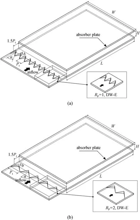
Figure 2 Test section with DW-E for (a) RP=1 and (b) RP=2
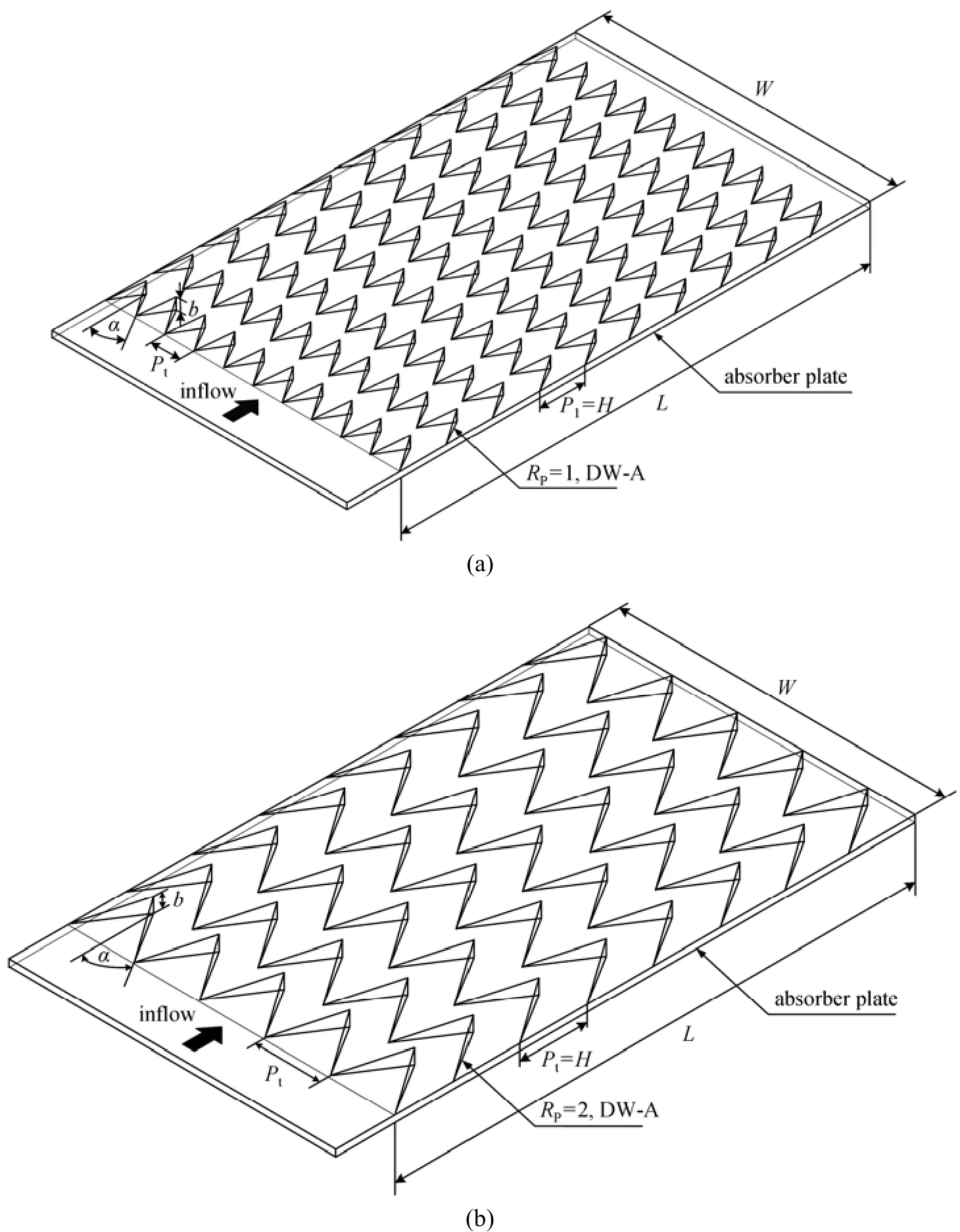
Figure 3 Test section with DW-A for (a) RP=1 and (b) RP=2
Air, as the test fluid in both the heat transfer and pressure drop experiments, was directed into the systems by a 1.45 kW high-pressure blower. The operating speed of the blower was varied by using an inverter to provide desired air flow rates, which was measured by an orifice plate pre-calibrated by using hot wire and vane-type anemometers. The pressure across the orifice was measured using an inclined manometer. In order to measure temperature distributions on the absorber plate, ten thermocouples were fitted to the plate wall. They were attached in holes drilled from the rear face and centered of the wall with the respective junctions positioned within 2 mm of the inside wall and axial separation was 40 mm apart. To measure the inlet and outlet bulk temperatures, two and four thermocouples were positioned upstream and downstream of the test duct entry and exit, respectively. All thermocouples were type K, 1.6 mm diameter wire. The thermocouple voltage outputs were fed into a data acquisition system and then recorded via a laptop computer.
Two static pressure taps were located at the top of the principal channel wall to measure axial pressure drops across the test section including the vortex generator, used to evaluate average friction factor. These were located at the center line of the channel. One of these taps is 30 mm upstream of the leading edge of the channel and the other is 30 mm upstream of the trailing edge. The pressure drop was measured by a digital differential pressure and a data logger connected to the 3 mm diameter taps and recorded via the laptop.
To quantify the uncertainties of measurements the reduced data obtained experimentally were determined. The uncertainty in the data calculation was based on Ref. [29]. The maximum uncertainties of non-dimensional parameters were ±5% for Reynolds number, ±8% for Nusselt number and ±10% for friction factor. The uncertainty in the axial velocity measurementwas estimated to be less than ±5%, and pressure had a corresponding estimated uncertainty of ±5%, whereas the uncertainty in temperature measurement at the channel wall was about ±0.5%.
3 DATA REDUCTION
The goal of this study is to investigate the Nusselt number in the channel. The Reynolds number based on the channel hydraulic diameter, Dh=2HW/(H+W), is given by

where U and ν are the mean air velocity of the channel and kinematics viscosity of air, respectively. The average heat transfer coefficient, h, is evaluated from the measured temperatures and heat input. With heat added uniformly to fluid (Qair) and the temperature difference of wall and fluid (Tw-Tb), the average heat transfer coefficient will be evaluated via
with

and
The term A is the convective heat transfer area of the heated upper channel wall, whereassT˜ is the average surface temperature obtained from local surface temperatures, Ts, along the axial length of the heated channel. m., Cp, V and I are the air mass flow rate, specific heat, voltage and current, respectively. Then, average Nusselt number, Nu, is written as

The friction factor, f, is evaluated by
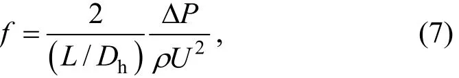
where ΔP is a pressure drop across the test section and ρ is density. All of thermo-physical properties of the air are determined at the overall bulk air temperature, Tb, from Eq. (4).
For equal pumping power,

in which V. is volumetric air flow rate and the relationship between friction and Reynolds number can be expressed as
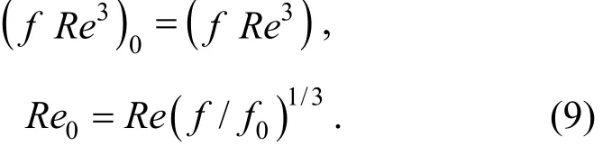
The thermal enhancement factor (η) defined as the ratio of heat transfer coefficient of an augmented surface, h to that of the smooth surface, h0, at the same pumping power:
4 RESULTS AND DISCUSSION
4.1 Verification of smooth channel
The experimental results on heat transfer and friction characteristics in a smooth wall channel are first validated in terms of Nusselt number (Nu) and friction factor (f). Both Nu and f obtained from the present experiment are, respectively, compared with the Dittus-Boelter and Blasius correlations in the open literature [30] for turbulent flow in ducts.
Dittus-Boelter correlation

Blasius correlation

Figures 4 (a) and 4 (b) show respectively, the comparison of measured Nu and f with Eqs. (11) and (12). In the figure, the present results agree very well within ±6% for Nu and f correlations.
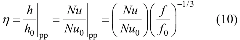
Figure 5 Variation of (a) Nu and (b) Nu/Nu0with Re▲ α=60°, RP=1; ● α=45°, RP=1; ■ α=30°, RP=1; △ α=60°, RP=2; ○ α=45°, RP=2; □ α=30°, RP=2;smooth channel
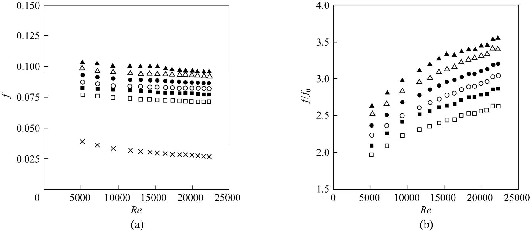
Figure 6 Variation of (a) f and (b) f/f0with Re▲ α=60°, RP=1; ● α=45°, RP=1; ■ α=30°, RP=1; △ α=60°, RP=2; ○ α=45°, RP=2; □ α=30°, RP=2;smooth channel
4.2 Effect of attack angle
In a uniform heat-flux absorber plate fitted with DW-Es at RP=1 and 2 on the entrance of the test channel, the experimental results on Nu and f under turbulent flow conditions for all DW-E cases is depicted in Fig. 5 (a). It can be observed that the DW-Es provide considerable heat transfer enhancement with a similar trend as of the smooth channel. The Nu increases with the rise of Re, because the DW-Es provide multiple vortex flow pairs and the increase in the turbulence degree of flow. It is worth noting that for the DW-E at RP=1, the 60° angle yields the highest Nu while 45° performs better than 30°. This can be attributed to the higher attack angle creating the stronger vortex flows and thus enhancing faster fluid mixing between the central core and the near wall regions. The increases in Nu from using the DW-Es at RP=1 and 2 are around 155%-159% and 148%-154% above the smooth channel, respectively, depending on Re.
The Nu ratio, Nu/Nu0, defined as a ratio of augmented Nu to Nu of smooth channel plotted against the Re value is depicted in Fig. 5 (b). In the figure, the Nu/Nu0tends to decrease slightly with the rise of Re for all. The Nu/Nu0obtained from the DW-E with α=60°, 45° and 30° are, respectively, around 159%, 157% and 155%; and 154%, 152% and 148% over the smooth channel for RP=1 and 2.
The effect of the DW-Es on the isothermal pressure drop across the tested channel is presented in Fig. 6 (a) in terms of f versus Re. In the figure, it is apparent that the DW-Es give rise to a considerable increase in f above the smooth channel due to the increased face area, the reverse flow, and higher form drag. As expected, f of the DW-E with RP=1 is considerably higher than that with RP=2.
The variation of isothermal friction factor ratio, f/f0, with Re for the DW-Es is shown in Fig. 6 (b), showing that the f/f0is increased with the increment of Re and α values. The increase in f/f0for the DW-Es ismuch larger than the smooth channel, especially at α=60°. The average increases in the f/f0for the DW-Es with α=60°, 45° and 30° are, respectively, about 3.25, 2.92 and 2.61; and 3.1, 2.75 and 2.41 times for RP=1 and 2. This implies that the presence of the DW-Es with the lower attack angle (α=30°) leads to a nearly similar increase rate in Nu and f values. Therefore, in the next section, only the DW-As with α=30° will perform by placing on the absorber plate.
4.3 Effect of DWs placed on absorber plate (DW-As)
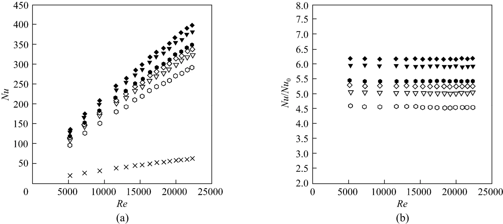
Figure 7 Variation of (a) Nu and (b) Nu/Nu0with Re for various DW-A heights◆ b/H=0.5, RP=1; ▼ b/H=0.4, RP=1; ■ b/H=0.3, RP=1; ◇ b/H=0.5, RP=2; ▽ b/H=0.4, RP=2; b/H=0.3, RP=2;smooth channel
Figures 7 (a) and 7 (b), respectively, presents the Nu and Nu/Nu0in the solar air heater channel mounted periodically with multiple 30° DW-A pairs at three different relative heights, b/H=0.5, 0.4 and 0.3. It is visible in Fig. 7 (a) that the Nu for the DW-As increases with the rise of Re and of larger b/H values. The solar air heater channel fitted with the DW-As provides higher heat transfer rate than that with the DW-E. The heat transfer rates for the DW-As at b/H=0.5, 0.4 and 0.3, are, respectively, around 617%, 594% and 543%; and 526%, 504% and 455% above that for the smooth channel with RP=1 and 2. The use of DW-As results in nearly constant Nu/Nu0values independent of Re. A close examination reveals that the 30° DW-A yields much higher heat transfer than DW-E, indicating that the LVs created by DW-As are stronger than those by DW-Es producing the decaying LVs. For the 30° DW-As at RP=1 and 2, the values of Nu/Nu0are above 6.17-4.55, independent of Re as can be seen in Fig. 7 (b).
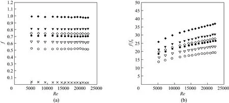
Figure 8 Variation of (a) f and (b) f/f0with Re for various DW-A heights◆ b/H=0.5, RP=1; ▼ b/H=0.4, RP=1; ■ b/H=0.3, RP=1; ◇ b/H=0.5, RP=2; ▽ b/H=0.4, RP=2; b/H=0.3, RP=2;smooth channel
The variation of isothermal friction factor, f and friction factor ratio, f/f0values with Re for DW-As at three b/H and two RPvalues is depicted in Figs. 8 (a) and 8 (b), respectively. In Fig. 8 (a), the f value forlarger b/H DW-As is found to be considerably higher than that for the lower one and tends to be irrelevant of Re. The rise in f for DW-As is much higher than that for DW-E and smooth channel alone, especially for b/H=0.5. The f value for DW-A with RP=1 is found to be considerably higher than that with RP=2. The mean increases in f for DW-As at b/H=0.5, 0.4 and 0.3 are, respectively, about 33.2, 27.4 and 23.9; and 25.07, 20.91 and 17.55 times above the smooth channel for RP=1 and 2. Fig. 8 (b) presents f/f0in the presence of DW-As versus Re and f/f0increases with increasing the Re and b/H values. It is visible that f/f0of b/H=0.3, RP=1 and b/H=0.5, RP=2 shows a nearly similar increase. The average increases in f/f0for DW-A at b/H=0.5 are, respectively, about 13 and 12 times over DW-E for RP=1 and 2.
4.4 Performance evaluation
Figure 9 shows the variation of the thermal enhancement factor (η) with Re for DW-A and DW-E under a similar pumping power. In the figure, η tends to decrease with the increment of Re. For DW-E, RP=1 gives the highest η. The mean η for the DW-E with α=30°, 45° and 60° are around 1.12, 1.097, and 1.077; and 1.109, 1.083, and 1.064 for RP=1 and 2, respectively. The η of DW-E at RP=1 is higher than that of the one at RP=2 for all Re values. For DW-E, the attack angles, α=60° and 45°, cause high pressure drop, f and f/f0, but α=30° provides the highest η because of the reduction of pressure loss considerably. DW-E with α=30° and RP=1 shows the best η of about 1.22 at lower Re.
For the 30° DW-A, it is noted that η is found to be much higher than DW-E while RP=1 performs better than RP=2. The 30° DW-A with RP=1 and b/H=0.4 gives the highest η at lower Re. The maximum η values for 30° DW-A with RP=1 at b/H=0.5, 0.4 and 0.3, are, respectively, about 2.09, 2.15 and 2.05. At lower Re, the 30° DW-A at b/H=0.5 yield the η about 42% and 39% higher than DW-E at RP=1 and 2, respectively.

Figure 10 Predicted data of (a) Nu and (b) f versus experimental data△ RP=1; ○ RP=2
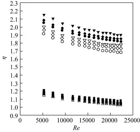
Figure 9 Variation of η with Re▲ α=60°, RP=1; ● α=45°, RP=1; ■ α=30°, RP=1;△ α=60°, RP=2; ○ α=45°, RP=2; □ α=30°, RP=2;◆ b/H=0.5, RP=1; ▼ b/H=0.4, RP=1; ■ b/H=0.3, RP=1;◇ b/H=0.5, RP=2; ▽ b/H=0.4, RP=2; b/H=0.3, RP=2
The Nu, and f values for DW-Es correlated with Re, Prandtl number (Pr) and α, as formulated in Eqs. (13)-(16), are plotted against measured data in Figs. 10 (a) and 10 (b), respectively. Majority of the measured data falls within ±4% and ±5% for the predicted Nu, and f, respectively.
Correlations for Nu and f of using DW-Es at b/H=0.5; RP=1 and 2; α=30°, 45° and 60°; Re=5000 to 24000 are developed as follows:
Correlation for DW-E with RP=1

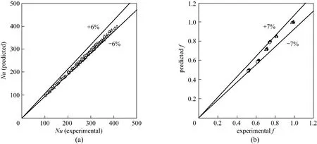
Figure 11 Predicted data of (a) Nu and (b) f versus experimental data△ RP=1; ○ RP=2
Correlation for DW-E with RP=2

For the 30° DW-As, Nu and f are correlated as functions of Re, Pr and b/H as Eqs. (17)-(20) and plotted against measured data as depicted in Figs. 11 (a) and 11 (b), respectively. Majority of the measured data falls within ±6% and ±7% for the predicted Nu and f, respectively.
Correlations for the 30° DW-As at RP=1 and 2, b/H=0.3, 0.4 and 0.5 for Re=5000 to 24000 are as follows.
Correlation for 30° DW-A at RP=1

Correlation for 30° DW-A at RP=2

5 CONCLUSIONS
An experimental study has been carried out to investigate flow friction and heat transfer characteristics in a high aspect ratio channel (AR=10) with DW-Es mounted at the tested-section entrance and with multiple 30° DW-As mounted repeatedly on the absorber plate of the tested channel at different attack angles for Re of 5000-24000. The summary is as follows.
(1) The presence of DW-Es at α=60° causes a high pressure drop, f/f0=2.1-3.5 but also provides considerable heat transfer augmentation, Nu/Nu0= 1.5-1.61.
(2) Nu from DW-E shows a trend of increase with the rise in α and Re.
(3) The 30° DW-As provide higher heat transfer rate, friction factor and thermal enhancement factor than DW-Es.
(4) The 30° DW-Es at RP=1 yield the highest η of about 1.22 while the 30° DW-As with b/H=0.4 yield the best η of about 2.15 at lower Re.
NOMENCLATURE
A convection heat transfer area of channel, m2ARaspect ratio of channel (=W/H)
b winglet height, m
Cpspecific heat capacity of air, J·kg−1·K−1
Dhhydraulic diameter of channel, m
e rib height, m
f friction factor
H channel height, m
h average heat transfer coefficient, W·m−2·K−1
I current, A
k thermal conductivity of air, W·m−1·K−1
L length of test channel, m
m. mass flow rate of air, kg·s−1
Nu Nusselt number (=hD/k)
Pllongitudinal pitch spacing, m
Pttransverse pitch spacing, m
Pr Prandtl number (=Cp·μ/k)
ΔP pressure drop, Pa
Q heat transfer, W
RLlongitudinal pitch ratio (Pl/H)
RPtransverse pitch ratio (Pt/H)
Re Reynolds number (=UD/ν)
T temperature, K
t thickness of DW, m
U mean velocity, m·s−1
V voltage, V
V. volumetric flow rate, m3·s−1
W width of channel, m
α attack angle of fin, (°)
η thermal enhancement factor
μ viscosity of air, kg·m−1·s−1
ν kinematics viscosity, m2·s−1
ρ density of air, kg·m−3
Subscripts
b bulk
conv convection
i inlet
o out
pp pumping power
s channel surface
0 smooth channel
REFERENCES
1 Promvonge, P., “Thermal augmentation in circular tube with twisted tape and wire coil turbulators”, Energy Convers. Manag., 49, 2949-2955 (2008).
2 Promvonge, P., “Thermal performance in circular tube fitted with coiled square wires”, Energy Convers. Manag., 49 (5), 980-987 (2008).
3 Thianpong, C., Chompookham, T., Skullong, S., Promvonge, P.,“Thermal characterization of turbulent flow in a channel with isosceles triangular ribs”, Int. Commun. Heat Mass Transfer, 36, 712-717 (2009).
4 Sripattanapipat, S., Promvonge, P., “Numerical analysis of laminar heat transfer in a channel with diamond-shaped baffles”, Int. Commun. Heat Mass Transfer, 36 (1), 32-38 (2009).
5 Promvonge, P., Chompookham, T., Kwankaomeng, S., Thianpong, C., “Enhanced heat transfer in a triangular ribbed channel with longitudinal vortex generators”, Energy Convers. Manag., 51 (6), 1242-1249 (2010).
6 Chompookham, T., Thianpong, C., Kwankaomeng, S., Promvonge, P., “Heat transfer augmentation in a wedge-ribbed channel using winglet vortex generators”, Int. Commun. Heat Mass Transfer, 37, 163-169 (2010).
7 Promvonge , P., Khanoknaiyakarn, C., Kwankaomeng, S., Thianpong, C., “Thermal behavior in solar air heater channel fitted with combined rib and delta-winglet”, Int. Commun. Heat Mass Transfer, 38, 749-756 (2011).
8 Sahu, M.M., Bhagoria, J.L., “Augmentation of heat transfer coefficient by using 90° broken transverse ribs on absorber plate of solar air heater”, Renew. Energy, 30 (13), 2057-2063 (2005).
9 Mittal, M.K., Varun, Saini, R.P., Singal, S.K., “Effective efficiency of solar air heaters having different types of roughness elements on absorber plate”, Energy, 32, 739-745 (2007).
10 Aharwal, K.R., Gandhi, B.K., Saini, J.S., “Experimental investigation on heattransfer enhancement due to a gap in an inclined continuous rib arrangement in a rectangular duct of solar air heater”, Renew. Energy, 33, 585-596 (2008).
11 Varun, Saini, R.P., Singal, S.K., “Investigation of thermal performance of solar air heater having roughness elements as a combination of inclined and transverse ribs on the absorber plate”, Renew. Energy, 33 (6), 1398-1405 (2008).
12 Momin, A.M.E., Saini, J.S., Solanki, S.C., “Heat transfer and friction in solar air heater duct with V-shaped rib roughness on absorber plate”, Int. J. Heat Mass Transfer, 45, 3383-3396 (2002).
13 Chandra, P.R., Alexander, C.R., Han, J.C., “Heat transfer and friction behaviour in rectangular channels with varying number of ribbed walls”, Int. J. Heat Mass Transfer, 46, 481-495 (2003).
14 Tanda, G., “Heat transfer in rectangular channels with transverse and V-shaped broken ribs”, Int. J. Heat Mass Transfer, 47, 229-243 (2004). 15 Chang, S.W., Liou, T.M., Lu, M.H., “Heat transfer of rectangular narrow channel with two opposite scale roughened walls”, Int. J. Heat Mass Transfer, 48, 3921-3931 (2005).
16 Katoh, K., Choi, K., Azuma, T., “Heat transfer enhancement and pressure loss by surface roughness in turbulent channel flows”, Int. J. Heat Mass Transfer, 43, 4009-4017 (2000).
17 Varun, Saini, R.P., Singal, S.K., “A review on roughness geometry used in solar air heaters”, Solar Energy, 81, 1340-1350 (2007).
18 Murugesan, P., Mayilsamy, K., Suresh, S., “Turbulent heat transfer and pressure drop in tube fitted with square-cut twisted tape”, Chin. J. Chem. Eng., 18, 609-617 (2010).
19 Murugesan, P., Mayilsamy, K., Suresh, S., “Heat transfer and friction factor studies in a circular tube fitted with twisted tape consisting of wire-nails”, Chin. J. Chem. Eng., 18, 1038-1042 (2010).
20 Gunes, S., Ozceyhan, V., Buyukalaca, O., “Heat transfer enhancement in a tube with equilateral triangle cross sectioned coiled wire inserts”, Eχp. Therm. Fluid Sci., 34 (6), 684-691 (2010).
21 Promvonge, P., Skullong, S., Kwankaomeng, S., Thiangpong, C.,“Heat transfer in square duct fitted diagonally with angle-finned tape—Part 1: Experimental study”, Int. Commun. Heat Mass Transfer, 39 (5), 617-624 (2012).
22 Promvonge, P., Skullong, S., Kwankaomeng, S., Thiangpong, C.,“Heat transfer in square duct fitted diagonally with angle-finned tape—Part 2: Numerical study”, Int. Commun. Heat Mass Transfer, 39 (5), 625-633 (2012).
23 Eiamsa-ard, S., Koolnapadol, N., Promvonge, P., “Heat transfer behavior in a square duct with tandem wire coil element insert”, Chin. J. Chem. Eng., 20 (5), 863-869 (2012).
24 Gentry, M.C., Jacobi, A.M. “Heat transfer enhancement by delta-wing vortex generators on a flat plate: Vortex interactions with the boundary layer”, Eχp. Therm. Fluid Sci., 14 (3), 231-242 (1997).
25 Kwak, K.M., Torii, K., Nishino, K., “Simultaneous heat transfer enhancement and pressure loss reduction for finned-tube bundles with the first or two transverse rows of built-in winglets”, Eχp. Therm. Fluid Sci., 29 (5), 625-632 (2005).
26 Jacobi, A.M., Shah, R.K., “Heat transfer surface enhancement through the use of longitudinal vortices: A review of recent progress”, Eχp. Therm. Fluid Sci., 11 (3), 295-309 (1995).
27 Fiebig, M., “Embedded vortices in internal flow: Heat transfer and pressure loss enhancement”, Int. J. Heat Fluid Flow, 16 (5), 376-388 (1995).
28 Tian, L.T., He, Y.L., Lei, Y.G., Tao, W.Q., “Numerical study of fluid flow and heat transfer in a flat-plate channel with longitudinal vortex generators by applying field synergy principle analysis”, Int. Commun. Heat Mass Transfer, 36 (2), 111-120 (2009).
29 ANSI/ASME, “Measurement uncertainty”, PTC 19. 1-1985, Part I, USA (1986).
30 Incropera, F., Dewitt, P.D., Fundamentals of Heat and Mass Transfer, 6th edition, John Wiley & Sons, USA (2007).
10.1016/S1004-9541(14)60030-6
2013-03-03, accepted 2013-09-30.
* Supported by the Thailand Research Fund (TRF).
** To whom correspondence should be addressed. E-mail: sfengsps@src.ku.ac.th
杂志排行

Chinese Journal of Chemical Engineering的其它文章
- Influence of Design Margin on Operation Optimization and Control Performance of Chemical Processes*
- Measurement and Modeling for the Solubility of Hydrogen Sulfide in Primene JM-T*
- Enhancing Structural Stability and Pervaporation Performance of Composite Membranes by Coating Gelatin onto Hydrophilically Modified Support Layer*
- Photocatalytical Inactivation of Enterococcus faecalis from Water Using Functional Materials Based on Natural Zeolite and Titanium Dioxide*
- A Group Contribution Method for the Correlation of Static Dielectric Constant of Ionic Liquids*
- Interaction Analysis and Decomposition Principle for Control Structure Design of Large-scale Systems*