Effect of bank slope on the flow patterns in river intakes*
2014-06-01SEYEDIANSeyedMorteza
SEYEDIAN Seyed Morteza
Department of Hydraulic Structure, Ghonbad Kavoos University, Ghonbad Kavoos, Iran, E-mail: s.m.seyedian@gmail.com
BAJESTAN Mahmood Shafai
Department of Hydraulic Structure, Shahid Chamran University, Ahvaz, Iran
FARASATI Masoomeh
Department of Water Engineering, Razi University, Kermanshah, Iran
Effect of bank slope on the flow patterns in river intakes*
SEYEDIAN Seyed Morteza
Department of Hydraulic Structure, Ghonbad Kavoos University, Ghonbad Kavoos, Iran, E-mail: s.m.seyedian@gmail.com
BAJESTAN Mahmood Shafai
Department of Hydraulic Structure, Shahid Chamran University, Ahvaz, Iran
FARASATI Masoomeh
Department of Water Engineering, Razi University, Kermanshah, Iran
(Received January 29, 2013, Revised May 27, 2013)
In this work, we studied the dimensions of stream tube in the vertical as well as inclined bank conditions. Data were collected from both a physical model and a 3-D numerical model (SSIIM 2). Equations for predicting stream tube dimensions were presented and compared with existing formulae. In comparison with vertical bank, it is found that inclining bank causes the bottom stream tube width to be greater than at the surface. The strength of secondary current formed at the entrance of branch channel is reduced. These changes in flow pattern can reduce the amount of sediment delivery into the intake.
lateral intakes, flow pattern, bank slope, stream tube, SSIIM 2 model
Introduction
Investigations on flow pattern at hydraulic structures has been the goal of many experimental researches[1-5]. Descriptions of flow patterns in braided river can be found in Ref.[6], in curved river in Ref.[7] and at river confluence in Ref.[8]. Knowing the structure or flow pattern in river intake is essential for hydraulic engineers because the amount of flow discharge and sediments rate into the branch channel are highly dependent on the features of this pattern. Modification of the flow conditions not only can reduce the amount of sediments entering the intake, but also would help engineers to choose suitable measures of controlling sediments. The characteristics of dividing flows was examined experimentally[9-11]and numerically[12-14]. The width of stream tube (stream tube is area between the left wall and dividing stream-surface, see subsection 1.2) in the main channel determines how much flow discharge enters the lateral channel[15]. Based on the previous studies conducted on lateral in-
takes from a rectangular channel, the stream tube width on surface is smaller than that on bed or it has a trapezoidal shape cross section with greater width at the bottom. So, due to the fact that the sediment concentration on bed is greater than that on surface, the entering sediment would be more than the average sediment of the channel. This implies that any modification in stream tube cross section in such a way that the bottom width reduces or surface width increases can cause to reduce the sediment delivery into the intake. For an off-take from a rectangular canal respectively for the smooth bed, and for the rough bed were given as[15]:

whereW1stands for the main channel width, andBsandBbare the stream tube widths on surface and bed, respectively (see Fig.1). It was concluded that there would be a direct relationship between secondary flow strength and the ratio of flow velocity in the intake tothat in the main channel. Also the corresponding expressions for determining the stream tube width for an off-take from a rectangular channel were presented[17]:
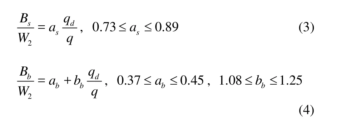
whereqdandqare flow discharges per unit width in the lateral and main channels, respectively, andW2is the width of the lateral channel. Equation (5) for designing submerged vanes aimed to control sediment entry was offered in Ref.[18]

whereQdandQstand for discharges in the lateral channel and in the main channel, respectively, and the ratioQd/Q(orQr) is the diversion flow ratio. The following equation for calculating the stream tube width in middle depth (B50%) was presented[19]

Two booms was designed to prevent entering suspended particles in water into the intake[20]. The flow enters the intake smoother and the net width of the intake increases for the passage of flow when the diversion angle decreases. Also with decreasing diversion angle, the stream tube width on bed decreases[21]. The hydraulic conditions ofo90 intake by employing the Fluent model was simulated and showed that the RSM turbulence model was better than thek-εmodel, and the latter was better than thek-εmodel. The stream width on the bed is greater than that on the surface, and the dimension of separation zone grows from bed towards surface[22].
Entering sediment is always influenced by the roughness ratio (ks/y0), whereksis the roughness of the main channel bed, andy0is the depth of water in the main channel. Accordingly, while the bed roughness increases, sediments delivery decreases as secondary currents strength fails[17]. The secondary strength increases with increasing diversion flow ratio, and its strength decreases in the direction towards downstream[23]. The presence of sill in the intake in the direct path of river leads to a decline in secondary flow width at the entrance[24].
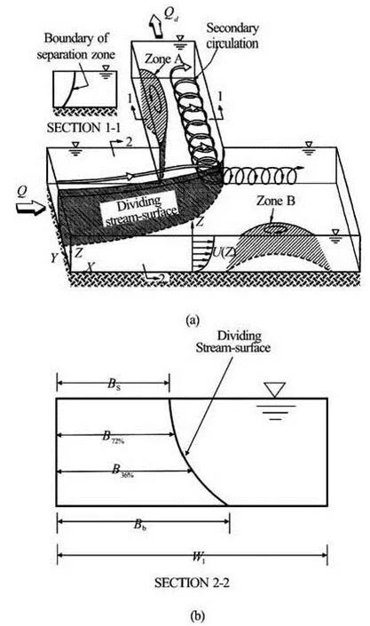
Fig.1 3-D Flow pattern in lateral intake[16]
In comparison with excessive researches on flow patterns in intakes, less work has been carried out on inclined bank channel. In this research, first the 3-D velocity components were measured in a physical model. In this model ao90 off-take channel was installed at the side of a main channel with four different bank slopes. Then using these data the 3-D model SSIIM 2 was calibrated and verified. By running the model for different hydraulic conditions more data were collected. Finally the results of both experimental and numerical model were used to develop statements for predicting stream tube dimensions and the strength of secondary circulation inside the off-take channel.
1. Materials and methods
1.1Laboratory model
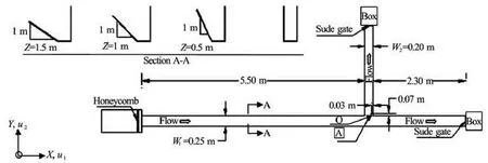
Fig.2 Plan view of experimental layout
Laboratory equipments consisted of a main flume with a length of 8 m and a width of 0.25 m, and a lateral channel of 2.25 m by 0.2 m connected to the main channel with ao90 angle. The channel was designed so that there was a possibility for the lateral channel side bank to be inclined. The experiments were carried out in the vertical case as well as in the cases of three slopesz=0.5, 1, and 1.5 (1 in the vertical direction andzin the horizontal direction). The depth of the main channel and the branch channel was 0.7 m, and at the entrance of the main channel a honeycomb was installed. At the ends of the main as well as the branch channels a sluice gate was set to regulate the water surface for each channel. The circulation system of water was a closed circuit, and water was provided from an underground reservoir. At the ends of the main and the lateral channels, the currents entered a honeycomb and the discharges were measured by the 56oand 90oweirs. Figure 2 shows the locations of lab apparatus. The measurements were conducted in a 0.25 m depth and a three-component Nortek acoustic Doppler velocimeter (ADV) was used to measure the velocities.
The velocity components were measured at three levels: near the bed (about 0.01 m), 0.09 m and 0.18 m from the flow depth, the measurements at each point of the network were accomplished with a frequency of 50 Hz in 45 s. For each main channel bank slope, tests were carried out for the flow depths 0.25 m and at five different Froude numbers ranging from 0.25 to 0.45. For each test, the flow was allowed to enter the flume to reach the desired flow depth and discharge while the gates at the downstream of both main and lateral channels were fully opened (free flow condition). Then the velocity was measured at the depth of 0.25 m. The variation range of the variables in the present study is given in Table 1.
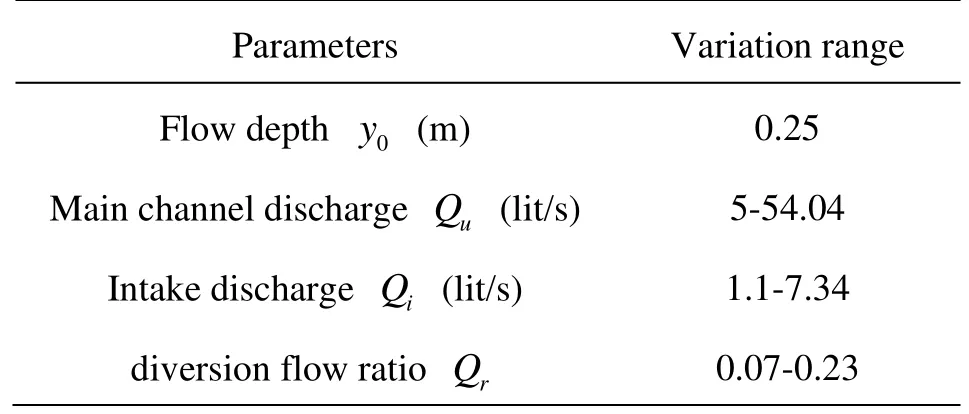
Table 1 Variation ranges of parameters
1.2SSIIM 2
The 3-D model SSIIM 2 was used to obtain some desirable data. With the SSIIM program the 3-D Navier-Stokes equations in a general non-orthogonal coordinate system was solved. These equations were discretized with a control volume approach. The SIMPLE method was also used for the pressure coupling. Additionally the SIMPLEC method was invoked. An implicit solver was used, producing the velocity field in geometry. The velocities were used when solving the convection-diffusion equations for different sediment sizes. The three-dimensional model was constructed by the equations below. The Navier-Stokes equations for non-compressible and constant density flow can be modeled as

whereUis the Reynolds-averaged velocity over timet,Xthe spatial coordinate,ρthe water density,pthe Reynolds-averaged pressure, andδthe Kronecker delta[26].
The second term on the right side of the equation is the Reynolds stress term. In order to evaluate this term, a turbulence model is required. The SSIIM program can use different turbulence models determined by its user, but the default turbulence model is thek-εmodel. The velocity gradient towards the wall is often very steep, thus it is assumed that the velocity profile follows a certain empirical function called a wall law. The default wall law in SSIIM is

whereU*is the shear velocity,κis the Karman constant equal to 0.4,yis the water depth andksis the roughness equivalent to a diameter of particles on the bed[25,26].
In this study, we applied a constant volume flow rate as inflow boundary in SSIIM 2. The outflow water depth was chosen manually. To determine the eddy-viscosity in the entrance section a simple turbulence model was used. For all parameters at outer boundaries the zero gradient conditions were implemented.
A manually chosen time step is required. To avoid instabilities in the computation, different time steps for difeferent runs were chosen.
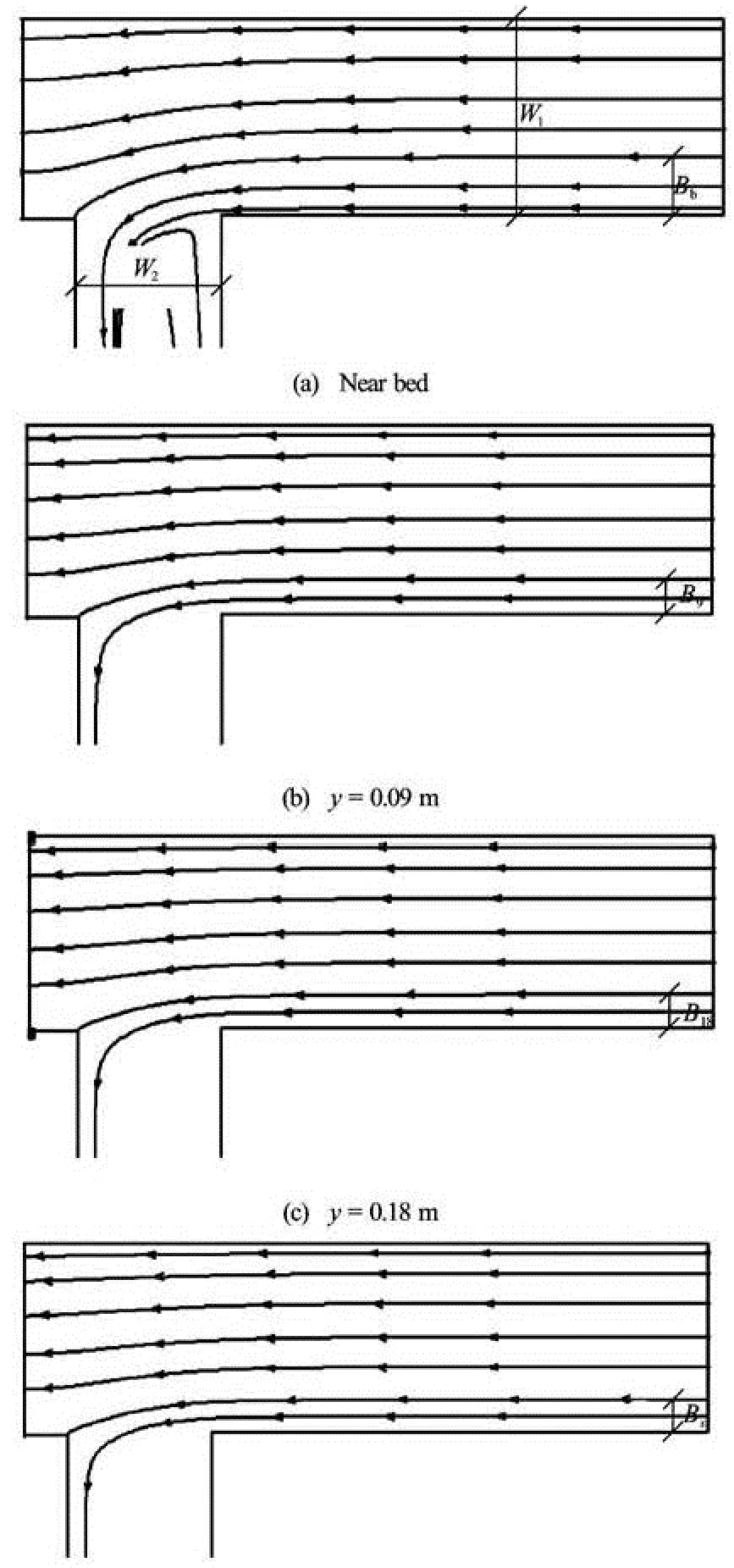
Fig.3 Dividing stream surface
Due to the 3-D complicated flows in the intakes, the model must be first calibrated for the conditions compatible with laboratory ones. In the present study, following our goals, we used the stream tube dimensions for calibrations in such a way that with changing some parameters like discretization scheme, relaxation factor, time step, utilized turbulence model, etc., we could obtain the stream tube widths from the numerical model and compare them with the lab results. Conformity among the values in mathematical and laboratory models indicates a proper overlap of velocity profiles in the directions of the main channel (U1) and the lateral channel (U2). Grid generation of the investigated zone is extremely important, because it can influence the convergence speed as well as the precision of the results.
Figure 3 depicts an example of streamlines resulted from SSIIM 2, drawn respectively for bed and depths of 0.09 m, 0.18 m, and 0.25 m, represented byBb,B9,B18andBswith the Froud number of 0.25 and the diversion flow ratio of 0.16 for the depth of 0.25 m. The stream tube widths on the bed and at depths of 0.09 m and 0.18 m were used in laboratory comparisons.
From among 60 stream tube widths (1 depth, 4 bank slops, 5 Froude numbers and 3 levels of depth) obtained from the physical model, 45 were randomly selected for calibration, and 15 were selected for the verification of SSIIM 2. The above-cited parameters in the model were changed so that to minimize the differences among the 45 stream tube widths in the mathematical and laboratory models. In the verification stage, we compared the difference rates among the remaining 15 widths and the mathematical model. The results approved the capability of model SSIIM 2 in the simulation of hydraulic conditions. Then, the calibration of the dimensions of grids were chosen in the intake and in the main channel, respectively as 0.0125 m 0.0125 m and 0.025 m 0.0125 m in the vertical direction at the 10%, 20%, …, and 90% of the depth. The RNGk-εturbulence model was applied and the one-second time step was applied for execution of the model. Computation was continued until reaching an enough reduction of error.

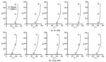
Fig.4 Comparison ofbetween physical and SSIIM2 model
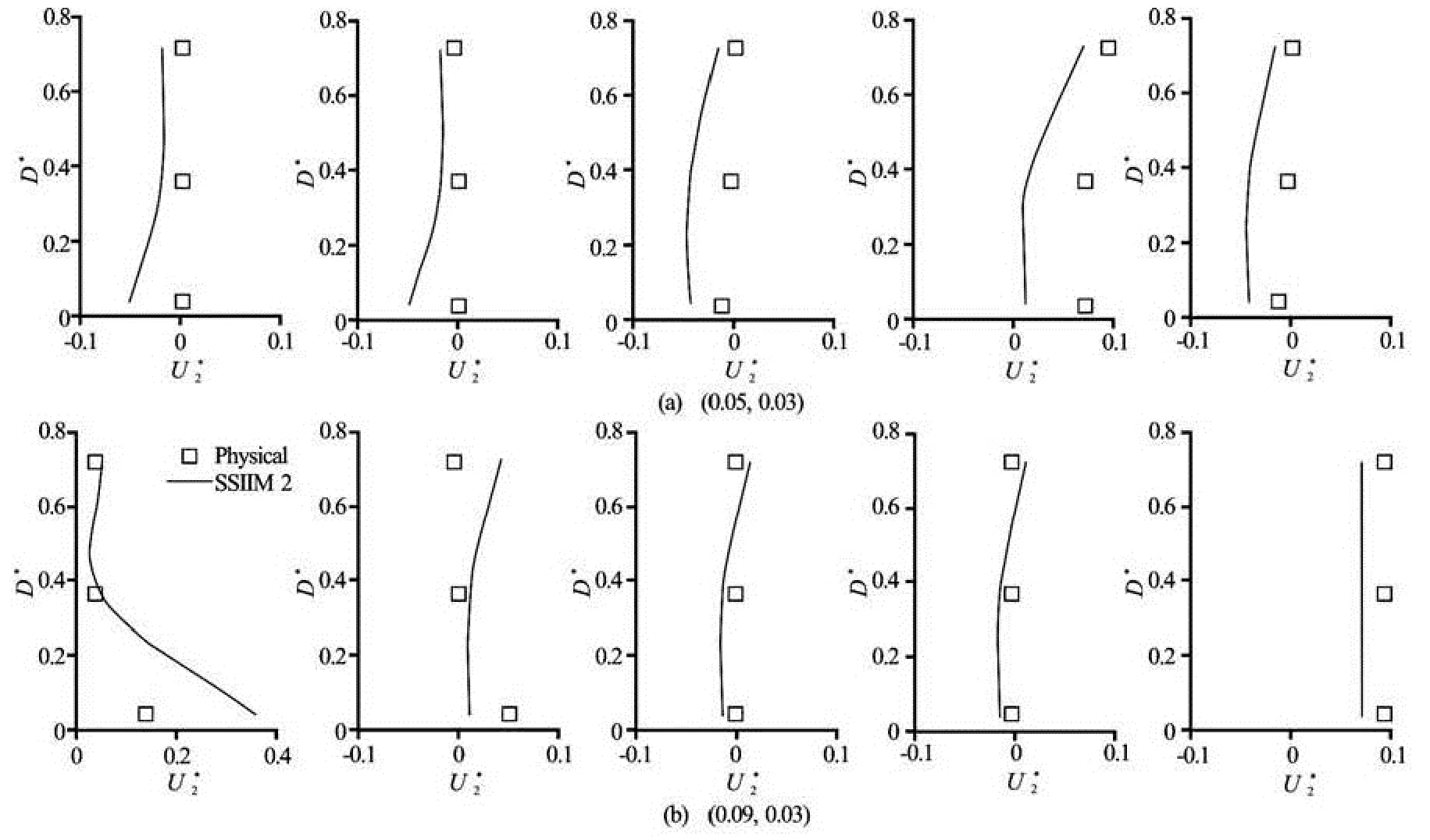
Fig.5 Comparison ofbetween physical and SSIIM2 model
By resorting the calibrated coefficients and parameters, the model was executed for two depths of 0.1 m and 0.2 m at four bank slopes ofz=0, 0.5, 1, and 1.5. Afterwards, the stream tube widths in surface, at 72% of depth (B72%), at 36% of depth (B36%), and on bed were evaluated. In this experiment there was a depth of 0.25 m, however due to the restrictions imposed on the velocimeter and impossibility of measurement on surface, the mathematical model was emplo-yed to determine the stream tube width on surface.
2. Result and discution
2.1Discharge ratio
Figure 6 is a plot of flow discharge ratio versus the upstream flow discharge for four different bank slopes in the tests. According to Fig.6, there is a linear relationship between discharge ratio and upstream flow discharge. These lines have a negative slope which shows when the upstream flow discharge increases and less flow discharge enters the intake. These lines are intersected at upstream flow discharge of about 12 lit/s. In the case of low discharges or low flow depth, the effect of bank slope is not significant and therefore the discharge ratio does not depend on the bank slope. For higher upstream flow discharge, the flow depth at the main channel increases and the effect of bank slope becomes significant. As is observed, when the upstream flow discharge increases, the flow discharge ratio decreases. This is because the flow velocity and consequently the momentum at the flow direction increases, which leads to less diverted flow discharge.
Using regression analysis program for deriving regression model yields

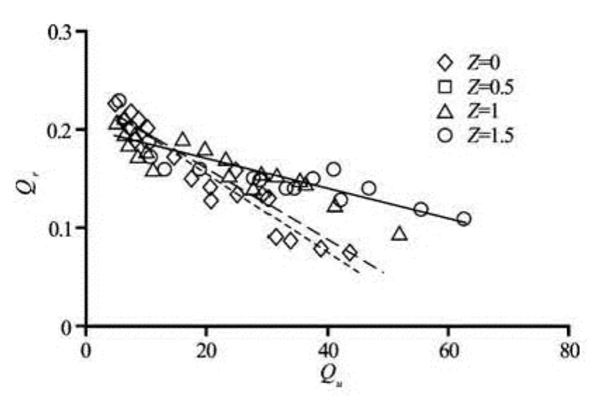
Fig.6 Effect of bank inclination on diversion flow ratio
2.2Stream tube
Figure 7 shows the relation of the dimensionless stream tube width near bed, at 36% and 72% of depth, and near the water surface with diversion flow ratios for four different bank slopes ofz=0, 0.5, 1, and 1.5. In Fig.7(a) the stream tube width is made dimensionless with the lateral channel width, and in other figures with the water surface width. In all the figures, there is a linear relationship between diversion flow ratio and the dimensionless width of stream tube at different levels, and in all graphs the latter increases along with the growth of diversion flow ratio. Except for Fig.7(d) in which there is no specified procedure for changes of the dimensionless stream tube width on surface due to bank inclination, in the other ones with the same diversion flow ratio the value of this parameter decreases. In Figs.7(a), 7(b), and 7(c), the largest increase of the dimensionless stream tube width corresponds to the change of bank position from vertical condition toz=0.5 condition, thereafter by more inclination of the bank the variation procedure runs slowly so that there is no difference between the graphs ofz=1, 1.5.
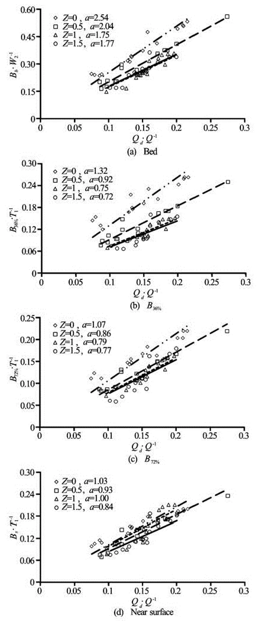
Fig.7 Variation of stream tube width withQr
As was stated above, the dimensionless streamtube width on the surface has no defined relationship with changes in the bank slope (Fig.7(d)), however the line slopes in all cases are smaller than that in the vertical case. The slope of fitted line atz=0.5 is smaller than that of the vertical bank, and it gets close to vertical bank atz=1. The least slope belongs toz= 1.5.
Using regression analysis program for deriving multi-regression models for the cases in Figs.7(a)-7(d) lead respectively to
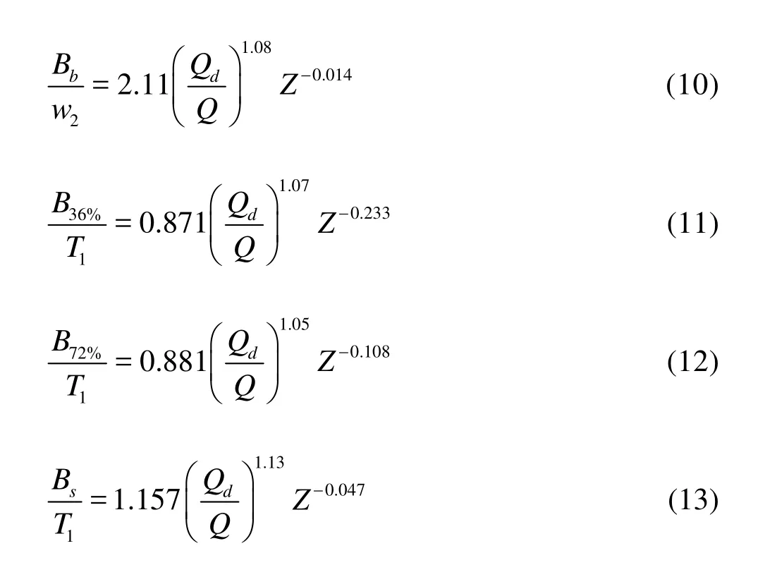
Since for the vertical bank the water surface width equals the channel bed width, in the present research the following equation may be appropriate for the vertical situation Comparing Eqs.(5) and (14) leads to the conclusion that with the same diversion flow ratio the stream tube width on the surface in Eq.(14) would be smaller than that in Eq.(5).

Comparison between the diversion flow ratio relationship with stream tube width in this study with Eq.(5) shows that Eq.(14) is very similar to the Eq.(5).
Figure 8 shows the relations between stream tube width in different vertical layers (Bs,B72%,B36%) made dimensionless with the surface width and stream tube width on the bed at four bank slopes. According to these relations the profile of dividing stream surface (DSS) for each slope is obtained. The coefficients in Fig.8 show that with inclining the bank the stream tube width on the bed decreases relative to 36% of depth, and the profile of (DSS) in the lower layer tends to a line so that inz=1.5 the stream tube widths on the bed is equal to that in 36% of depth. A comparison between Figs.8(a) and 8(b) also reveals the fact that when the stream tube width on the bed is fixed, the inclination of bank causes the increase in stream tube width on the surface and at the 36% of depth. Because in the vertical case the width on the surface is almost half of that on the bed, the increase in surface width leads to the equality of widths on the bed and surface.
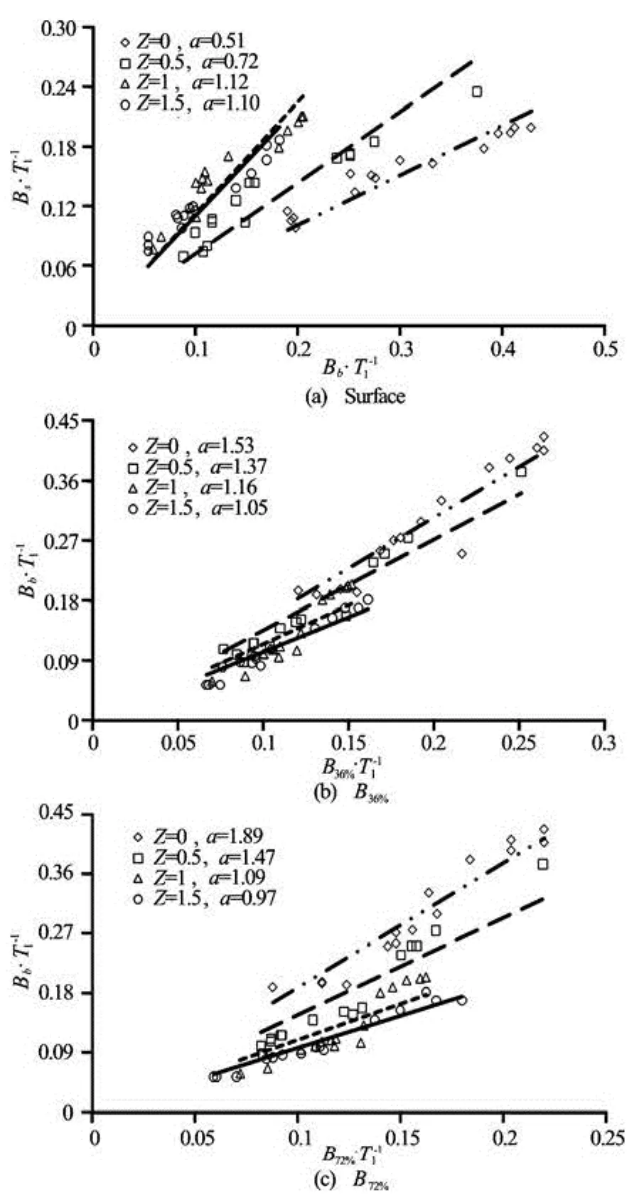
Fig.8 Variation of stream tube width in bed withQr
From Fig.8(c) it is found that in 90oangle the stream tube width at 72% of depth is almost half of that on the bed. With more inclination of the bank the width on the bed nearly equals that in the 72% of depth. Figures 8(a)-8(c) demonstrate that in the 36% and 72% of depth as well as on the surface the stream tube width increases relative to bed while the bank inclines. Atz=0, the profile of DSS in the lower layer is fully curved, by slanting the bank, however, the stream tube width on the upper surfaces increases and the curve is transformed into a line so that atz=1.5 the stream tube width would be the same at all levels (see Fig.9(a)).
Using regression analysis program for derivingmulti-regression models for Figs.8(a)-8(c) leads respectively to
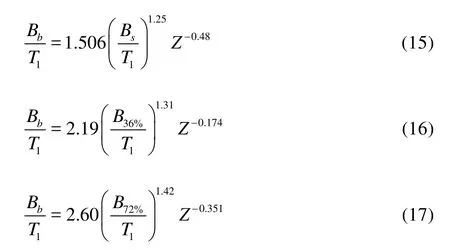
A comparison between the coefficient of stream tube widths on the bed and surface and and between Eqs.(1) and (2) shows that the coefficient has the value between the coefficients offered for smooth and rough beds.

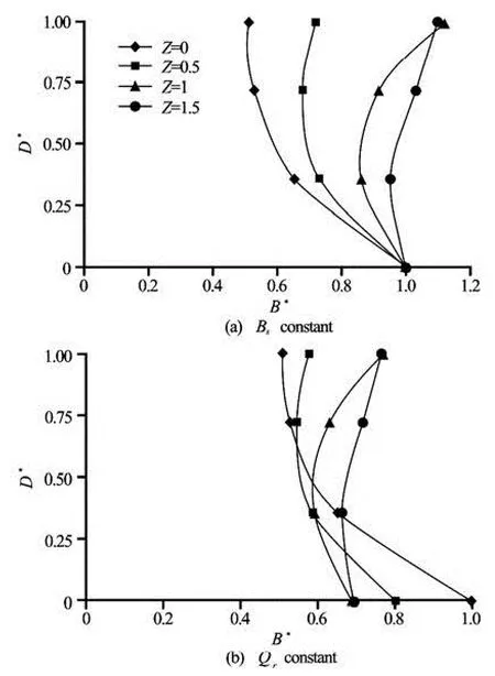
Fig.9 Dimension of stream tube
2.3Profile of dividing stream surface
In the previous subsection it was verified that with inclination of the bank the curvature of DSS declines and approaches linearity. When the stream tube width on the bed is fixed, the profile of the DSS might become what is shown in Fig.9(a). In Fig.9,B*=stream tube width /BbandD*=depth/y0. As was ob-served slanting the bank makes the profile of DSS directs to right and tends to linearity. For the vertical bank the stream tube width in the bed layers is greater than in the surface layer, and the entering discharge to the intake is provided more from lower layers, while when the bank inclines the discharge enters in almost equal shares from all depths into the intake.
As was mentioned above, the changes in stream tube width were compared under the assumption that the tube width on the bed remains constant for all bank slopes. However, from the explanations about these changes it is inferred that for the same diversion flow ratios, the inclination of the bank leads to a decrease in bed width. Figure 9(b) shows an approximate profile of the DSS with a constant diversion flow ratio. It is worth noting that the changes in depth fairly deform these profiles. When the channel contains sediments, the profile shapes of DSS at different bank slopes are of much importance when used to predict the sediment delivery to the lateral channel. The DSS profile of vertical bank is similar to Neari’s results. As is clear, the stream tube width in lower layers where sediment concentration is high is more related to surface layers. In these conditions the delivery is greater than the average rate of sediments in the main channels. As soon as the bank slants (z=0.5), the stream tube width in bed relative to the sloped bank reduces remarkably, and increases a little on the surface. Due to the decrease in stream tube width in the lower layer it is expected that the entering sediment to the intake decreases noticeably. Regarding low concentration in surface layers, one could see no remarkable effect of increased tube width on the sediments rate. Further inclining the bank (z=1) yields a decrease of tube width at the lower 1/3 of depth, and an increase at the upper 2/3. In these situations, the profile of sediment concentration determines delivery rate of sediments. If concentration in the bed layer is higher than that in the upper layers (often is the case), the sediment delivery inz=1 is presumed to decrease with respect toz= 0.5, otherwise it may increase. Atz=1.5 the stream tube width is greater than that atz=1 at all depths. Selecting the optimum slope requires knowledge of the sediment concentration profile, however it seems that in usual conditions the entering sediments to the intake reduces atz=1 with respect to other slopes.
2.4Secondary Circulation
As is illustrated in Fig.1, owing to the imbalance between the transverse pressures at the corner of intake channel downstream bank, a secondary flow occurs. To investigate this secondary flow, its strength inside the intake was examined. Figure 10 shows the secondary current at the three depths of 0.1 m, 0.2 m,and 0.25 m corresponding respectively to diversion ratios of 0.22, 0.17, and 0.14. The secondary current forms in the bottom-left division of the figure (close to the downstream intake bank). At the depth of 0.1 m it is more clearly seen thanks to greater diversion flow ratio.
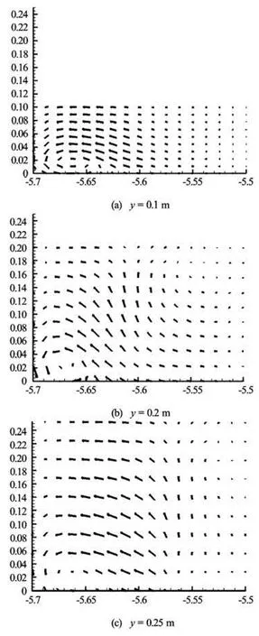
Fig.10 Secondary circulation (the horizontal and vertical axis respectively represent lateral channel width and flow depth)
To determine the secondary circulation strength ()δ, Eq.(19) was used in which the difference in transverse velocity at 36% of depth (U36%) and at bed
(Ub) was found at Point A, 0.03 m from the downstream bank and 0.07 m from the entrance of lateral channel (see Fig.2).

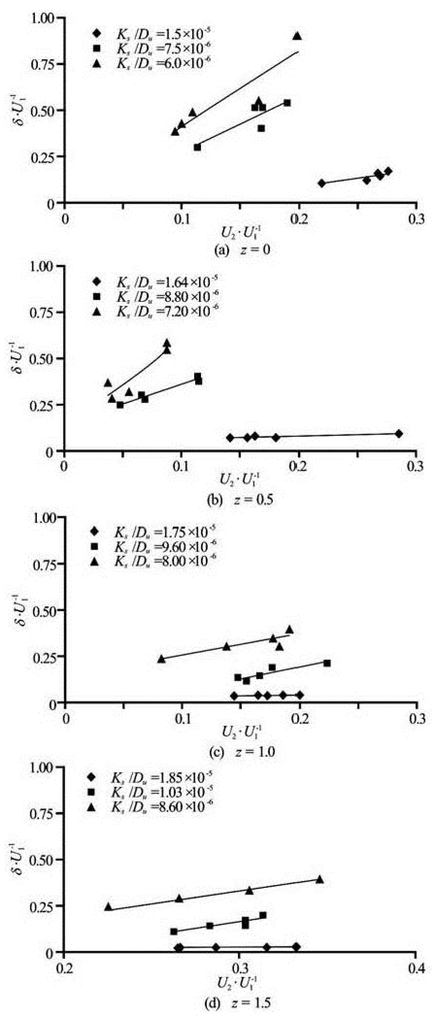
Fig.11 Variation of strength of secondary circulation for different velocity ratios
Figure 11 presents the relationship betweenδand the parameterU2/U1, designating diversion flow ratio and being called “relative velocity”, at four bank slopes (U1andU2are the mean velocities in main and lateral channels, respectively). The graphs for each slope are distinguished based on the roughness ratio. From this figure, it is understood that the strength of secondary circulation increases with the increase in relative velocity, and decreases with the increase in the roughness ratio. Since the roughness ratios for twodepths of 0.2 m and 0.25 m are close to each other, the slopes of fitted lines bear similarity. The graph slope associated with the largest roughness ratio (at the depth of 0.1 m) is so moderate demonstrating that with the increase in relative velocity there would be a little increase in secondary strength. For this roughness ratio, the strength of secondary circulation is almost independent of relative velocity, depending highly, on the other hand, on the roughness ratio.
Using regression analysis program for deriving multi-regressional models leads to the following expressions corresponding to Figs.11(a)-11(d):

Figure 12 shows the effect of bank inclination on the strength of circulation in three depths of 0.1 m, 0.2 m and 0.25 m. In all figures the inclination causes decrease in the strength of circulation. The largest alterations in strength correspond to the slanting fromz=0.5 toz=1. Experimental observations using suspended loads showed that in the vertical case as well as atz=0.5, the flow meets directly the downstream bank when diverted into the intake which together with the centrifugal force leads to a secondary flow. With more inclination of the bank, the hydraulic conditions of the entering flow to the lateral channel vary completely. In this situation, since the starting parts of the intake banks are sloped, unlike the vertical case, the flow does not directly encounter the downstream bank, so the resulted secondary circulation has less strength.
In Fig.11 it is shown that the strength of circulation at the depth of 0.1 m (maximum roughness ratio) is almost independent of relative velocity, consequently its alterations due to bank slanting is insignificant. At the depths of 0.2 m and 0.25 m (see Figs.12(b) and 12(c)) as the bank inclines the slopes of graphs decrease with respect to the vertical case, justifying that the rate of increase of strength of secondary circulation is less than that of relative velocity.
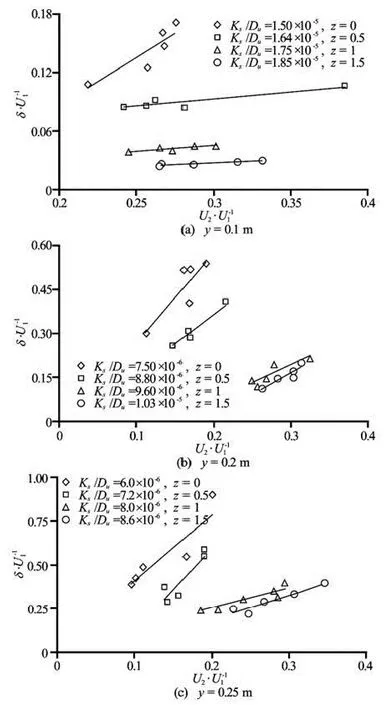
Fig.12 Variation of Secondary Circulation strength with velocity ratios
3. Conclusion
In this research, the flow patterns in a 90ointake has been investigated at four different bank slopes ofz=0, 0.5, 1, and 1.5. Both the experimental set-up and the numerical model of SSIIM 2 have been used to collect enough data. Results show that in laboratory conditions the diversion flow ratio atz=1 andz=1.5increase considerably against the vertical bank. The stream tube width is in direct proportion to the diversion flow ratio. With the same diversion flow ratio, the inclination of the bank makes the stream tube width decrease near the bed and increase on the surface. Comparing values of stream tube width for different slopes shows that atz=1 it is minimal in different layers. The secondary strength increases while relative velocity increases, and it decreases when roughness ratio increases. Also, the inclination of bankleads to a decline in secondary flow strength in the intake channel. The final conclusion is that inclining the channel banks can decrease the amount of sediment entering the intake.
[1] HALTIGIN T. W., BIRON P. M. and LAPOINTE M. F. Predicting equilibrium scour-hole geometry near angled stream deflectors using a three-dimensional numerical flow model[J].Journal of Hydraulic Engineering, ASCE,2007, 133(8): 983-988.
[2] SMITH H. D., FOSTER D. L. Modeling of flow around a cylinder over a scoured bed[J].Journal of Waterway, Port, Coastal, and Ocean Engineering,2005, 131(1): 14-24.
[3] NAZARZADEH R., KIAMANESH H. and HEDAYAT N. Investigating the sedimentation process using SSIIM 3D–A case of the Hamidieh Diversion dam in Iran[C].Proceedings of the WASET Conference.Paris, France, 2011.
[4] KOKEN M. Coherent structures around isolated spur dikes at various approach flow angles[J].Journal of Hydraulic Research,2011, 49(6): 736-743.
[5] HAN S. S., RAMAMURTHY A. S. and BIRON P. M. Characteristics of flow around open channel 90° bends with vanes[J].Journal of Irrigation and Drainage Engineering,2011, 137(10): 668-676.
[6] HUA Zu-lin, GU Li and CHU Ke-jian . Experiments of three-dimensional flow structure in braided rivers[J].Journal of Hydrodynamics,2009, 21(2): 228-237.
[7] HUANG Sui-liang, JIA Ya-fei and CHAN Hsun-chuan et al. Three-dimensional numerical modeling of secondary flows in a wide curved channel[J].Journal of Hydrodynamics,2009, 21(6): 758-766.
[8] BRADBROOK K. F., LANE S. N. and RICHARDS K. S. Numerical simulation of three-dimensional, timeaveraged flow structure at river channel confluences[J].Water Resource Research,2000, 36(9): 2731-2746.
[9] ABDERREZZAK K. E. L., LEWICKI L. and PAQUIER A. et al. Division of critical flow at three-branch openchannel intersection[J].Journal of Hydraulic Research,2011, 49(2): 231-238.
[10] NANIA L. S., GÓMEZ M. and DOLZ J. et al. Experimental study of subcritical dividing flow in an equalwidth, four-branch junction[J].Journal of Hydraulic Engineering, ASCE,2011, 137(10): 1298-1305.
[11] MIGNOT E., RIVIE`RE N. and PERKINS R. et al. Flow patterns in a four branches junction with supercritical flow[J].Journal of Hydraulic Engineering, ASCE,2008, 134(6): 701-713.
[12] KESSERWANI V., VAZQUEZ J. and RIVIÈRE N. et al. New approach for predicting flow bifurcation at right-angled open-channel junction[J].Journal of Hydraulic Engineering, ASCE,2010, 136(9): 662-668.
[13] HUANG J., WEBER L. J. and LAI Y. G. Three-dimensional numerical study of flows in open-channel junctions[J].Journal of Hydraulic Engineering, ASCE,2002, 128(3): 268-280.
[14] LI C., ZENG C. 3D numerical modelling of flow divisions at open channel junctions with or without vegetation[J].Advances in Water Resources,2009, 32(1): 49-60.
[15] NEARY V. S., ODGAARD A. J. Three-dimensional flow structure at open-channel diversions[J].Journal of Hydraulic Engineering, ASCE,1993, 119(11): 1223-1230.
[16] NEARY V., SOTIROPOULOS F. and ODGAARD A. J. Three-dimensional numerical model of lateral-intake in flows[J].Journal of Hydraulic Engineering, ASCE,1999, 125(2): 126-140.
[17] RAUDKIVI A. J.Sedimentation, exclusion and removal of sediment from diverted water[M]. IAHR, 1993, 164.
[18] ODGAARD A. J.River training and sediment management with submerged vanes[M]. ASCE Publisher, 2009, 171.
[19] HSU C. C., TANG C. J. and LEE W. J. et al. Subcritical 90oequal-width open-channel dividing flow[J].Journal of Hydraulic Engineering, ASCE,2002, 128(7): 716-720.
[20] KUBIT O., ETTEMA R. Debris-and ice-skimming booms at riverside diversions[J].Journal of Hydraulic Engineering, ASCE,, 2001, 127(6): 489-498.
[21] FAN Y., CHEN H. and GUO J. Study on diversion angle effect of lateral intake flow[C].Proceedings of 33th IAHR Congress: Water Engineering for a Sustainable Environment.Vancouver, Canada, 2009, 4509-4516.
[22] OMIDBEIGI M. A., AYYOUBZADEH S. A. and SAFARZADEH A. Experimental and numerical investigations of velocity field and bed shear stresses in a channel with lateral intake[C].Proceedings of 33th IAHR Congress: Water Engineering for a Sustainable Environment.. Vancouver, Canada, 2009, 1284-1291.
[23] RAMAMURTHY A. S., QU J. and VO D. Numerical and experimental study of dividing open-channel flows[J].Journal of Hydraulic Engineering, ASCE,2007, 133(10): 1135-1144.
[24] ABASSI A. A., GHODSIAN M.and HABIBI M. et al. Experimental investigation on sediment control in lateral intake using sill[C].Proceedings of 13th IAHRAPD Congress.Singapore, 2002, 230-233.
[25] OLSEN N. R. B. SSIIM users’manual[R]. Trondheim, Norwegian: The Norwegian University of Science and Technology, 2004.
[26] OLSEN N. R. B. CFD algorithms for hydraulic and sedimentation engineering[R]. Trondheim, Norwegian: The Norwegian University of Science and Technology, 2004.
10.1016/S1001-6058(14)60055-X
* Biography: SEYEDIAN Seyed Morteza (1982-), Male, Ph. D., Assistant Professor
杂志排行
水动力学研究与进展 B辑的其它文章
- Numerical simulation of landslide-generated impulse wave*
- A random walk simulation of scalar mixing in flows through submerged vegetations*
- Scaling of maximum probability density function of velocity increments in turbulent Rayleigh-Bénard convection*
- Dispersion in oscillatory electro-osmotic flow through a parallel-plate channel with kinetic sorptive exchange at walls*
- Evaluation of the use of surrogateLaminaria digitatain eco-hydraulic laboratory experiments*
- A numerical study on dispersion of particles from the surface of a circular cylinder placed in a gas flow using discrete vortex method*
