Lattice design and optimization of the SSRF storage ring with super-bends
2014-04-24TIANShunQiang田顺强JIANGBoCheng姜伯承ZHOUQiaoGen周巧根LENGYongBin冷用斌andZHAOZhenTang赵振堂
TIAN Shun-Qiang(田顺强),JIANG Bo-Cheng(姜伯承),ZHOU Qiao-Gen(周巧根),LENG Yong-Bin(冷用斌),and ZHAO Zhen-Tang(赵振堂)
1Shanghai Institute of Applied Physics,Chinese Academy of Sciences,Shanghai 201800,China
Lattice design and optimization of the SSRF storage ring with super-bends
TIAN Shun-Qiang(田顺强),1,∗JIANG Bo-Cheng(姜伯承),1ZHOU Qiao-Gen(周巧根),1LENG Yong-Bin(冷用斌),1and ZHAO Zhen-Tang(赵振堂)1
1Shanghai Institute of Applied Physics,Chinese Academy of Sciences,Shanghai 201800,China
In the near future,the Phase-II beamline project of Shanghai Synchrotron Radiation Facility(SSRF)will be implemented and some dipoles in the storage ring will be replaced by high f i eld dipoles(super-bend),so as to leave room for short straight sections.In this way,the brightness of the hard x-ray emitted from the super-bends can be enhanced,and more insertion devices can be installed.In this paper,super-bends of two lengths are discussed and the corresponding lattices are presented.
Shanghai Synchrotron Radiation Facility(SSRF),Super-bend,Lattice design,Nonlinear optimization
I.INTRODUCTION
Increased user demands for high brightness hard x-rays(20–40 keV)have been seen in recent years,while straight sections to install insertion devices(e.g.superconducting wigglers for hard x-rays)are often limited in a synchrotron radiation light sources.Because the critical photon energy(εC,in keV)emitted from dipoles increases with the bending fi eld(B,in T) and beam energy(E0,in GeV)asεC=0.665[1],much attention is paid to increasing the bending fi eld for high brightness hard x-rays in the synchrotron radiation light sources of moderate beam energy.In the early 1990s,BINP developed a superconducting bending magnet with working fi eld of 6T,for emitting hard X-rays in a proposed compact synchrotron radiation light source[2].In 2001,aimed at realizing high brightness hard x-ray production,for the fi rst time ALS replaced three normal dipoles with superconducting bending magnets at a fi eld of over 5T[3].This did show a great increase in super-bend availability and capacity.
As shown in Table 1,more and more super-bends are built or proposed at a number of synchrotron radiation light sources (BESSY-II[2],SLS[4],DIAMOND[5],and some lowenergy compact rings[6–8]).Besides,SIRIUS[9]in Brazil plans to add a high- fi eld slice in the center of bending magnets so as to reach up to 12keV of the critical photon energy.Light sources of about 3.0GeV in beam energy use room temperature bending magnets at about 3T to reach about 15keV in the critical photon energy and photon energy of 20–40keV is available.
The Shanghai Synchrotron Radiation Facility(SSRF),a 3.5GeV third generation intermediate-energy light source,has been open for users since May 2009[10,11].The SSRF storage ring is based on Double-Bend-Achromatic(DBA) cell[12].The critical photon energy from the dipoles is about 10.3keV.By the super-bend replacements,the brightness or fl ux of the hard X-rays can be signi fi cantly enhanced.As an example,Fig.1 shows that the critical photon energy increases to 24.9keV with a super-bend of 0.6m in path length and 3.0543T in steering fi eld.

Fig.1.(Color online)Photon spectrum of normal bend and superbend(3.05T)in SSRF.
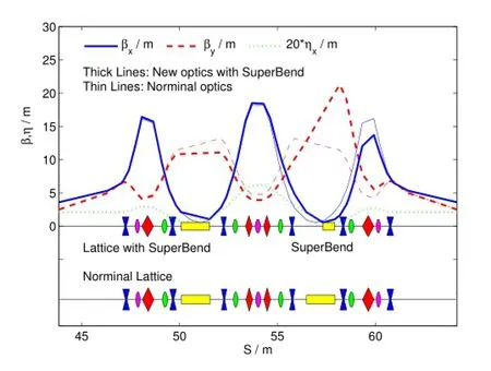
Fig.2.(Color online)Optics of the single super-bend lattice.
Shortening the dipoles provides a possibility of adding straight sections in the storage ring.By replacing two normal dipoles with two super-bends in one DBA cell,an insertiondevice can be installed at the cell center,as in the SOELILlattice[13].The number of ID straight sections is limited in SSRF,and a detailed study of this scheme is done for the SSRF phase-II beamline project.The machine performance is maintained as good as possible with the current hardware,such as the RF capability,maximum strength of the quadrupole and the sextupole.

TABLE 1.List of light sources with super-bends(SC,super conducting magnet;RT,room temperature magnet;PM,permanent magnet;NB, normal bend;CJSR,Central Japan Synchrotron Radiation Facility)

Fig.3.(Color online)Dynamic aperture,frequency maps,βfunction variation and tune shift of the single super-bend lattice.

TABLE 2.Beam parameters of different schemes(S-B,super-bend;LSS,long straight section;SSS,standard straight section;NSS,new straight section)at 3.5GeV of beam energy and 200mA of beam current

Fig.4.(Color online)DBA cell reconstruction and their locations in the SSRF storage ring.
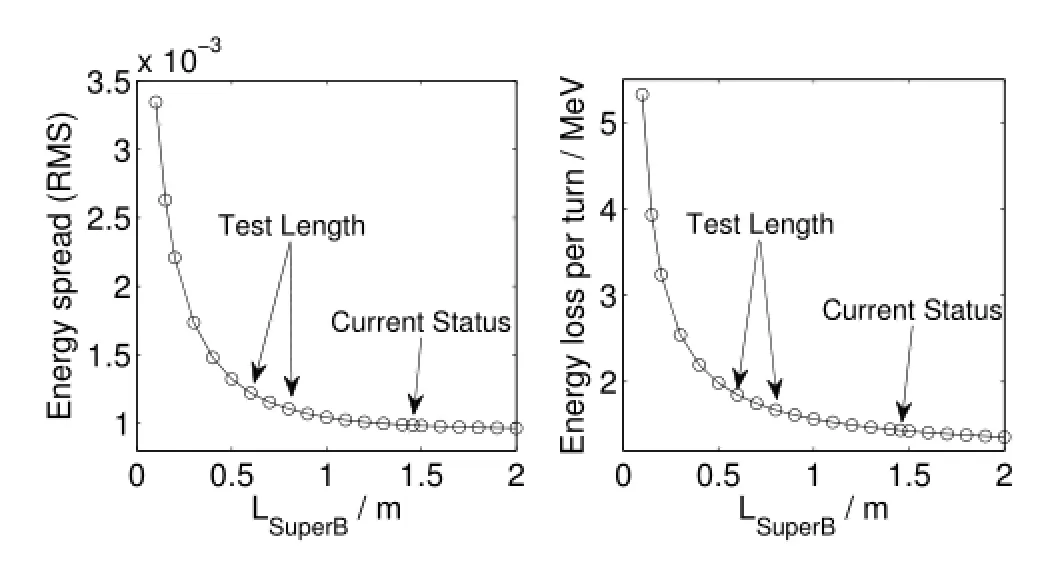
Fig.5.Energy spread and energy loss per turn as a function of the path length in the super-bend.
The challenges in the super-bend approach of SSRF include 1)lattice design and beam dynamics optimization for maintaining machine performance;2)design,fabrication,and installation of the super-bend;3)associated need to control errors in f i eld and the alignment;4)instability of the power supply,which can induce orbit jitter and beam energy vibration; 5)possible changes to the vacuum system;and 6)increase of the beam energy loss and the compensation capability of the RF system.In this paper,we report the results about the lattice design and beam dynamics,and a preliminary design of the super-bend.The cases of a single super-bend and eight superbends are discussed in Sec.II and Sec.III,respectively,and a preliminary design for super-bend magnet is given in Sec.IV.
II.SINGLE SUPER-BEND LATTICE
At f i rst,one normal dipole in the central DBA cell of a super-period in the storage ring is replaced by a super-bend of 0.6m in beam path and 3.0543T in steering f i eld.The ten quadrupoles in this cell are individually adjusted for optics matching.Thematchingprocesskeepsallthelinearopticalparameters of the source points,includingβx,βy,ηand their divergences.Because of the periodicity degeneration,a nonlinear resonance becomes stronger nearby the nominal working point of 22.220(H)and 11.290(V),which shifts to 22.220(H) and 11.276(V).Fig.2 plots the linear optics and shows the lattice change in this cell.The beam parameters are summarized in Table 2.Fig.3 shows the re-optimized nonlinear dynamics,including on-and off-momentum dynamic apertures,frequency maps[14–16],beta function variation,and tune shift with energy deviation.The chromaticity is corrected to 1 in both transverse planes,and the other cases are of the same. The natural emittance and energy spread increase a little,and the effective emittance along the ring increases by 5%with respect to the nominal optics.The beam energy loss per turn increases by about 4%,which can be compensated easily by the current RF system.Degradation of the dynamic acceptance is due to the symmetry broken.However,this solution is of the high injection eff i ciency and long beam lifetime.
III.EIGHT SUPER-BEND LATTICE
As shown in the left of Fig.4,by replacing the two dipoles in a DBA cell with the super-bends,and making the magnets in the arc close to the super-bends,an additional straight section is formed.We propose to replace eight normal dipoles in four DBA cells to form four more straight sections(Fig.4 in the right).The new straight section should be longer than 2m(thelonger,the better)for installing a short insertion device.

Fig.6.(Color online)Linear optics of one super-period in the 0.6m-length super-bend lattice.

Fig.7.(Color online)Dynamic aperture,frequency maps,βvariation and tune shift of the 0.6m-length super-bend lattice.
Figure 5 plots the energy spread and the energy loss per turn as a function of the beam path length in the super-bend in this case.At the beam current of 300mA,the RF system can support~2MeV per turn of the energy loss,which includes radiation from dipoles and IDs.So,the beam path length in the super-bend must be longer than 0.5m.The energy spread has a component of the effective emittance in the source point[17,18].For a high photon brightness,it should be low enough.The super-bend path length of 0.6m and 0.8m are considered(Fig.5).The 0.8m-length super-bend has a steering f i eld of 2.2907T,with the critical photon energy of 18.7keV.
When the working points are the same as the nominal one, the natural emittance increases up to about 5nmrad in the 0.6m-length super-bend lattice.Due to the large energy spread and natural emittance,the effective emittance increases by about 40%with respect to the nominal optics.The brightness decreases with increasing effective emittance.To avoid this, the horizontal working point is increased by one unit.The horizontal beta function at the injection point increases to 16m in order to get suff i cient dynamic aperture.Fig.6 plots the linear optics and Fig.7 gives the nonlinear optimal results.The beam parameters are summarized in Table 2.The natural emittanceis3.62nmrad,andtheeffectiveemittanceinthestandard straight section is 5.29nmrad,being just 2%higher than thenominal optics.The dynamic aperture is suff i cient to reach high injection eff i ciency.

Fig.8.(Color online)Linear optics of one super-period in the 0.8m-length super-bend lattice.
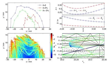
Fig.9.(Color online)Dynamic aperture,frequency maps,βvariation and tune shift of the 0.8m-length super-bend lattice.
The large energy loss per turn in the 0.6m-length superbend lattice makes it diff i cult to store 300mA beam current on the current RF system,as the SSRF storage ring has many insertion devices.Using the 0.6m-length super-bend lattice, the beam energy shall be 3.0GeV,rather than 3.5GeV,while using the 0.8m-length super-bend lattice,the energy loss per turn is just 1.670MeV at 3.5GeV.Fig.8 plots the linear optics in one super-period and and Fig.9 gives the nonlinear optimal results.The beam parameters are summarized in Table 2.The working point of this lattice is 23.23(H),11.31(V),the same as the 0.6m-length super-bend lattice.The natural emittance is 3.51nmrad,and the effective emittance in standard straight section is reduced to be 4.915nmrad.The frequency maps show a resonance-free interior part in the dynamic aperture, which is benef i cial to reach high injection eff i ciency.
IV.PRELIMINARY MAGNET DESIGN FOR SUPER-BEND
All of the three schemes of the super-bend are of nice beam dynamics,being applicable in machine operation.The 0.8mlength super-bend lattice is easy to keep the effective emittanceand the photon brightness from IDs as the nominal one,and the energy loss per turn is moderate to the current RF system at 3.5GeV,hence a good scheme for the SSRF lattice upgrade.

Fig.10.(Color online)General view of the super-bend design.
However,due to the limited space for the super-bend,it is diff i cult to design a super-bend with good f i eld quality.A super-bend can be a permanent magnet,superconducting magnet,or electromagnet.A permanent magnet suffers from demagnetization by beam loss,and corresponding nonuniformity among the super-bends.A superconducting magnet,which is expensive,is not necessary for a steering f i eld of just 2~3T for the SSRF storage ring.Therefor,an electromagnet is still a good option.Fig.10 shows a preliminary magnet design with H-frame yoke,and Table 3 summarizes the main parameters.The peak f i eld is 2.4T,and the good f i eld region is about±18mm,which is appropriate to the machine operation with the upgraded lattice.
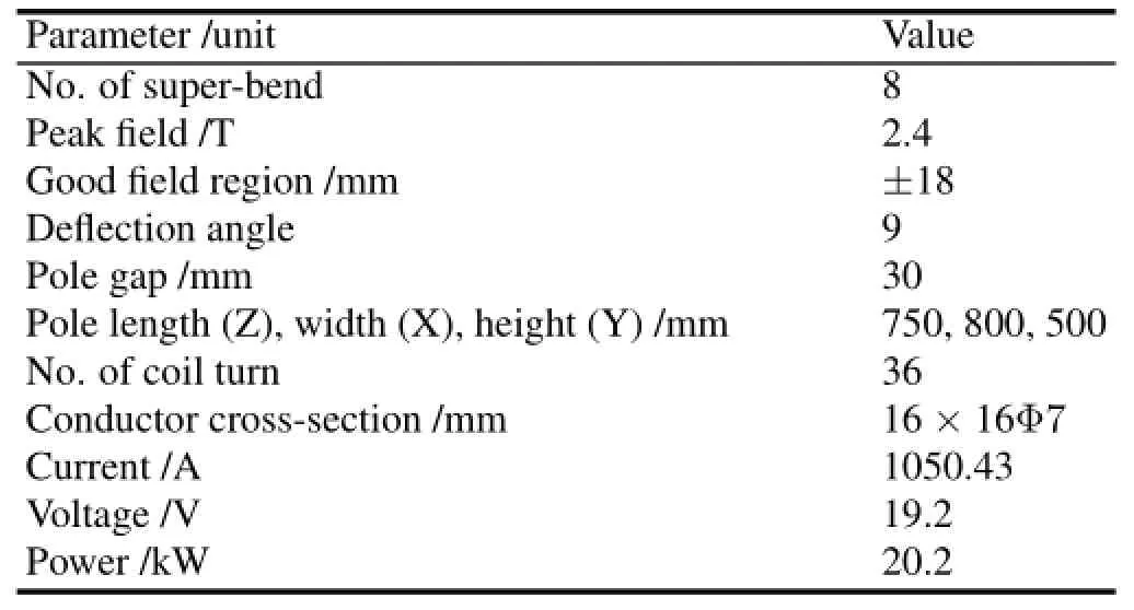
TABLE 3.Main parameters of super-bend
V.CONCLUSION
Different schemes of the lattice upgrade at SSRF with the super-bend are discussed.They include single super-bend lattice,eight 0.6m-and 0.8m-length super-bend lattice.The single super-bend lattice focuses on the usage of high photon brightness,whiletheeightsuper-bendlatticeschemesprovides four short straight sections of 2m length,which is attractive to SSRF.The 0.6m-length super-bend lattice suffers from high energy loss per turn,and is appropriate at 3.0GeV beam energy.The 0.8m-length super-bend lattice is a better solution in the current conditions,and a preliminary magnet design for this scheme is presented.After careful optimization,the beam emittance of all the three schemes is very close to the nominal one,and the dynamic acceptance can fulf i ll eff i cient injection and long beam lifetime.
[1]Chao A W.Handbook of Accelerator Physics and Engineering, 1999208:World Scientif i c.
[2]Batrakov A M,Khruschev S V,Kraemer D,et al.Nucl Instrum Methods Phys Res A,2005,543:35–41.
[3]Robin D,Krupnick J,Schlueter R,et al.Nucl Instrum Methods Phys Res Sect A 2005,538:65–92.
[4]Gabard A,George D,Negrazus M,et al.in Proceedings of IPAC2011,San Sebastian,Spain,2011,3038–3040.
[5]Walker R P,Bartolini R,Cox M P,et al.in Proceedings of IPAC2011,San Sebastian,Spain,2011,3059–3061.
[6]Antokhin E I,Gvozdev A A,Kulipanov G N,et al.in Proceedings of APAC 2007,Indore,India,127–129.
[7]Antokhin E I,Gvozdev A A,Kulipanov G N,et al.Nucl Instrum Methods Phys Res A,2007,575:1–6.
[8]Yamamoto N,Takashima Y,Hosaka M,et al.in Proceedings of IPAC2011,San Sebastian,Spain,2011,2987–2989.
[9]Liu L,Basilio R,Citadini J F,et al.in Proceedings of IPAC2011, San Sebastian,Spain,2011,931–933.
[10]Xu H J and Zhao Z T.Nucl Sci Tech,2008,19:1–6.
[11]Zhao Z T,Xu H J,Ding H.in Proceedings of PAC09,Vancouver, BC,Canada,2009,55–57.
[12]Liu G M,Dai Z M,Li H H,et al.High Energy Physics and Nuclear Physics,2006,30,Supp.I,144–146.
[13]Nadji A,Besson J C,Betinelli P,et al.in Proceedings of EPAC2006,Edinburgh,Scotland,2006,3284–3286.
[14]Laskar J.in Proceedings of PAC2003,Portland,USA,2003, 378–382.
[15]Robin D,Steier C,Laskar J,et al.Phys Rev Letters,2000,85(3): 558–561.
[16]Nadolski L and Laskar J.Phys Rev Special Topics A&B,2003,6:114801.
[17]Tanaka H and Ando A.Nucl Instrum Methods Phys Res Sect A, 1996,369:312–321.
[18]Lee S Y.Phys Rev E,1996,54(2):1940–1944.
10.13538/j.1001-8042/nst.25.010102
(Received August 22,2013;accepted in revised form November 26,2013;published online February 20,2014)
∗Corresponding author,tianshunqiang@sinap.ac.cn
杂志排行
Nuclear Science and Techniques的其它文章
- Using activation method to measure neutron spectrum in an irradiation chamber of a research reactor∗
- A neural network to predict reactor core behaviors∗
- Research on GPU-accelerated algorithm in 3D f i nite difference neutron diffusion calculation method∗
- Development of a three dimension multi-physics code for molten salt fast reactor∗
- Performance simulation and structure design of Binode CdZnTe gamma-ray detector
- Effectiveness and failure modes of error correcting code in industrial 65 nm CMOS SRAMs exposed to heavy ions∗