Frequency Domain Based Solution for Certain Class of Wave Equations:An exhaustive study of Numerical Solutions
2014-04-17VinitaChellappanGopalakrishnanandMani
Vinita Chellappan,S.Gopalakrishnanand V.Mani
1 Introduction
In this paper we discuss the numerical solution of partial differential equations(PDEs)using frequency domain approach for the following four classes of problems such as:
Problem(i)/Class(i):A cantilever beam of uniform cross-section.
Problem(ii)/Class(ii):A cantilever beam of varying cross-section.
Problem(iii)/Class(iii):A Timoshenko beam of uniform cross-section.
Problem(iv)/Class(iv):Timoshenko beam of varying cross-section.
Problem(i)is a second order PDE in one variable with constant coefficient,for which exact solution is available.Problem(ii)is a second order PDE in one variable with varying coefficients for which exact solution is available in the form of Bessel functions.The Timoshenko beam(Problem(iii))is a second order coupled PDE with constant coefficients, for which exact solution is available.Problem((iv))is coupled second order PDE in two variables with varying coefficients.However,for Problem(iv)exact solution is not available.Problem(iii)and(iv)when decoupled leads to a fourth order PDE.We solve all the four problems using spectral methods.Numerical methods such as the Galerkin approach,Petrov-Galerkin approach,Method of Moments and the Pseudo-spectral approach in frequency domain are also formulated for all the above problems.The numerical methods in frequency domain are validated for problems for which exact solution is available(Problem(i),(ii)and(iii)).We then obtain solution to Problem(iv)numerically.Various numerical methods are devised and are avialable in literature for the solution of PDEs of which the finite element methods,finite volume method,spectral method and Meshfree methods are quite popular.Solution of partial differential equations(PDE)in time domain using spectral function approximation in the spatial domain and then time marching in the temporal domain is quite popular[Boyd(2000),Cohen(2002)].The time domain solution has been applied for solution of a class of Hamilton Jacobi Bellman equation called the Eikonal equation[Salehi and Dehghan(2012)],a generalised Kuramoto Sivashinsky(GKS)equation[Khater and Temsah(2008)],for a Heterogeneous Porous Media Flow[Black(1995)]etc.,where different spectral methods are used for spatial discretisation.
An accuracy of finite element solutions for 3-D Timoshenko beams which is obtained using a co-rotational formulation is studied in[Iura,Suetake,and Atluri(2003)],where it is shown that the solutions converge to the exact beam theory as the number of elements increases.A number of numerical studies to deal with the 4thorder problem of thin beams like the meshless local Petrov Galerkin methods(MLPG)[Atluri,Cho,and Kim(1999)],where the beams under various loading and boundary conditions are analysed and compared with the analytical solution.A 4thorder differential equation is used in[Atluri and Shen(2005)]to show that various mixed MLPG methods are cost effective.Also,MLPG methods are used in[Long and Atluri(2002)]for solving the bending problem of a thin plate using least square approximation to interpolate the solution variables.
The Chebyshev collocation method for solution of simple ordinary differential equations with examples is discussed in detail in[Saravi,Babolian,England,and Bromilow(2008)].They have compared the results with the Adams method and has shown that the collocation method gives better rate of convergence compared to Adams method.In[Salehi and Dehghan(2012)],the Eikonal equation,which is a nonlinear partial differential equation for which exact solutions are usually difficult to obtain is numerically solved using Legendre pseudo-spectral viscosity techniques to discretise the problem in space.In[Khater and Temsah(2008)],the Chebyshev-spectral collocation method is used for spatial discretisation of the GKS equation.The spectral element technique in time domain,where the test function is different from the approximating polynomial is discussed in detail in[Black(1995)].In this Petrov-Galerkin method is used for the spatial discretisation of a Heterogeneous Porous Media Flow and Adams-Bashforth/Crank Nicholson Scheme is used for temporal discretisation.
Here,in this paper we consider the spectral element method in frequency domain for the numerical solution of all the four problems.
Spectral methods using Fourier transforms for wave propagation analysis were popularised by [Doyle (1999)] and more recently by [Gopalakrishnan, Chakraborty, and Mahapatra (2006)].Spectral finite element method(SFEM)is an effective tool used for solving wave propagation problems.It can be considered as a finite element method[Reddy(2005)]formulated in frequency domain.In SFEM,the governing partial differential equation is transformed in frequency domain using Discrete Fourier Transform(DFT)and is reduced to a set of ordinary differential equations(ODEs)with constant coefficients,with frequency as a parameter.The resulting ODE can be solved either analytically or numerically using spectral function approximation.Usually an exact solution to the governing ODEs in frequency domain is possible.In the absence of discontinuity,one single element is sufficient to handle a rod of any length.Spectral element for elementary rod[Doyle(1999)],elementary beam[Doyle and Farris(1990a,b)],Timoshenko beam[Gopalakrishnan,Martin,and Doyle(1992)],for elementary composite beam[Mahapatra and Gopalakrishnan(2003)],for functionally graded beams[Chakraborty and Gopalakrishnan(2003)]are reported in literature.In[Godinho and Soares Jr.(2013)]an optimised frequency domain iterative coupling algorithm is presented to analyze interacting acoustic elastodynamic models,which are discretized by sev-eral different numerical methods discussed above.To avoid ill posed problems arising due to frequency domain wave propagation analyses an optimal iterative procedure for solid-fluid interactions is given in[Godinho and Soares Jr.(2012)].In our recent study[Vinita,Gopalakrishnan,and Mani(2013)],the time domain analysis for solution of the wave equation for a uniform cross-section Cantilever beam is presented.In this study,the issues and challenges that arise in solving the wave equation in time domain and frequency domain is addressed.In our earlier study we have used both Lagrangian and Hermite interpolation for representation in spatial domain. In this paper, we use the Lagrangian interpolation for representation of the unknown function.
We discuss the performance of the four class of problems by considering:
(1)Effect of the number of FFT points used(Ns)
(2)Effect of the order of the polynomial(N)used for approximation
(3)Effect of the number of segments(elements)(S)used
(4)Effect of frequency(f)on the group speeds(cg)
(5)Observation of the shear mode and the bending mode for the Timoshenko beam by using a modulated pulse
(6)Effect of the taper parameter m on the group speeds(cg)for Problem(ii)and Problem(iv)
(7)Computation of group speeds for the Timoshenko beam with varying coefficient for which an analytical expression is not available
We can use the Fourier spectral analysis for all the four problems.But this introduces signal wrap around effects.One way of avoiding wrap around effect is by increasing the time windowT,or by providing an artificial damping to the system.Another way of avoiding wrap around effect is by using a throw off element which makes the transfer function complex,thereby providing sufficient damping to the system.Also,wrap around effects do not exist if one uses Wavelet transforms and Laplace transforms.The wavelet transform based finite element analysis for composite beams are discussed in[Mitra and Gopalakrishnan(2006)].The wavelet transform does not suffer from wrap around problems since the periodicity assumption is not used in constructing the transform,but lacks frequency resolution.It is shown that the wrap around effects are reduced as a result of taking the Laplace Transform of the unknown axial displacement in place of Fourier transform[Murthy,Gopalakrishnan,and Nair(2011)].Hence in our study,we have used the Laplace transform method for solution of the all the four problems.We also use Laplace spectral element method(LSEM)for an approximate solution to Problem(iv).
For approximate solution in frequency domain analysis, the set of ODEs in frequency domain is solved numerically using variational principles,by approximating in spatial domain using spectral functions like Chebyshev and Legendre polynomials.The method of weighted residuals[Reddy(2005)]is used for an approximate solution in the spatial domain.We also study the various numerical methods like Galerkin approach,Petrov-Galerkin approach,Method of Moments approach and the Collocation approach[Boyd(2000);Canuto,Quarteroni,Hussaini,and Zang(2006)].We compare all the numerical methods with the exact solution available for Problem(i),(ii)and(iii).For the Timoshenko beam with variable coefficients(Problem(iv)),we present the numerical solution.
We also obtain the group speed for varying taper parameterm,by varying the frequency of the input pulse.We then show that the modulated pulse is able to extract the shear mode and the bending mode of the Timoshenko beam.We also observe the effect of taper parametermon the shear mode for fixedεfor Problem(iv).
It is also shown that the group speeds of the shear mode and the bending modes vary with frequency and taper parametermfor the Timoshenko beam with varying coefficients(Problem(iv)).Since the computation of the group speeds is not possible analytically for the Timoshenko beam with varying cross-section,we use the numerical methods to compute the group speeds.We form an approximate expression for the computation of the group speed and the cut-off frequency for Problem(iv)),Finally,we show that the cut-off frequency disappears for largemforε>0 and increases for largemforε<0.
2 Problem description
We define all the four problems in detail.
2.1 Problem(i):Cantilever beam of uniform cross-section
The governing partial differential equation for the axial displacement(u(x,t)),in space and time of an undamped rod with uniform cross-sectionA0(Fig.1.a)),in a given domain defined by the wave equation,is a second order partial differential equation in one variable is given as,


Figure 1:Cantilever beam

Figure 2:Timoshenko beam
2.2 Problem(ii):Cantilever beam of varying cross-section
The governing partial differential equation for the axial displacement(u(x,t)),in space and time of an undamped rod with varying cross-sectionA(x),in a given domain defined by the wave equation,is a second order partial differential equation in one variable with varying coefficients as,

2.3 Problem(iii):Timoshenko beam of uniform cross-section
The Timoshenko beam is different from the Bernoulli beam as it also considers the shear deflection.The details of the derivation for the Timoshenko beam is given in[Doyle(1999);Reddy(2005)].
A Timoshenko beam of uniform cross-section is shown in(Fig.2.a).The height of the beam atx=0 ish(x)|x=0=h0.The heighth(x)is uniform throughout the length of the beam,withh(x)=h0,x∈[0,L].Thus,the area of cross-section and the moment of inertia is a function ofxand can be written as,

The Timoshenko beam leads to two partial differential equations in two variables given as,

Here,w(x,t)is the transverse deflection andφ(x,t)is the shear deflection.Also,for uniform cross-section and constant coefficients,A(x)=A0andI(x)=I0.The boundary conditions specified withA(L)=A0andI(L)=I0are,

2.4 Problem(iv):Timoshenko beam of varying cross-section


The partial differential equations in two variables for the Timoshenko beam with varying coefficients are the same as given by(Eq.4)and(Eq.5).The boundary conditions for the Timoshenko beam of varying cross-section are given by(Eq.6)and(Eq.7).

The initial conditions assumed for Problem(iii)and(iv)of Timoshenko beam are ratio.The boundary conditions atx=L,is either specified as a shear forceVLor a Moment forceMLas defined by(Eq.7).
For all the four problems,the axial force,FLin Problem(i)and(ii),the shear forceVLand Moment forceMLin(Eq.7)is taken either to be a Gaussian pulse or a modulated pulse given by:

Here,µis the mean andσ2is the variance.The pulsewidth is essentially controlled by the variance parameterσfor the Gaussian pulse.For the modulated pulse,fis the frequency andTpulseis the time period of the pulse.The forcing function(FL/VL/ML),in the form of a Gaussian pulse and a modulated pulse is shown in(Fig.3)and(Fig.4).
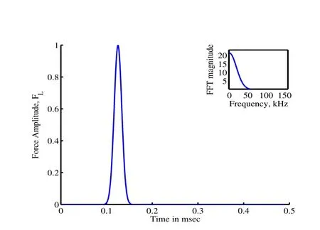
Figure 3:Forcing function,FLis a Gaussian pulse applied at the free end of the rod

Figure 4:Forcing function,VLis a modulated pulse applied at the free end of the rod
In the next section we present the exact solution of the cantilever beam and the Timoshenko beam in frequency domain.
3 Exact Solution in Frequency Domain

For Problem(iii)the exact solution for(Eq.4)and(Eq.5)is available in frequency domain.The difference between the rod and the beam is that the beam does not have a D’Alembert’s solution and the solution itself is dispersive[Doyle(1999)].Here we also consider a throw-off element attached at both the ends of the Timoshenko beam and we separate the shear mode and the bending mode.For Problem(iv),the exact solution for(Eq.4)and(Eq.5)is not available.We get the solution numerically and separate the shear mode and the bending mode for varying taper parametermandε.
Spectral methods using Fourier analysis have become very popular recently in wave propagation analysis.This is because,the Fourier transformation reduces the governing PDE into a set of ODEs and an analytical solution is possible for most of the 1-D waveguides.Spectral analysis using Fourier methods was first popularised in[Doyle(1999)]and a complete state of the art of spectral analysis is discussed in[Gopalakrishnan,Chakraborty,and Mahapatra(2006)].Finite element method formulated in the frequency domain is known as the Spectral Finite Element Method(SFEM).Fourier based spectral finite element method(FSEM)has become a very efficient tool for solving wave propagation problems,due to its ability to handle problems involving high frequency signals.Usually,in FSEM one element is sufficient to handle structures without discontinuities.Fourier analysis is prone to signal processing errors due to periodicity assumption of signals both in time and frequency domain.A detailed description of the Fourier analysis for the cantilever beam was done as an initial study and is given in[Vinita,Gopalakrishnan,and Mani(2013)].
In[Vinita,Gopalakrishnan,and Mani(2013)]we have considered a throw off element to avoid signal wrap around effects.If we allow some leakage of the signal response from the fixed boundary,it introduces an artificial damping so that good resolution in the time response signal is obtained.The leakage is modelled using an infinite element at the fixed end of the rod;also called a throw off element[Doyle(1999);Gopalakrishnan,Chakraborty,and Mahapatra(2006)].This makes the transfer function of the system in Problem(i)complex,indicating that the wave also attenuates as it propagates.That is,if the time window is large enough,the wraparound problems can be avoided.Problem(iii)is also modelled using a throw-off element attached at both the ends of the Timoshenko beam in order to avoid signal wrap around effects.Thus for an exact solution,we can also use the Fourier transform approach for the Timoshenko beam.
Another way of avoiding wrap around is by adding sufficient damping to the system by taking the Laplace transform of the signal instead of Fourier transform[Murthy,Gopalakrishnan,and Nair(2011)].It is well known[Lathi(1998)]that the Laplace Transform can be seen as the Fourier Transform of an exponentially windowed signal.So in this paper,we discuss only the Laplace transform approach for a solution in frequency domain.
3.1 Problem(i):Cantilever beam of uniform cross-section


3.2 Problem(ii):Cantilever beam of varying cross-section
For a cantilever beam with varying cross-section,we substitute the derivatives of the axial displacement in the governing(Eq.2),as,


3.3 Problem(iii):Timoshenko beam of uniform cross-section
For an exact solution,for the problem(iii),we first take the Laplace transform of the unknown functionw(x,t)andφ(x,t)asˆwn(x,sn)andˆφn(x,sn)as given in[Vinita,Gopalakrishnan,and Mani(2013)].The Laplace transform of the(Eq.4)and(Eq.5),leads to two sets of(Ns)ordinary differential equations in two variables with constant coefficient given by,

withA(x)=A0andI(x)=I0,and boundary conditions,


The above(Eq.22)has a non trivial solution only if|H(kn)|=0,which is given by the characteristic equation as,


Thus the exact solution for the ODEs defined by(Eq.17)and(Eq.18)for an uniform Timoshenko beam is given as,


3.3.1Throw off element:
We now consider a throw off element attached to both the ends of the Timoshenko beam.The use of throw off element for a uniform rod is discussed in[Vinita,Gopalakrishnan,and Mani(2013)].We obtain the shear and bending modes separately for the Timoshenko beam without reflections from the boundary for the exact case.The throw off element attached at the boundary of the Timoshenko beam is formulated by neglecting the reflected coefficientsBnandDnin(Eq.26)and(E-q.27).
For the infinite segment we assume an uniform cross-sectional area,A∞and moment of inertia,I∞equivalent to that at the boundaries(x=0 andx=L)of the beam.A throw off element attached at the boundary of a varying cross-section Timoshenko beam is shown in(Fig.2.b).Thus,the solution for the horizontal and shear deflection for the Timoshenko beam at infinite segments on either ends is given by,

Here the subscriptslandrstands for infinite segments attached at the left and right of the Timoshenko beam.The solution for the finite segment of Timoshenko beam is as given by(Eq.26)and(Eq.27).At the interface between the infinite and the

Note that for Problem(iii),the modeling using throw off element aids in formulation also using the Fourier transform approach.This is because use of a throw off element avoids signal wrap around problems,as there is no reflection from the boundaries.
3.4 Problem(iv):Timoshenko beam of varying cross-section
Timoshenko beam of varying cross-section does not have an exact solution.Here,we use numerical methods for the solution. We discuss the numerical solution using spectral functions such as Chebyshev polynomials,Legendre polynomials and the Normal polynomials later in the paper.We try the different numerical methods such as the Galerkin approach,Petrov-Galerkin approach,Method of Moments and the Pseudo-spectral/Collocation Method for a solution.
4 Derivation of the group speeds,phase speed and the corresponding time

4.1 Problem(i)and(ii):Cantilever beam of uniform and varying cross-section

4.2 Problem(iii):Timoshenko beam of uniform cross-section


4.3 Problem(iv):Timoshenko beam of varying cross-section
It is not possible to get the phase speeds and the group speeds exactly for the Timoshenko beam with varying area of cross-section.We get the group speeds numerically for varying taper parameterm,by varying the frequency of the input pulse.The variation of the group speeds with frequency is then plotted for both the shear mode and bending modes.The results are discussed later in the paper.
5 Numerical solution
In this paper,we analyse the performance of the numerical solution obtained using frequency domain analysis.For this,we first compare the numerical solution with the available exact solution for Problem(i),Problem(ii)and Problem(iii).For Problem(iv),as mentioned earlier,exact solution is not available,hence an approximate solution is obtained using the numerical methods.
5.0.1Solution approach
The fundamental approach to most of the numerical methods is the weighted residual technique[Reddy(2005)]and is discussed in[Vinita,Gopalakrishnan,and Mani(2013)],where in the domain of interest is split up into many sub elements there by constructing a grid or mesh of the domain.Each mesh has a definite number of grid points or nodes and the variation of the dependent variable is expressed in terms of the values at the grid points that make up the single sub element.Such a relation is known as the shape function.For an approximate solution,we use classical variational method,which leads to the Method of Weighted Residuals[Reddy(2005);Boyd(2000)]where the residual is made zero in a weighted integral sense.In this paper we discuss the weak form of the weighted integral form of the governing differential equation to obtain the solutions.
For all the four Problems(i)to(iv),we can use either Fourier,or Laplace transform to transform the corresponding PDEs to ODEs in frequency domain.In our study,we use the Laplace transform.For Problem(i)and(ii),(Eq.1)and(Eq.2)in time domain is given by(Eq.11)and(Eq.14)forn=0,1,...,Ns−1 in the Laplace domain.Similarly,for Problem(iii)and(iv),(Eq.4 and(Eq.5)in time domain are given by(Eq.17)and(Eq.18)forn=0,1,...,Ns−1 in the Laplace domain.
The weighted residual technique and the weak form formulation reduces(Eq.11)and(Eq.14)and the the corresponding(Eq.17)and(Eq.18)to the form respectively as,

where[K]and[M]are the stiffness and the mass matrix and[KD]is the dynamic the inverse Laplace transform.

Any numerical method including the weighted residual method in frequency domain require a grid(or elements).Over each grid(element),a set of solutions are assumed,which are synthesised over all elements to obtain global solution.The nature of the solution assumed in Weighted Residual technique determine the type of numerical method,which in turn fixes the nodal points on the grid.For spatial discretisation in frequency domain,we considerN+1 interpolation points(or grid points/nodes),whereNis the order of interpolating polynomial.The problem domain,[x0,xf]is divided intoNpartitions of equal or variable length,withN+1 interpolation points(or grid points/nodes).Thus,the unknown function in frequency domain,can be approximated using anNthorder polynomial function in the interval[x0,xf].The approximating function,approaches the exact solution in frequency domain asN→∞.The selection of the grid points and the polynomials for the approximation are briefly discussed in the next two sections.
5.1 Selection of Grid points or nodes
The grids are selected based upon quadrature rules.Quadrature rule depends on the type of method employed under Weighted Residual method to solve the problem.If we use the standard Galerkin procedure under Weighted Residual technique,we will normally use Gauss Quadrature rule to integrate to obtain the matrices[K],[M]and[KD]in(Eq.33).On the other hand if we choose orthogonal polynomials such as Chebyshev or Legendre polynomials as basis functions,then we will use Gauss Lobatto integration rule to obtain[K],[M]and[KD].The difference between the former and the latter integration is that in the latter,the integration points coincides with the nodal points,which will make[M]in(Eq.33)diagonal.
Thus,we can have Gauss,Gauss-Radau or Gauss Lobatto grids as given in[Canuto,Quarteroni,Hussaini,and Zang(2006)].The advantage of the above grids over uniform grid is that they have the distribution property that,they cluster around the endpoints of the interval.The Gauss-Lobatto grid points are found to have the least error.The Chebyshev Gauss Lobatto points,(CGL)are extensively used in earlier studies[Canuto,Quarteroni,Hussaini,and Zang(2006)],as the interpolation at the CGL nodes gives the closest approximation to a given function.Also,CGL points result in the avoidance of the Runge phenomenon[Canuto,Quarteroni,Hussaini,and Zang(2006)].Hence,CGL points are used in this paper.
The CGL points are the roots of the Chebyshev differential equation,and are giv-

5.2 Selection of trial and test functions

For the cantilever beam with uniform cross-section(Problem(i))and with varying cross-section(Problem(ii)),we have only one dependent variable,the axial displacement(u(x,t)).For the weighted form for Problem(i)and(ii),we consider the test function with the same units as the axial displacementvu(x).
For the Timoshenko beam with uniform cross-section(Problem(iii))and with varying cross-section(Problem(iv)),we have two dependent variables namely the horizontal deflection(w(x,t))and the shear deflection(φ(x,t)).Hence for Problem(iii)and(iv),we need to consider the test functions corresponding to the horizontal deflectionvw(x)and also the test function corresponding to the shear deflectionvφ(x).


Problem(iii)and(iv):Representation of horizontal deflection,shear deflectionand the test function


6 Weak form formulation
Thus,for a second order differential operatorL,we require that the function(u,w,φ)∈C1(0,L).Thus,we have larger solution subspace to search foru,wandφ.Another advantage is that,the weak form of a self adjoint operatorLleads to a symmetric matrix for[K],[M]and[KD]in(Eq.33).Computation with symmetric matrices are more efficient as special algorithms are available.Moreover,the boundary conditions are directly embedded in the weak form formulation.The weak form formulation in frequency domain and time domain approach is discussed in the next section.The weak form formulation and the solution to the wave equation for the cantilever beam of uniform cross-section(Problem(i))is given in detail in our technical report[Vinita,Gopalakrishnan,and Mani(2013)].The formulation of the varying case can also be obtained on similar lines.Hence in this section we consider only Problem(iii)and(iv).
6.1 Problem(iii)and(iv):Weak form formulation and solution to the weak form


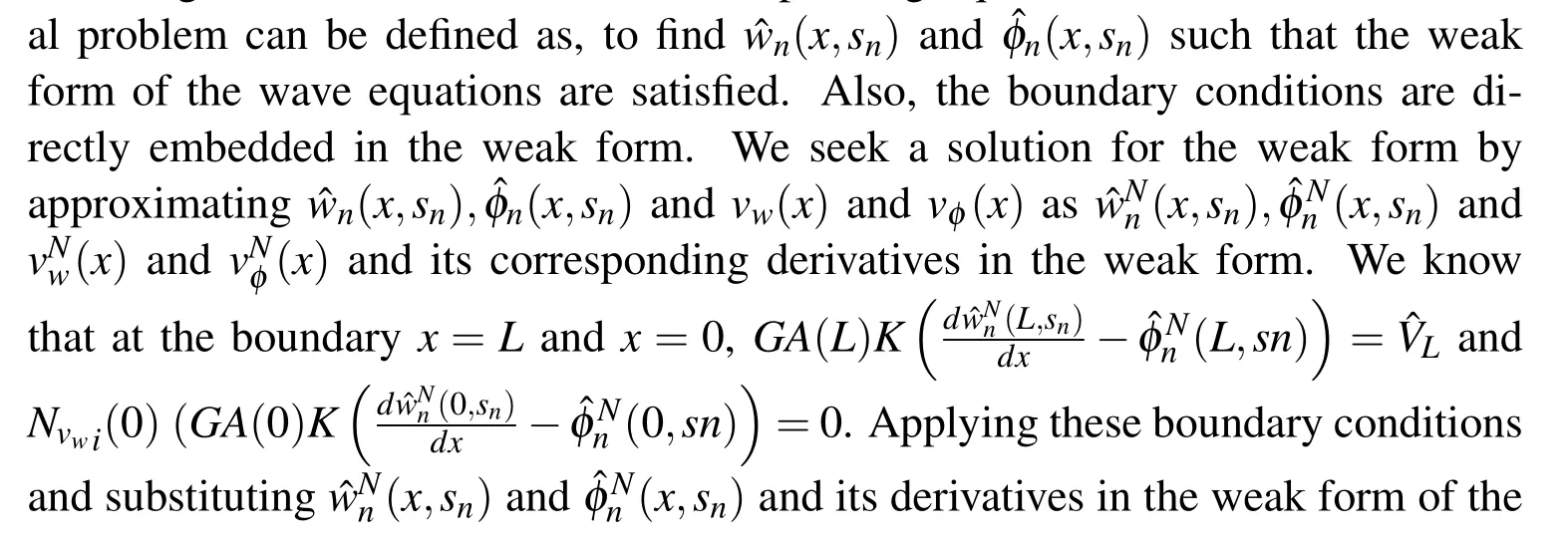

Herei=0,1,2,...,N.The boundary conditions are specified either as shear force

The solution to our problem,involves the following steps.

•Step 2:Define the matrices,KA,KI,MA,MG,MI,PandLas,

where,(.)ijand(.)ijare respectively the components of the corresponding matricesKA,KI,MA,MG,MI,PandL.


6.2 Collocation approach

The collocation approach for the cantilever beam with uniform cross-section is derived in detail in[Vinita,Gopalakrishnan,and Mani(2013)].In this section we discus sonly the collocation approach for the Timoshenko for varying cross-section.The collocation approach for the uniform cross-section can be derived directly from beam.


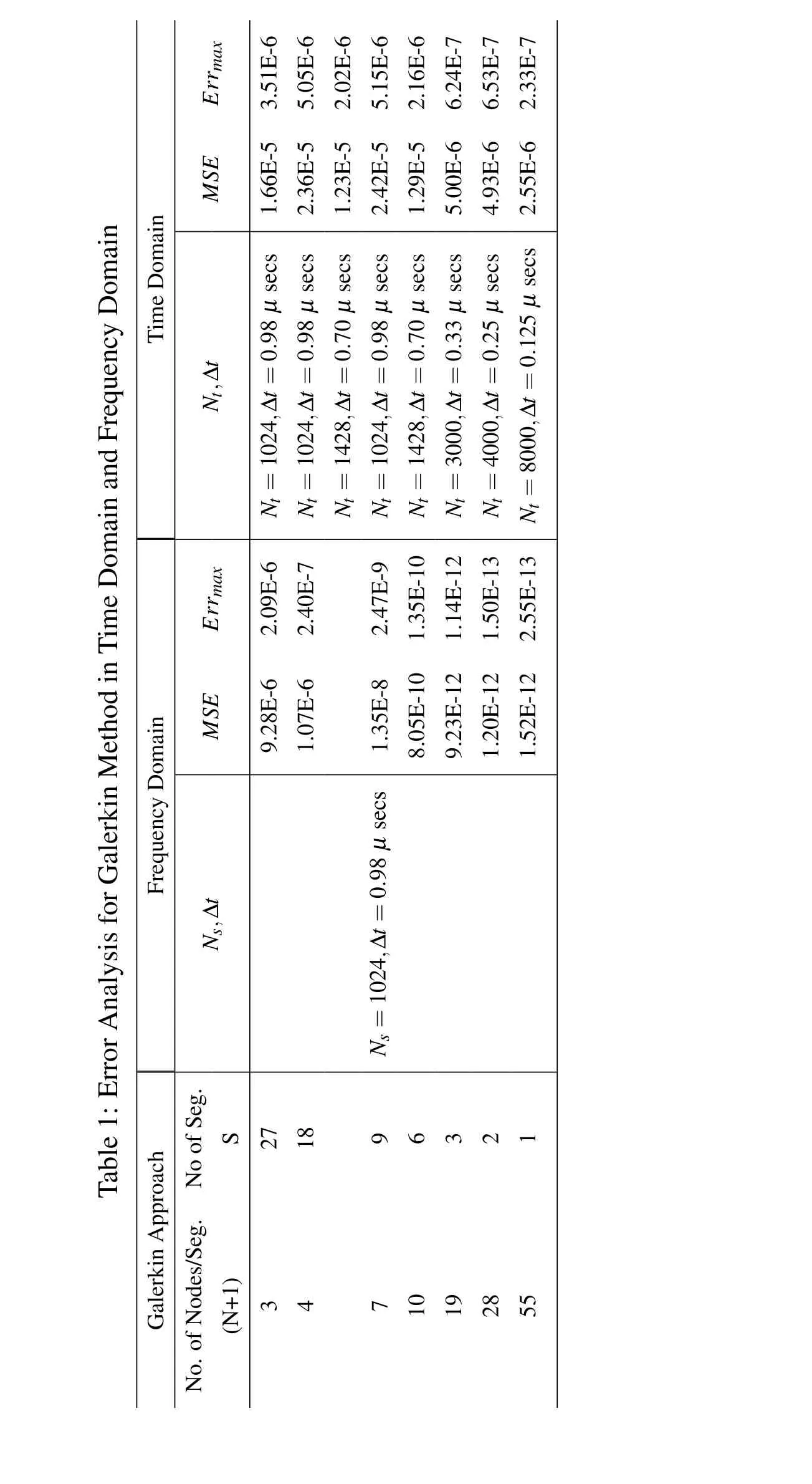
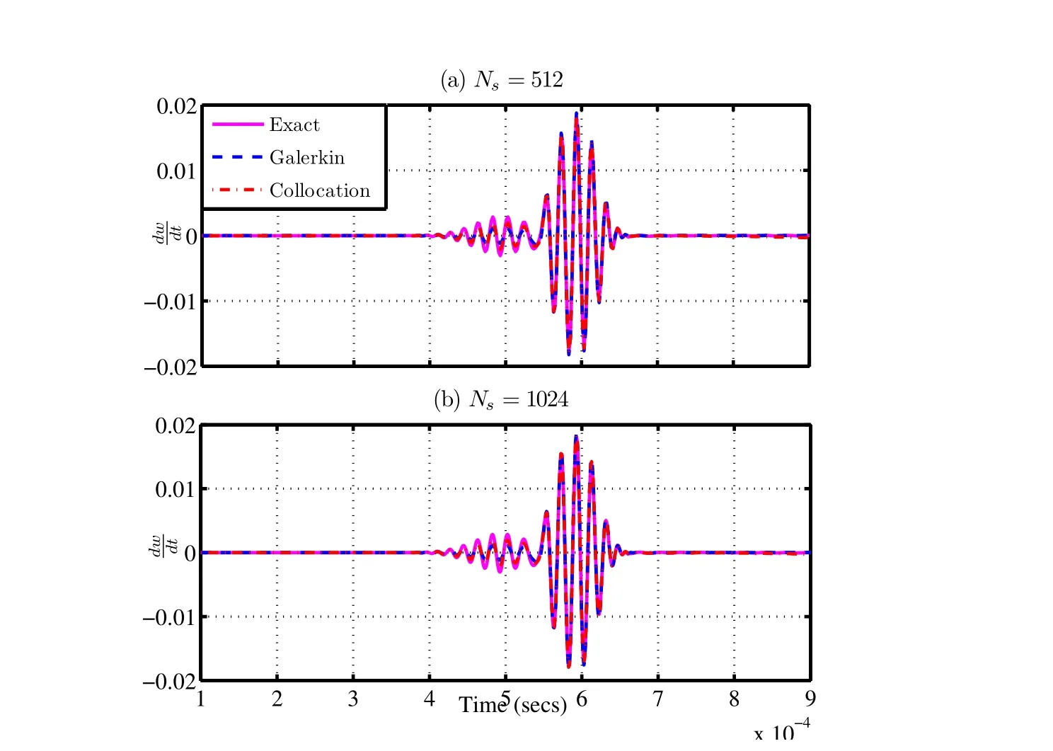
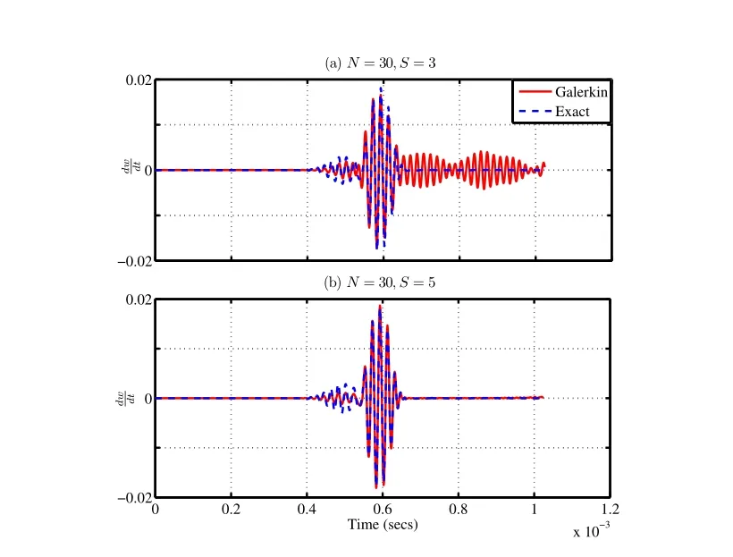
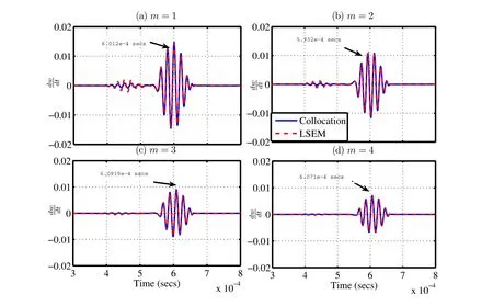
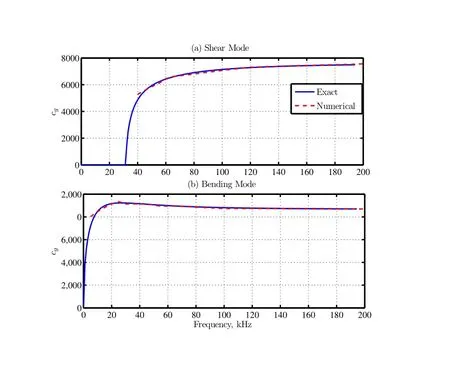
The weak form defined by(Eq.41)and(Eq.42),now reduces to the strong form of the solution defined at the collocation points 0 The important point here is that the equation satisfies for allxionly in(0,L),except at the boundary.Hence,we have to impose the boundary conditions: The residuals of the differential(Eq.17)and(Eq.18)for varying cross-section in frequency domain are given as, Comparing the residual in 0 In this section,we present the numerical results obtained for all the four problems(Problems(i)to(iv))obtained using different numerical methods such as Galerkin,Petrov-Galerkin,Method of Moments and the Pseudo-spectral method.The numerical results obtained is first compared with the problems for which exact solution is available(Problem(i)to(iii)).For Problem(i)and(ii),we discuss the effect of the number of FFT points(Ns),the number of segments(S)and the order of the polynomial(N)used for approximation.We then show the numerical results of Problem(ii)for different values of taper parametermand it is then compared with the exact solution. The numerical solution to Problem(iii)is also sought and compared with the exact solution available.We also separate the shear mode and the bending mode numerically for Problem(iii).The group speeds for Problems(i)to(iii)can be computed exactly.The group speed for Problem(i)and(ii)are constant and is independent of frequency,but for Problem(iii)and(iv),the group speeds vary with frequency.Also,the group speeds for Problem(iv)is not available analytically.Hence,we first determine numerically the group speeds for Problem(iii)for which the group speeds can be computed exactly.We then compare the numerical results with the exact results.Finally,for Problem(iv),we also plot the group speed with frequency by observing the group speeds numerically for the shear mode and bending mode for varying frequencies.We also observe that the group speeds vary with the taper parameterm.An approximate expression for calculating the cut-off frequency and the group speeds corresponding to the shear mode and the bending mode is also obtained. Figure 5:Effect of the Gaussian pulse and the Modulated pulse A comparitive study of the frequency domain(both Fourier transform and Laplace Transform method)and the time domain analysis for Problem(i)in detailed in[Vinita,Gopalakrishnan,and Mani(2013)].In the report we have used the Newmark integration scheme for time marching for Problem(i). However,the frequency domain approach using Discrete Fourier Transform leads to wrap around effects,which can be avoided either by increasing the time window,or by using a throw off element,by taking a Laplace transform or Wavelet transforms of the unknown function.In the case of the Laplace transform the damping factor is selected using the Wilcox and Wedepohl methods[Murthy,Gopalakrishnan,and Nair(2011)],which needs to be designed. For Collocation approach,theMSEandErrmaxfor CGL(Chebyshev Gauss Lobotto),LGL(Legendre Gauss Lobotto)and equidistant points are shown in(Tab.2).The Legendre polynomials were chosen as the trial function(φi).We see from Table(2)that CGL points have the least error.Thus,for all our analysis,CGL points were considered for the above reason.The details are studied in[Vinita,Gopalakrishnan,and Mani(2013)]. It is of interest to study the effect of the number of FFT points(Ns),number of segments(S),the order of the polynomial(N)required for approximation,the effect of taper parametermand the effect of frequencyf,for various numerical methods on the solution of the Cantilever beam and the Timoshenko beam. ? Table 2:Error Analysis for Collocation method considering different grid points 7.3.1Effect of Ns(Number of FFT points) The results for different FFT points for Problem(i)and(ii)for the Galerkin and Collocation method are compared with the exact solution and is shown in(Fig.6)and(Fig.7)respectively.In our approach we have considered the following:Ns=128,256,512 and 1024,N=4,S=12,Ng=SN+1=49,taper parameters for Problem(ii)-m=1 anda=0.5,trial function-Chebyshev.In order to increase the time window,sampling time is taken as∆t=3µseconds.It is observed that even forNs=128,the wrap around effect is avoided. Figure 6:Problem(i):Effect of Nsfor different FFT points(128,256,512 and 1024)with dt=3µsecs For Problem(iii),we consider the following:Ns=512 and 1024,N=30,S=8,Ng=SN+1=121,Length of the finite beamL=2 m,trial function-Legendre.In order to keep the time window constant,sampling time is∆t=2 and 1µseconds.The variation of the transverse velocity with time for different FFT points is plotted for Galerkin approach,and Collocation approach for Problem(iii)as shown in(Fig.8).We obtained similar results for the Petrov-Galerkin and Method of Moments approach,and hence not shown here. 7.3.2Effect of S(Number of segments) In the finite element analysis,the beam element length,Lis divided into finite element or segmentsS.AnNthorder polynomial approximation is used per segment.Thus,each segment will haveN+1 nodes.For a fixed degree of freedom(DOF),Ng,the number of segments(S)and the number nodes per segment(N+1)are selected such thatSN+1=Ng.This helps in selecting a polynomial of lower order.In order,to study the effect of the number of segments(S),we kept the order of polynomial(N)fixed in each segment and varied the number of segmentsS.Here,we have considered the following parameters for Problem(i)and(ii):Ns=512,∆t=1µseconds,order of the polynomial per segment,N=2,with number of nodes per segment,(N+1=3),S=8,16,32,64 withNg=SN+1=17,33,65,129.Taper parameters for Problem(ii)-m=1 anda=0.5,Trial function-Chebyshev.The variation of velocity with time is plotted for Galerkin and Collocation approach for Problem(i)and(ii)as shown in(Fig.9)and(Fig.10)respectively.The results are compared with the exact solution.Here,it is seen from this figure that in frequency domain analysis,the approximate solution approaches the exact solution as we increase the number of segments,when the order of the polynomial is low.For Problem(iii),we have considered the following parameters:Ns=1024,∆t=1µseconds,order of the polynomial per segment,N=30,with number of nodes per segment,(N+1=3),S=3,5,Ng=SN+1=91,151,Trial function-Chebyshev.The variation of transverse velocity with time is plotted for Galerkin and Collocation approach for Problem(iii)as shown in(Fig.11)and(Fig.12)respectively.The results are compared with the exact solution.Here,it is seen from this figure that in frequency domain analysis,the approximate solution approaches the exact solution as we increase the number of segments,when the order of the polynomial is low. Figure 7:Problem(ii):Effect of Nsfor different FFT points(128,256,512 and 1024)with dt=3µsecs Figure 8:Problem(iii):Effect of Nsfor different FFT points(512 and 1024)with dt=2 and 1µsecs Figure 9:Problem(i):Effect of S for N=3 Figure 10:Problem(ii):Effect of S for N=3 Figure 11:Problem(iii):Effect of S for N=30 for Galerkin approach Figure 12:Problem(iii):Effect of S for N=30 for Collocation approach 7.3.3Effect of N(order of the polynomial) To study the effect of the order of the polynomial(N),in each segment,we fix number of segments and vary the number of nodes per segment.For Problem(i)and(ii),we have considered the following parameters:Ns=512,∆t=1µseconds,order of the polynomial per segment,N=2,6,9,11,with number of nodes per segment,(N+1=3,7,10,12),S=8,Ng=SN+1=17,49,57,89,taper parameters for Problem(ii)-m=1 anda=0.5,Trial function-Chebyshev.The variation of velocity with time is plotted for Galerkin and Collocation approach for Problem(i)and(ii)as shown in(Fig.13)and(Fig.14)respectively.The results are compared with the exact solution. We have given a detailed study of the error analysis of the different numerical methods for Problem(i)in[Vinita,Gopalakrishnan,and Mani(2013)].To study the effect of the order of the polynomials(N),we considered the Collocation approach.The variation of mean squared error(MSE)withNgis shown in(Fig.15)and the variation of maximum error(Errmax)withNgis shown in(Fig.16).TheMSEandErrmaxdecreases as we start increasing the number of nodes per segment.As the order of the polynomial(N)increases per segment,the convergence rate also increases.These figures show an exponential convergence and the exponential decrease in error and is proportional to the order of the polynomials(N).For Problem(iii),we have considered the following parameters:Ns=1024,∆t=1µseconds,order of the polynomial per segment,N=20,27,with number of nodes per segment,(N+1=21,28),S=5,Ng=SN+1=101,136,Trial function-Chebyshev.The variation of velocity with time is plotted for Galerkin and Collocation approach for Problem(iii)as shown in(Fig.17)and(Fig.18).The results are compared with the exact solution.The(Fig.9)and(Fig.13),(Fig.10)and(Fig.14),(Fig.11)and(Fig.17)and(Fig.12)and(Fig.18)show that the approximating polynomial converges to the exact solution with lesser number of segments(S),for higher order of polynomial(N),taken per segment.We obtained similar results for the Petrov-Galerkin and Method of Moments approach,and hence not shown here. Figure 13:Problem(i):Effect of N for if xed number of segments(S=8) Figure 14:Problem(ii):Effect of N for if xed number segments(S=8) Figure 15:Probem(i):MSE for collocation approach for different order of polynomial Figure 16:Problem(i):Max.Error for collocation approach for different order of polynomial Figure 17:Problem(iii):Effect of N considering fixed number of segments(S=5)for Galerkin approach Figure 18:Problem(iii):Effect of N considering fixed number of segments(S=5)for Collocation approach 7.3.4Effect of taper parameter m The results for Problem(ii)with varying cross-section is compared with the exact solution by consideringa=1 and for varying taper parameterm=1,2,3,4.Here we have taken the modulated pulse as the force(FL)acting atx=L.We have considered the following parameters:Ns=1024,∆t=1µseconds,N=9,S=8,Ng=SN+1=81,Trial function-Legendre.The axial velocity for varyingmis shown for the Galerkin and Collocation approach and is compared with the exact solution.Here we require a higher degree of freedom since we have considered the modulated pulse for comparison instead of the Gaussian pulse.From(Eq.19),we find that asmincreases the magnitude of the pulse decreases,but the group velocity remains constant. Figure 19:Problem(ii):Comparison with the exact method for varying taper parameter m Figure 20:Axial velocity for the cantilever beam with uniform(m=0)and varying cross-section(m=1,2) We also compare the results of Problem(i)with Problem(ii)in(Fig.20).It is seen from(Fig.20)that the group velocity is independent of the taper parametermand the area of cross-section. For Problem(iv),we do not have an exact solution and hence we use numerical methods for solution of the tapered Timoshenko beam.We also compare the solution by splitting up the beam intoSstepped segments of uniform cross-section and form the exact solution for each segment.We then obtain the Laplace spectral finite element solution(LSEM).The numerical methods such as Galerkin,Petrov-Galerkin,Method of Moments and the Pseudo-spectral methods are then compared with the approximate spectral finite element solution obtained. The results of the transverse velocity for taper parameterm=1,2,3,4 for the Galerkin and Pseudo-spectral method with comparison to the LSEM are shown in(Fig.21)and(Fig.22)respectively.The corresponding group speeds for each case is also shown in the figures.The figures show that the group speeds vary with the taper parameterm.The approximate results using LSEM and the numerical methods are found to be very close to each other. 7.3.5Effect of f(Frequency of the input pulse) The effect of frequency of the modulated pulse on the shear and the bending modes are shown in(Fig.23).We see that the shear mode disappears for low frequencies for Problem(iii)with constant area of cross-sectionA0.The shear mode is seen to be prominent for high frequency input pulse of 75 kHz(Fig.23-(c)). In this section we consider,the group speeds of the cantilever beam and the Timoshenko beam.The group speeds can be computed exactly for Problem(i),(ii)and(iii).For Problem(iv),we use the numerical methods for computation of the group speeds and show that the group speeds vary with taper parameterm. 7.4.1Problem(i)and(ii):Cantilever beam 7.4.2Problem(iii):Timoshenko beam of uniform cross-section The group speed of the Timoshenko beam with uniform cross-section computed exactly is plotted in(Fig.24).The group speeds for the shear mode and the bending mode are shown separately in(Fig.24.(a))and(Fig.24.(b))respectively.It is seen that the group speeds vary with frequency for the Timoshenko beam,whereas the group speed is a constant for the Cantilever beam.The group speeds for Problem(iii)are also observed numerically,by varying the frequencyfof the input pulse.The corresponding velocities are tabulated and the data is interpolated to obtain the group speeds at different frequencies.The group speeds obtained numerically is also shown in(Fig.24).We see that the group speed obtained numerically is very close to the exact group speeds computed from(Eq.32). Figure 22:Problem(iv):Effect of taper parameter m on the shear modes and bending modes-Pseudo-spectral Method 7.4.3Problem(iv):Timoshenko beam of varying cross-section The group speeds for varying cross-section cannot be computed exactly for the Timoshenko beam.Hence the corresponding group speeds for varying parameterm=1,2,3 and 4 are computed numerically,by varying the frequency of the input pulse.From the transverse velocity graph,we get the corresponding time taken for the shear mode and the bending mode to occur.The corresponding group velocities for each case(m=1,2,3,4)is then tabulated and the data can be interpolated to get the group speeds for different frequencies.This is shown in(Fig.25). Now consider the group speed,cgnifor the Timoshenko beam of uniform crosssection for the shear mode and the bending mode as given by(Eq.32).For Problem(iv),the different modes are a function ofx,as they vary with the area of crosssectionA(x)and the moment of inertiaI(x),along the length of the beam as, Figure 23:Problem(iii):Effect of the frequency f of the input pulse on the shear mode and the bending modes Figure 24:Problem(iii):Group speeds of Timoshenko beam with uniform crosssection Figure 25:Problem(iv):Group speeds of Timoshenko beam with varying crosssection For our analysis we consider the LSEM,where we divide the whole length into a number of segments of uniform length.Thus,we get a band of group speeds for eachmas shown in(Fig.26).We observe that the boundaries of the band match the values ofm=0 andm=4,with the numerical results obtained using the Galerkin,Petrov-Galerkin,Method of Moments and Pseudo-spectral approach and is shown in(Fig.26).Hence,we can approximate the group speeds of the varying case(Problem(iv))by(Eq.49)as, The cut off frequency for Problem(iv)can also be approximated as, Figure 26:Problem(iv):Group speeds of Timoshenko beam with varying crosssection using approximate expression Figure 27:Problem(iv):Group speeds of Timoshenko beam showing variation in cutoff frequency with m and ε wherefc0is the cut off frequency for the Timoshenko beam of uniform crosssectional areaA0.Hence we can say that, (Fig.27)shows the approximate group speeds forε=0.1 andε=−0.1 form=0,4,20.(Fig.27)also shows that the cut-off frequency decreases asmincreases forε>0,and the cut-off frequency increases asmincreases forε<0. The Cantilever beam with uniform and varying area of cross-section(Problem(i)and(ii))and the Timoshenko beam with uniform and varying area of cross-section(Problem(iii)and(iv))are solved in the frequency domain using different numerical methods such as the Galerkin approach,Petrov-Galerkin approach,Method of Moments approach and the Pseudo-spectral approach.We have compared all the numerical methods with the exact solution available for Problem(i),and(iii).For the Cantilever problem with varying coefficient(Problem(ii)),exact solutions are not available for all the cases.We have considered a special case for which exact solution is available in the form of Bessel functions and have compared the numerical results for varying taper parameterm.Laplace spectral methods are used to solve the problem exactly in frequency domain for Problem(i),(ii)and(iii).An infinite element(throw-off element)at both the ends for Problem(iii)is formulated for avoiding reflections from the boundary.This allows two formulations for the Timoshenko beam namely the Fourier transform approach and the Laplace transform approach. The approximation of the integral for calculating the stiffness matrix and mass matrix for the Galerkin,Petrov-Galerkin and Method of Moments approach is done using GLL integration.For the Pseudo-spectral or Collocation approach the integration is not required and hence reduces the computational time.A numerical solution is obtained for Problem(iv)using all the numerical methods discussed above and also using Laplace spectral element method. The numerical solution for the set of ODEs in frequency domain for the Cantilever beam and the Timoshenko beam is obtained using variational principles and the results are presented. (1)The effect of the number of FFT points(Ns)used for frequency domain method is studied for Problem(i),(ii)and(iii).It is observed that the frequency domain analysis gives results very close to the exact solution even forNs=256. (2)The effect of the order of the polynomialNper segment used for the approximation of the unknown function is studied for Problem(i),(ii)and(iii).TheMSEandErrmaxis low as the order of the polynomial increases for the same degree of freedom.The higher order of polynomial also reduces the error of integral approximation. (3)The effect of number of segmentsSused is also studied for Problem(i),(ii)and(iii).It is shown that for a lower order polynomial approximation,the numerical solution approaches the exact solution as we increase the number of segments. (4)The effect of the frequency of the input pulse on the group speeds for the Cantilever beam(Problem(i)and(ii))and the Timoshenko beam(Problem(iii)and(iv))are also studied.It is shown that the group speeds are a constant for the Cantilever beam and the group speed vary with frequency for the Timoshenko beam. (5)It is also shown that a modulated pulse is able to extract the shear mode and the bending mode of the Timoshenko beam(Problem(iii)and(iv)). (6)We show that the effect of taper parametermdoes not affect the group speed for Problem(ii),whereas it is shown numerically that the group speeds vary correspondingly for the shear mode and bending mode for Problem(iv).The group speeds are obtained numerically by varying the frequency of the input pulse and are tabulated for varying frequency for different taper parameterm. (7)An approximate expression for the group speeds and the cut off frequency and it is compared with the results obtained numerically.We also show that the cut-off frequency disappears for largemforε>0 and increases for largemforε<0. The numerical methods in frequency domain are able to obtain the same results as the exact solution for Problem(i),Problem(ii)and Problem(iii).Hence,we obtain the shear mode and bending mode for the Timoshenko beam with varying cross-section(Problem(iv))using all the numerical methods.The group speeds are also obtained numerically for the Timoshenko beam with varying cross-section for varying frequency and varying taper parameterm. Atluri,S.N.;Cho,J.Y.;Kim,H.G.(1999): Analysis of thin beams,using the meshless local petrov galerkin method,with generalized moving least squares interpolations.Computational Mechanics,Springer-Verlag,vol.24,pp.334–347. Atluri,S.N.;Shen,S.(2005): Simulation of a 4th order ode:Illustration of various primal&mixed mlpg methods.CMES,vol.7,no.3,pp.241–268. Black,K.(1995):A petrov-galerkin spectral element technique for heterogeneous porous media flow.Journal of Computers and Mathematics with Applications,vol.29,no.1,pp.49–65. Boyd,J.P.(2000):Chebyshev and Fourier Spectral Methods.Dover Publications,Inc.,NewYork. Canuto,C.;Quarteroni,A.;Hussaini,M.Y.;Zang,T.A.(2006):Spectral Methods:Fundamentals in Single Domains.Springer,NewYork. Chakraborty,A.;Gopalakrishnan,S.(2003): A spectrally formulated finite element for wave propagation analysis in functionally graded beams.International Journal of Solids and Structures,vol.40,pp.2421–2448. Cohen,G.C.(2002):Higher-Order Numerical Methods for Transient Wave Equations.Springer,NewYork. Doyle,J.F.(1999):Wave Propagation in Structures.Springer,NewYork. Doyle,J.F.;Farris,T.N.(1990): A spectrally formulated finite element for flexural wave propagation in beams.International Journal of Analytical and Experimental Modal Analysis,vol.5,pp.13–23. Doyle,J.F.;Farris,T.N.(1990): A spectrally formulated finite element for wave propagation in 3-d frame structures.International Journal of Analytical and Experimental Modal Analysis,pp.223–237. Godinho,L.;Soares Jr.,D.(2012): Frequency domain analysis of fluid-solid interaction problems by means of iteratively coupled meshless approaches.CMES,vol.2248,no.1,pp.1–28. Godinho,L.;Soares Jr.,D.(2013): Frequency domain analysis of interacting acoustic-elastodynamic models taking into account optimized iterative coupling of different numerical methods.Journal of Engineering Analysis with Boundary Elements,,no.37,pp.1074–1088. Gopalakrishnan,S.;Chakraborty,A.;Mahapatra,D.R.(2006):Spectral FiniteElementMethod:WavePropagation,DiagnosticsandControlinAnisotropic and Inhomogeneous Structures.Springer,NewYork. Gopalakrishnan,S.;Martin,M.;Doyle,J.F.(1992): A matrix methodology for spectral analysis of wave propagation in multiple connected timoshenko beam.Journal of Sound and Vibration,vol.158,pp.11–24. Iura,M.;Suetake,Y.;Atluri,S.N.(2003):Accuracy of co-rotational formulation for 3-d timoshenko beam.CMES,vol.4,no.2,pp.249–258. Khater,A.H.;Temsah,R.S.(2008):Numerical solutions of the generalized kuramoto sivashinsky equation by chebyshev spectral collocation methods.Journal of Computers and Mathematics with Applications,pp.1465–1472. Lathi,B.P.(1998):Signal Processing and Linear Systems.Berkeley-Cambridge Press,CA. Long,S.;Atluri,S.N.(2002): A meshless local petrov-galerkin method for solving the bending problem of a thin plate.CMES,vol.3,no.1,pp.53–63. Mahapatra,D.R.;Gopalakrishnan,S.(2003):A spectral finite element model for analysis of axial flexural shear coupled wave propagation in laminated composite beams.Composite Structures,pp.67–88. Mitra,M.;Gopalakrishnan,S.(2006): Wavelet based spectral finite element modelling and detection of de-lamination in composite beams.InProceeding of the Royal Society A,pp.1721–1740. Murthy,M.V.V.S.;Gopalakrishnan,S.;Nair,P.(2011):Signal wrap-around free spectral finite element formulation for multiple connected finite 1-d waveguides.Journal of Aerospace Sciences and Technologies,vol.63,no.1,pp.72–88. Reddy,J.N.(2005):An Introduction to the Finite Element Method.3rd ed.,McGraw-Hill Education. Salehi,R.;Dehghan,M.(2012):The use of a legendre pseudospectral viscosity technique to solve a class of nonlinear dynamic hamilton jacobi equations.Journal of Computers and Mathematics with Applications,pp.629–644. Saravi,M.;Babolian,E.;England,R.;Bromilow,M.(2008): System of linear ordinary differential and differential-algebraic equations and pseudo-spectral method.Journal of Computers and Mathematics with Applications,pp.1524–1531. Vinita,C.;Gopalakrishnan,S.;Mani,V.(2013): Frequency and time domain solution of 1-d wave equation:An exhaustive study of issues,challenges and performance analysis.Technical Report AE-CG-VM-SG-2013,Indian Institute of Science,Bangalore,India,2013.


7 Results and Discussion


7.1 Advantages of frequency domain analysis over time domain analysis


7.2 Effect of the selection of grid points
7.3 Effect of various parameters on the solution of the Cantilever beam and Timoshenko beam






7.4 Group speeds,cg





8 Conclusion
