Obstacle recognition using a haptic device
2013-12-20KyungwookNohDonghyukLeeSunkyunKangJaewonAnJangmyungLee
Kyungwook Noh, Donghyuk Lee, Sunkyun Kang, Jaewon An, Jangmyung Lee
(1. Department of Interdisciplinary Program in Robotics, Pusan National University, Busan 609-735, Korea; 2. Department of Electrical Engineering, Pusan National University, Busan 609-735, Korea)
Obstacle recognition using a haptic device
Kyungwook Noh1, Donghyuk Lee2, Sunkyun Kang2, Jaewon An2, Jangmyung Lee2
(1. Department of Interdisciplinary Program in Robotics, Pusan National University, Busan 609-735, Korea; 2. Department of Electrical Engineering, Pusan National University, Busan 609-735, Korea)
A haptic device is proposed which gives the user feedback information on their location and orientation of the obstacle through the mobile robot that detects the obstacle in an environment where the user cannot see. Mobile robot recognizes the exact position of the obstacle through configuring the nested ultrasonic sensor and giving feedback information to the haptic device. The haptic device consisting of five vibration motors can realize the haptic through the vibration of user's finger using the position information of the obstacle
feedback. In addition, it has high accuracy to recognize the surrounding environment and realizes the various situations with the fuzzy controller and the nested ultrasonic sensors.
haptic device; teleoperation; haptic feedback; mobile robot; obstacle recognition
CLD number: TP242.6 Document code: A
Recently, a lot of researches about teleoperation for controlling a mobile robot, which is able to be applied in an unknown hazardous environment or inaccessible environment like space, underwater and military site, are under way[1].
Teleoperation is to manipulate the mobile robot with what a user perceives and to judge the surroundings through the information obtained from various sensors attached on the mobile robot. Haptic technology is a tactile feedback technology which takes advantage of the sense of touch by applying forces, vibrations, or motions to the user. Currently, it is being studied to transmit a user information to solve the problems concerning unascertainable situations and difficulty of judgment about distance information related to obstacle from image information[2,3].
To use haptic technology, haptic device is required. Currently, the haptic device is expensive, and it is difficult to be applied to other devices to complete the product as the haptic joystick. In this paper, the haptic device is developed by mounting vibration motor on the general joystick. To verify the performance of device, the study is conducted when the haptic device enters an environment where the user can not see. The developed haptic is used to determine the circumstances by instinctively implementing the sense of touch through the vibration of motor.
In this paper, the obstacle recognition circumstance of mobile robot is transmitted to the joystick and then this joystick makes the user know the obstacle location in accordance with situations. The haptic device consists of five vibration motors which make the user sense the location information of obstacles intuitively. And the location of obstacle can be known more precisely by installing nested ultrasonic sensors to the mobile robot. The system is realized by transmitting the sense of touch to the user from the vibration through controlling the vibration motor of haptic device in accordance with obstacle position by utilizing fuzzy controller. In conclusion, a method of estimating the situation where the user can not see is proposed[4,5].
The paper is organized as follows. Haptic device and nested ultrasonic sensors for perception of obstacles and hardware of the mobile robot are introduced as the whole system configuration in section 1. Then fuzzy controller is designed to realize the sense of touch in section 2. After that, the experiment and result of the above controller are discussed in section 3. Finally, conclusion of this study is proposed in section 4.
1 Whole system configuration
1.1 System configuration
Fig.1 shows the schematic diagram of the whole system. The joystick data from bluetooth is sent to the MCU of a mobile robot. The mobile robot is driven by the joystick data received from the MCU of the joystick. The velocity of the mobile robot is measured by using an encoder mounted on the motor. Ultrasonic sensors estimate the distance between the obstacle and the mobile robot, and then the estimated data is sent to the MCU of the joystick to control haptic device and realize the sense of touch[6].
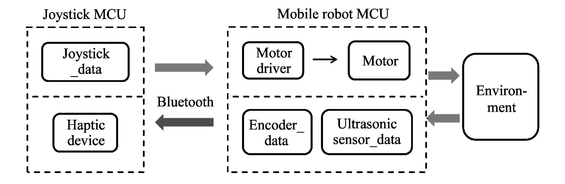
Fig.1 Schematic diagram of the whole system
1.2 Mobile robot configuration
Fig.2 shows the appearance of the mobile robot designed for this paper. And three ultrasonic sensors mounted on the front side can recognize the obstacle. The mobile robot is configured with two MCUs. MCU2 estimates the distance and angle of the mobile robot and the obstacles using ultrasonic sensors, and then transfers the measured data to MCU1. MCU1 controls the mobile robot by using joystick data. The velocity of the mobile robot is measured by the encoder mounted on the motor.
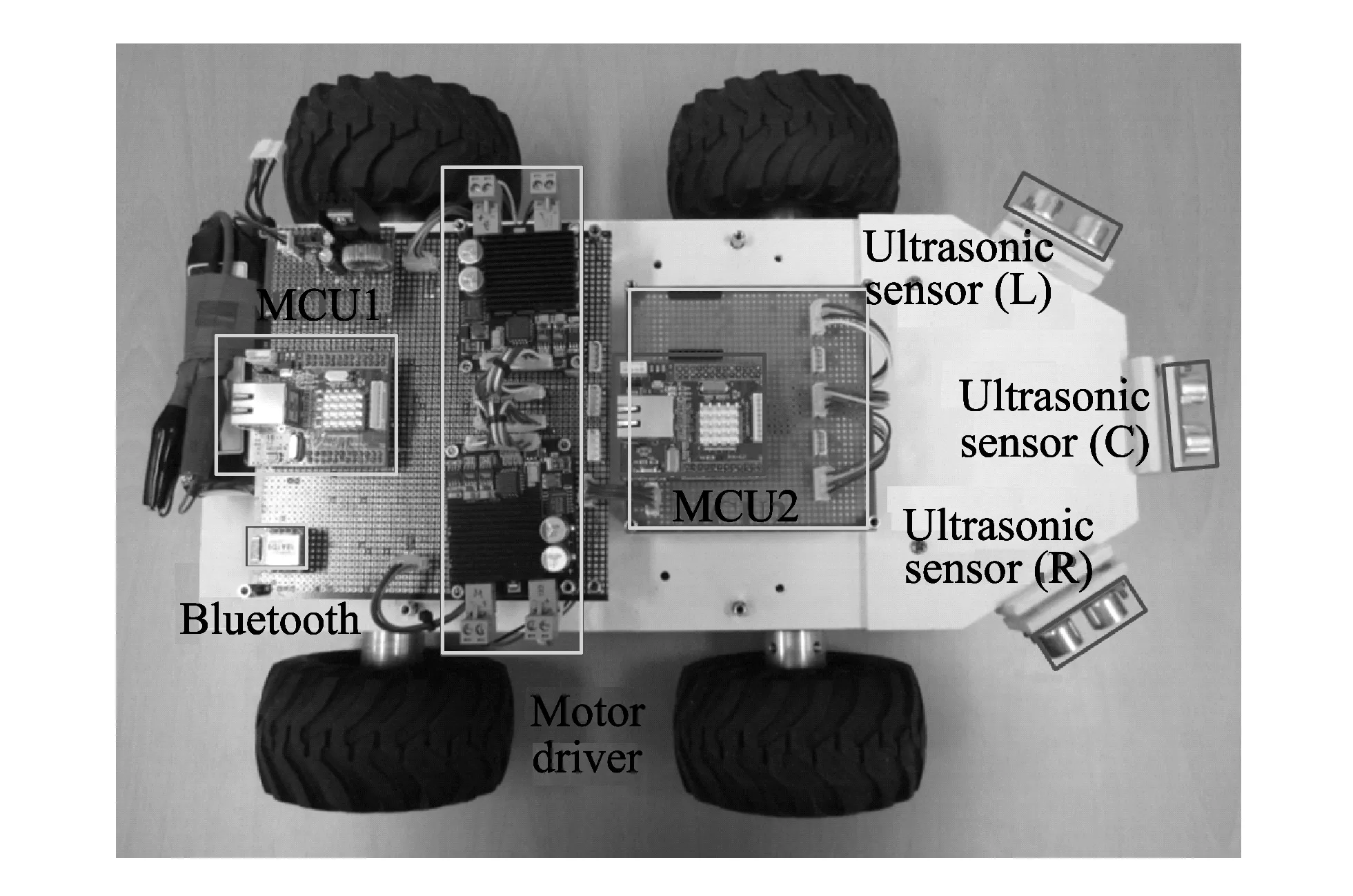
Fig.2 Composition of mobile robot
1.3 Superposition of ultrasonic sensors to estimate the position of obstacles
As shown in Fig.3, the ultrasonic sensor can measure the distance to the obstacles that are located within the beam width, for example, in the case of Figs.3 (a) and (b). However, it can not measure the exact location of the obstacles. This feature of the ultrasonic sensor is called the uncertainty of locations[7,8]. In order to reduce the uncertainty of locations, we nest three ultrasonic sensors to more precisely recognize the location of obstacles[9,10].

Fig.3 Position uncertainty of ultrasonic sensor
Fig.4 shows the ultrasonic sensors SL, SCand SR. They have corssed beams nested on the radius of circle that is not zero. SCcrosses the full detection area of the ultrasonic sensor, which is divided into three small areas (LC,C,RC) because of the nested beam width of ultrasonic sensors.

Fig.4 Position uncertainty reduction due to beam overlap
The combination of ultrasonic sensors for detecting obstacles depending on the relative position of the obstacle in the beam width of the ultrasonic sensor can be changed. As a result, it is possible to subdivide zones where obstacles are present through combination of ultrasonic sensors for detecting obstacles. Thus it becomes possible to reduce the uncertainty of the position of the unique ultrasonic sensor. The ultrasonic sensor which consists of its nested ring should be disposed in circumference where it is nonzero radius because of the size of its own as shown in Fig.5.
The ultrasonic sensor can provide the distance from a obstacle which is based on its vertex, but it has to be changed to the distance from obstacle which is based on the benchmark O of the nested ultrasonic sensor for the implementation of obstacle avoidance and obstacle detection.
The obstacle detection range of the nested ultrasonic sensor is determined by Eq.(1) considering the obstacle detection square area shown in Fig.5.
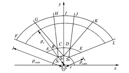
Fig.5 Three adjacent overlapped ultrasonic sensor
where ρo,minin Eq.(2) is the distance from the center of the nested ultrasonic sensor ring to the vertex of the obstacle detection square area. ρo,maxin Eq.(3) is the distance of the obstacle on the basis of the center of ultrasonic sensor ring corresponding to the maximum detection distance of the ultrasonic sensor. In this paper, the experiment is conducted by specifying the maximum detection distance of the ultrasonic sensor with in 1 m[11,12].
1.4 Haptic device configuration
Fig.6 shows the haptic device proposed in this paper. Haptic device composed of five vibration motors is produced. By mounting it on a joystick, haptic joystick is made. Haptic device is designed with consideration that haptic joystick can be combined with a kind of joystick is realized and vibration motors can be equipped through intuitive structure and position of the obstacle. By use of vibration generated by vibration motors, the position of the obstacle is recognized. Motors from 1 to 5 make the user have the sense of direction from left to right.

Fig.6 Haptic device
If vibration is generated by vibration motors on haptic device, the user knows that there is an obstacle in that direction. The user can control the mobile robot to avoid the obstacle with joystick by means of the information about the obstacle.
2 Design of haptic controller
The user can know the position of the obstacle estimated by the measured data of the ultrasonic sensor. Representation of haptic using haptic device needs algorithms that can estimate the position of obstacle and react intelligently in accordance with current states in similar direction of the mobile robot.
In this paper, we have controlled haptic device using fuzzy rule. The performance of fuzzy rule may vary depending on configuration method of fuzzy rule. For better performance, optimization process of fuzzy rule is required. The fuzzy rule is as follows.

The fuzzy rule used in this paper consists of two inputs and one output, as shown in Fig.7. Input variables of fuzzy algorithm use position information of the obstacles on the right side and the left side in front of the mobile robot to operate haptic device. Operation situation is known by using the obtained result value. To decide the result value, the Mamdani inference scheme, the center of gravity (COG) defuzzification method, is used and expressed with qualitative language.

Fig.7 Structure diagram of fuzzy rule
Table 1 shows the designed fuzzy rule. The output value is the number of motor in Fig.6. Fuzzy rule is considered for the location of obstacles. According to the location of the obstacle measured by ultrasonic sensor, the user can sense the location of the obstacle through vibration generated by the haptic devices. The user is aware of the location and existence of obstacles in a situation they cannot see. As a result, haptic interface is implemented to avoid obstacles[13,14].

Table 1 Input and output of fuzzy rule
3 Experiments and discussion
3.1 Experimental environment
This experiment is carried out in the second floor lobby, Samsung University-Industrial Alliance Building in Pusan University. The distance and location of obstacles are from the measured data using the nested ultrasonic sensors.
Fig.8 shows the experimental environment for performance analysis which is for user to recognize the exact obstacle by using a haptic device. Mobile robot recognizes the exact obstacle through the nested ultrasonic sensors.

Fig.8 Experimental environment
Through haptic device, performance analysis is done if it gives information exactly about obstacles to users. It assumes the three cases for performance analysis. Table 2 indicates the operation state of the vibration motor that is attached to a haptic device. Vibration motor is operated depending on the mode of the haptic device, and the number of the vibration motor is depicted in Fig.6.

Table 2 Representation of haptic device's operation state
3.2 Experimental results
Fig.9 is performance analysis of the haptic device from mobile robot's recognition of an obstacle in the environment of experiment 1.

Fig.9 Performance analysis depending on recognition of obstacle (Experiment 1)
In case the obstacle is present on the left side of the mobile robot, the performance of the haptic device is analyzed in accordance with situation that it approaches to the obstacle. In section ①, mobile robot recognizes the position of the obstacle through the nesting of the ultrasonic sensor, and haptic device is operating according to the situation. In section ②, the haptic device operates in accordance with the situation that mobile robot passes the obstacle closed to the left side of it.
If vibration is generated by vibration motors on haptic device, the user knows that there is an obstacle in that direction. The user can control the mobile robot to avoid the obstacle with joystick by means of the information about the obstacle.
Fig.10 is performance analysis of the haptic device according to mobile robot's recognition of obstacle in the environment of Experiment 2.
If an obstacle is present in two locations left and center of the mobile robot, the performance of the haptic device is described and analyzed in the same manner. In section ①, mobile robot firstly recognizes obstacles present on the left side and haptic device operates in accordance with that situation. In section ②, mobile robot accurately recognizes the position of the two obstacles and the haptic device operates to match the situation. In section ③, mobile robot only recognizes the obstacle in the middle when passing the obstacle on the left.

Fig.10 Performance analysis depending on recognition of obstacle (Experiment 2)
Fig.11 is performance analysis of the haptic device in accordance with that mobile robot recognizes the obstacle in an environment of experiment 3. In the same manner as described above the performance of the haptic device is analyzed depending on the case that an obstacle is present on the two left and right sides of the mobile robot. In section ①, mobile robot recognizes obstacles of both left and right, it is a situation that is close to the obstacle. In section ②, this is a situation in which the mobile robot passes between the obstacles both left and right.
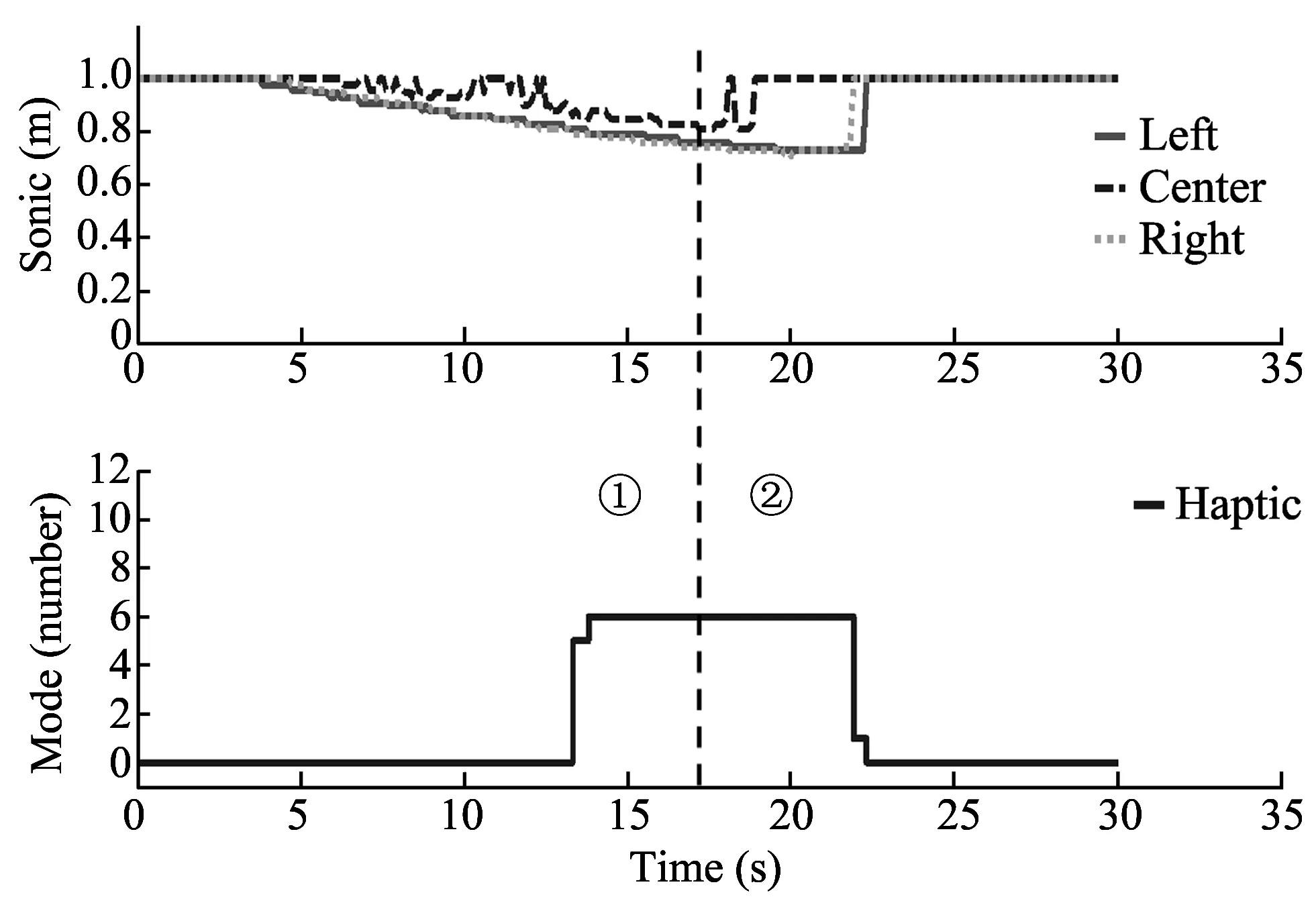
Fig.11 Performance analysis depending on recognition of obstacle (Experiment 3)
4 Conclusion
In this paper, a method is proposed that user recognizes the obstacle in the absence of display by using the proposed haptic device. Experiment results show that it is possible to accurately recognize the position information of the obstacle through haptic information generated by the haptic device. In future studies, an algorithm will be studied for traveling of the mobile robot based on the position information of the obstacle the user recognized.
[1] Kweon Y T, Kim M K, Kang H, et al. Remote control of a mobile robot using haptic device. In: Proceedings of Korean Society of Precision Engineering Autumn Conference, Busan, Korea, 2004: 120-124.
[2] Ko A K, Choi J Y, Kim H C, et al. A haptic interface using a force-feedback joystick. Journal of Institute of Control, Robotics and Systems, 2007, 13(12): 1207-1212.
[3] Yeo H J, Sung M H. Fuzzy control for the obstacle avoidance of remote control mobile robot. Journal of Institute of Electronics Engineers of Korea, 2011, 48(1): 47-54.
[4] Kyung K U, Park J S. The state of the art and R & D perceptives on haptics. Electronics and Telecommunications Trends, 2006, 21(5): 93-108.
[5] Kim H, Kyung K U, Park J, et al. The state-of-the-art on haptic interface. Information Technology, 2010, 8(1): 7-15.
[6] Han S, Lee J M. Tele-operation of a mobile robot using a force reflection joystick with a single hall sensor. In: Proceedings of the 16th IEEE International Conference on Robot & Human Interactive Communication, Jeju, Korea, 2007: 206-211.
[7] Choi Y K, Choi W S, Song J B. Obstacle avoidance of a mobile robot using low-cost ultrasonic sensors with wide beam angle. Journal of Institute of Control, Robotics and Systems, 2009, 15(11): 1102-1107.
[8] Kwon J H, Kim T Y, Lyou J. Corridor traveling and map building of an omni-directional mobile robot with ultrasonic array. In: Proceedings of the 7th Defense Technology Conference, Seoul, Korea, 2011: 820-829.
[9] Kim S B, Kim H B. Comparative analysis on performance indices of obstacle detection for an overlapped ultrasonic sensor ring. Journal of Institute of Control, Robotics and Systems, 2012, 18(4): 321-327.
[10] Kim S B, Kim H B. Design method of overlapped ultrasonic sensor ring for autonomous mobile robots. In: Proceedings of ICORS Annual Conference 2010, Chuncheon, Gangwon, Korea, 2010: 171-174.
[11] Kim S B, Lee S H. Positional uncertainty reduction of overlapped ultrasonic sensor ring for efficient mobile robot obstacle detection. Journal of Institute of Signal Processing and Systems, 2009, 10(3): 198-206.
[12] Kim S B, Kim H B. Optimally overlapped ultrasonic sensor ring with minimal positional uncertainly in obstacle detection. In: Proceedings of International Conference on Control Automation and Systems, Goyang, Gyeonggi, Korea, 2010: 546-550.
[13] Choi B J, Jin S. Design of simple-structured fuzzy logic system based driving controller for mobile robot. Journal of Korean Institute of Intelligent Systems, 2012, 22(1): 1-6.
[14] ZHU An-min, YANG S X. A fuzzy logic approach to reactive navigation of behavior-based mobile robots. In: Proceedings of IEEE International Conference on Robotics and Automation (ICRA'04) , New Orleans, LA, USA, 2004, 5: 5045-5050.
date: 2013-05-11
The MOTIE (Ministry of Trade, Industry and Energy), Korea, under the Human Resources Development Program for Special Environment Navigation/Localization National Robotics Research Center support program supervised by the NIPA (National IT Industry Promotion Agency) (H1502-13-1001); The MSIP(Ministry of Science, ICT & Future Planning), Korea, under the ITRC(Information Technology Research Center) support program (NIPA-2013-H0301-13-2006) supervised by the NIPA.
Jangmyung Lee (jmlee@pusan.ac.kr)
1674-8042(2013)04-0376-05
10.3969/j.issn.1674-8042.2013.04.016
杂志排行

Journal of Measurement Science and Instrumentation的其它文章
- A 4-layer method of developing integrated sensor systems with LabVIEW
- Calibration and compensation methods of installation error of electronic compass
- Design of shared bus DSP board in vector network analyzer
- Error modeling and analysis of inclinometer based on digital accelerometer
- Analysis of condition monitoring methods for electromotor on oil platform
- U disk recorder based on CH376 and ATmega 128