Study on GNSS satellite signal simulator
2013-12-20LIDongLIYonghong李永红YUEFengying岳凤英SUNLisen孙笠森ZHAOShengfei赵圣飞WANGEnhuai王恩怀
LI Dong (李 栋), LI Yong-hong (李永红), YUE Feng-ying (岳凤英), SUN Li-sen (孙笠森), ZHAO Sheng-fei (赵圣飞), WANG En-huai (王恩怀)
(School of Information and Communication Engineering, North University of China, Taiyuan 030051, China)
Study on GNSS satellite signal simulator
LI Dong (李 栋), LI Yong-hong (李永红), YUE Feng-ying (岳凤英), SUN Li-sen (孙笠森), ZHAO Sheng-fei (赵圣飞), WANG En-huai (王恩怀)
(School of Information and Communication Engineering, North University of China, Taiyuan 030051, China)
Satellite signal simulator for global navigation satellite system(GNSS) can evaluate the accuracy of capturing, tracing and positioning of GNSS receiver. It has significant use-value in the military and civil fields. The system adopts the overall design scheme of digital signal processor (DSP) and field-programmable gate array (FPGA). It consists of four modules: industrial control computer simulation software, mid-frequency signal generator, digital-to-analog (D/A) module and radio frequency (RF) module. In this paper, we test the dynamic performance of simulator using the dynamic scenes testing method, and the signal generated by the designed simulator is primarily validated.
global navigation satellite system(GNSS); digital signal processor (DSP); field-programmable gate array(FPGA); simulator
CLD number: TN967 Document code: A
There are four global positioning systems in the world at present, which are global positioning system (GPS) of America, global navigation satellite system (GLONASS) of Russia, Galileo navigation satellite system of European Union (EU) and compass navigation satellite system of China[1]. Among them, the latter two are under construction.
In recent years, with the quick development and wide application of the global navigation satellite system (GNSS) technology, people pay more and more attention to the development of satellite signal simulator. By means of the effects of factors such as dynamic characteristics of the carrier on the satellite signal, the satellite signal simulator can generate any satellite signal that receiver receives, thus providing a simulation environment for the development and test of navigation receivers[2]. The satellite signal simulator has a powerful function and extensive application. It can generate high dynamic navigation signal to test the acquisition system, to track performance of receivers and to verify the feasibility of testing scheme. It also can be the comparison standard for dynamic measurement precision of navigation receivers. So the satellite signal simulator has significant use-value in the military and civil fields[3,4].
1 Whole frame of GNSS satellite signal simulator
The major scheme of GNSS satellite signal simulator includes digital signal processor (DSP), field-programmable gate array (FPGA), industrial control computer(ICC).
DSP is responsible for most of calculating work in the generation process of analog signal, including calculation of trajectory, generation of navigation message, real-time calculation of satellite position, visible star judgement on simulation time and propagation delay calculation.
The general function of FPGA is to receive carrier control words, code control words and navigation message sent from DSP and to generate modulated signal.
ICC is mainly responsible for downloading scenes, ephemeris, almanac and other parameters. Meanwhile, ICC also controls liquid crystal display (LCD) display and keyboard response.
The block diagram of the whole hardware composition of the system is shown in Fig.1.
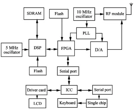
Fig.1 Structure diagram of hardware system
1.1 DSP communication design
During the working process of GNSS satellite signal simulator, DSP undertakes most of calculation work and communicates with serial port, external memory, FPGA and other parts at the same time.
1) Communication between DSP and external memory
Floating-point TMS320C6713BGDP of TI company is selected as DSP chip. Although DSP may produce mass of temporary data during the calculating process, for TMS320C6713B the maximum space available for program and data storage is 256 KB, which makes it enough for meeting the demands. And the design adopts synchronous dynamic random access memory with large capacity of external 128 MB to solve the problem. In addition, when the hardware circuit DSP runs offline, a piece of Flash of 4 MB is used for storage of code[5].
2) Communication between DSP and FPGA
There are many ways to realize the communication between DSP and FPGA, such as direct memory access, host port interface and so on. The design adopts an easy and reliable I/O pins directly connected communication method, which realizes the data exchange via external memory interface(EMIF) port. And it needs to set the configuration register in chip enable space of EMIF and adopts 32-bit asynchronous communication mode.
3) Communication between DSP and ICC
The communication between DSP and ICC realizes simulator system demand control, simulation parameters settings and return of real-time simulation data. Considering the flux of data between DSP and ICC is small and interaction frequency is not high, therefore this communication part can adopt RS232 serial interface communication method[6]. The RS232 interface of ICC is universal asynchronous receiver interface, but MCBPS of TI company's TMS320C6713B series DSP is synchronous serial interface. For this reason, there are two solutions: extending synchronous serial interface into asynchronous serial interface with serial port control chip or realizing the serial port control circuit with FPGA. To reduce the complexity of interface design, the paper adopts the latter. We set two first-in-first-outs (FIFOs) inside FPGA, one is called transmitting FIFO, which caches the data that DSP sends to ICC, and the other is receiving FIFO, which caches the data that ICC downloads to DSP.
1.2 Software design
In the calculation process of DSP, the initial control words of carrier numerical controlled oscillator(NCO) and code NCO are calculated according to the center frequency of the middle frequency signals of satellite. The control words are the accumulated values that DSP sends to FPGA, which are sent to NCO. Then whether the satellite is visible is judged one by one based on the relative position of satellite and receiver. For the visible satellite calculating the satellite signal's carrier phase and code phase that reaches to the front of receiver every ΔT and thus calculating the carrier phase difference Δτcand code phase difference Δτpevery other ΔT. By calculating the variable quantity of carrier control word and code control word related to their initial words, the real-time carrier control word and code control word are got. Considering the real-time ability of signal and processing capability of DSP, adopting the solution that sends new control word to FPGA every other 8 ms. During this period, DSP finishes the real-time calculation of pseudo range and transforms it into carrier phase and code phase[7]. And then they are transformed into carrier control word and code control word and transmitted to FPGA in the interrupt process program. The overall work flow of DSP is shown in Fig.2.
1.3 Interface design for DSP and FPGA
In the working process of simulator, there is a mess of data exchange between DSP and FPGA. By code control words accumulation, every 8 ms FPGA generates interrupt and sends it to DSP. When DSP receives the interrupt, it will send the real-time caching carrier control words and code control words to FPGA. Meanwhile, there will be interrupted counting in each channel of FPGA. If the accumulation of 1 ms reaches 20, in the next sending process of 1 ms interrupt, new navigation message will send the reguest for new navigation message to DSP. The signal exchange between DSP and FPGA in the working process is shown in Fig.3.
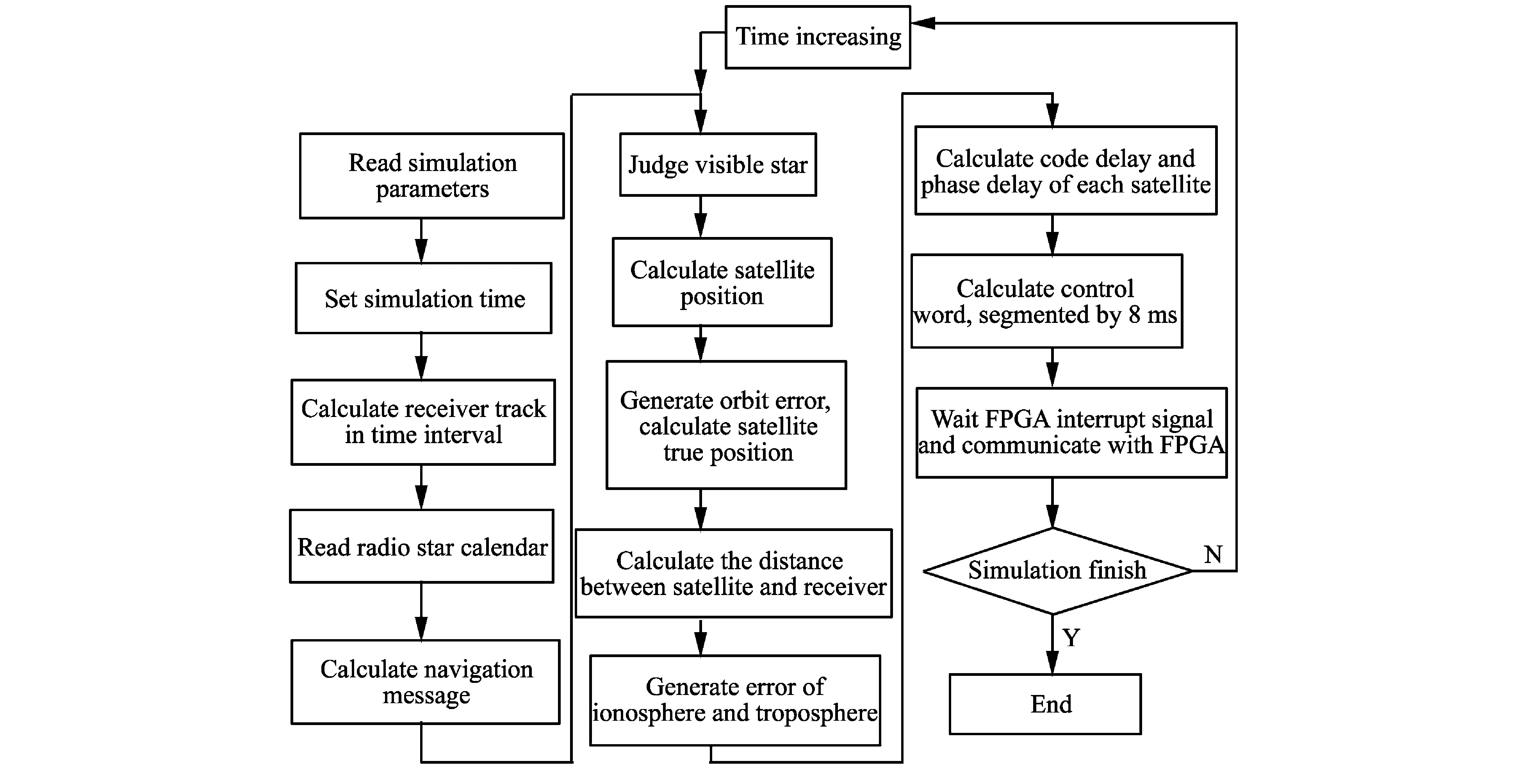
Fig.2 DSP block diagram of GNSS satellite simulator
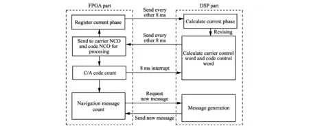
Fig.3 Single interactive diagram in the working process of DSP and FPGA
2 Test verification
The testing process of GNSS satellite signal simulator is as follows. Simulator outputs the simulation signal, and then receiver receives the simulation signal to realize positioning and records the positioning results, finally the data is processed using upper PC software. For dynamic scene, the testing data is large and the process is very complex. This design adopts the comparative analysis method to validate the performance of simulator. Spirent GSS 7700 overseas-based simulator is the representative product of navigational positioning system for testing the function of receiver. Using spirent simulator and the simulator developed by ourselves to test positioning information and analyze the results. The initial settings of scene are as follows: the latitude is 40°,the longitude is 116°, the altitude is 50 m, the initial velocity in east direction is 100 m/s, the velocities in the north and height directions are 0, and the acceleration in each direction is 0. The positioning results of the receiver in latitude, longitude and height are shown in Fig.4[8].
From the experimental results, it can be found that the dynamic signal has little measurement errors (latitude, longitude and height) between Spirent GSS 7700 simulator and the designed simulator. But in Fig.4(c), the error is big in height, it is mainly because the error model of the designed simulator is imperfect and it will be studied in the future[9,10].
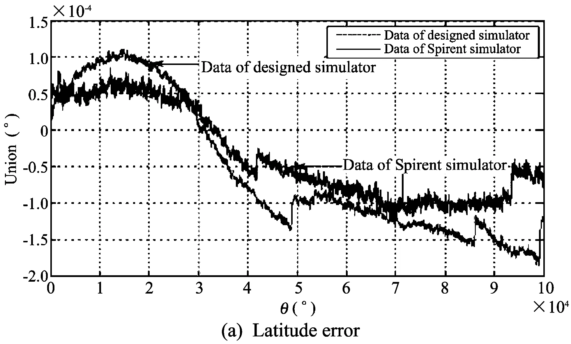
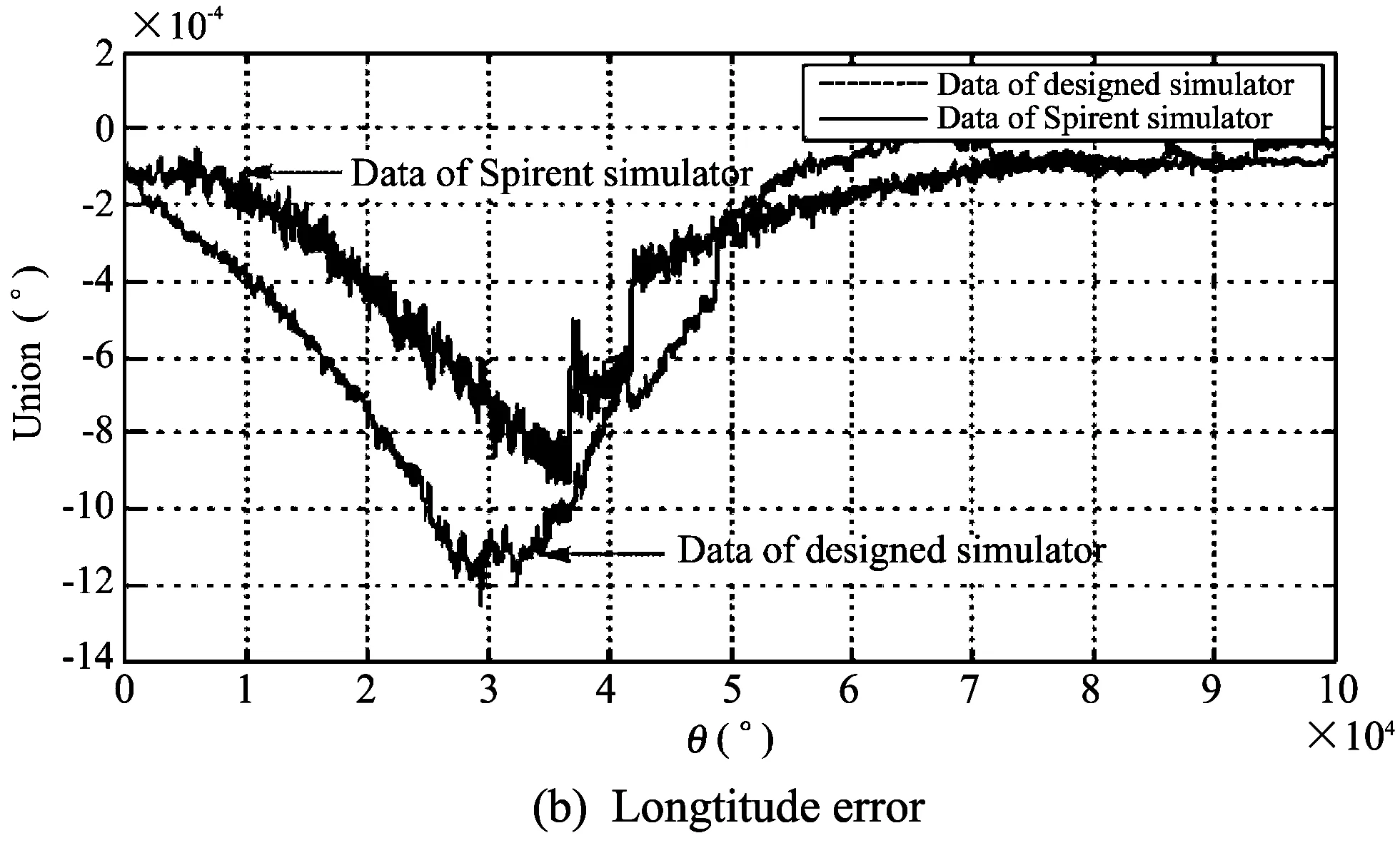

Fig.4 Positioning comparison of error of receiver
3 Conclusion
This paper designs a high dynamic GNSS satellite signal simulator. The system adopts the overall design scheme of DSP and FPGA, and the system con-sists of four modules: industrial computer simulation software, mid-frequency signal generator, D/A module
and RF module. The paper tests the dynamic performance of simulator using the dynamic scenes testing method, and the signal generated by the designed simulator is primarily validated.
[1] LI Jun. Analysis on the architecture of satellite navigation simulator. Radio Engineering, 2006, 36(8): 30-32.
[2] LEI Dong.IF GPS signal simulator development and verification. Calgary University, Alberta, Canada, 2003.
[3] LV Zhi-cheng, The software study on high dynamic satellite signal simulator. Changsha: National Defense University Press, 2006.
[4] Global positioning system wing (GPSW) systems engineering and integration interface specification IS-GPS-200E, Navstar GPS space segment / navigation user segment interfaces. Navstar GPS Joint Program Office, USA, 2010.
[5] WENG Hai-quan. Study on a method of decreasing the drift of MEMS gyroscope based on minimum resolution. Chinese Journal of Scientific Instrument, 2011,32(10): 2371-2375.
[6] Roncagliolo P A, de Blasis C E, Muravchik C H. GPS digital tracking loops designer for high dynamic launching vehicles. In: Proceedings of International Symposium on Spread Spectrum Techniques and Application, Tropical Manaus, 2006: 43-45.
[7] Roncagliolo P A, Garcia J G. High dynamic and false lock resistant GNSS carrier tracking loops. In: Proceedings of Insitute of Navigation GNSS, Fort Worth, Texas, USA, 2007: 2364-2375.
[8] TANG Kang-hua. Design of GPS receiver for embedded application field. Chinese Journal of Scientific Instrument, 2007, 28(8): 1497-1501.
[9] LUO Da-cheng. Design of a software GPS receiver. Chinese Journal of scientific Instrument, 2008, 29(9): 1856-1861.
[10] Gpoves P D. Principles of GNSS, inertial, and multi-sensor integrated navigation system. Artech House, London, 2008.
date: 2013-06-09
Shanxi Provincial Science and Technology Research Fund (No.2012021013-6)
LI Dong (469411125@qq.com)
1674-8042(2013)04-0349-04
10.3969/j.issn.1674-8042.2013.04.011
杂志排行
Journal of Measurement Science and Instrumentation的其它文章
- A 4-layer method of developing integrated sensor systems with LabVIEW
- Calibration and compensation methods of installation error of electronic compass
- Design of shared bus DSP board in vector network analyzer
- Error modeling and analysis of inclinometer based on digital accelerometer
- Analysis of condition monitoring methods for electromotor on oil platform
- U disk recorder based on CH376 and ATmega 128