Optical micro-scanning location calibration of thermal microscope imaging system
2013-11-05GUANCongrong关丛荣GAOMeijing高美静JINWeiqi金伟其WANGJihui王吉晖
GUAN Cong-rong(关丛荣), GAO Mei-jing(高美静), JIN Wei-qi(金伟其),WANG Ji-hui(王吉晖)
(1.MoE Key Laboratory of Photoelectronic Imaging Technology and System,School of Optoelectronics,Beijing Institute of Technology,Beijing 100081,China;2.College of Mechanical and Electrical Engineering,North China University of Technology,Beijing 100041,China;3.Department of Information Science and Engineering,Yanshan University,Qinhuangdao,Hebei 066004,China)
The subtle temperature distribution of the object detail can be obtained by thermal microscope imaging that is widely applied on the large scale integrated circuit chip design and detection,the thermal analysis of MEMS/MOEMS devices,biomedical engineering diagnosis and other fields extensively[1-2].The focal plane detector space discrete sampling and detector unit space integral,thermal microscope imaging generally belongs to undersampl imaging,even approaching the optical diffraction limited.With optical scanning technology,the spatial resolution of thermal microscope imaging system can be increased without increasing the detector dimension and reducing the detector unit size.Since optical micro-scanning can decrease sample space and increase space sampling rate,it can reduce the spectrum aliasing and improve the quality of thermal microscope imaging[3-4].
During the micro-scanning imaging process,multiple sampling is carried out on the same scene.And each displacement step of the focal plane array is the same,which is 1/N(N is an integer).Then the final micro-scanning image pixel number is N2times of the original image.For more scene information can be obtained with micro-scanning,the system spatial resolution can be improved greatly[5-6].
In Ref.[3],we used optical plate rotating micro-scanning technology and realized the thermal microscope system with optical micro-scanning device.However,as the relative location of the micro-scanning device and the detector would be changed after adjusting even each time,we should calibrate the relative location of the detector exactly.In Ref.[7],a calibration method of the initial location was put forward,and the other location was determined with rotating the microscanning device 90°each time.But from our experiments,we found the optical plate rotating trace was not a standard circle because of different errors accumulation.This makes the drawing of the actual four micro scanning location deviate from a square seriously.Above experiment phenomena indicated that the micro-scanning location had deviated from standard 90°interval.
In this paper,we studied each scanning location and proposed an adaptive method to calibrate micro-scanning location with the digital image displacement calculation and geometric method.
1 System composition
From Fig.1,optical plate rotating microscanning thermal microscope imaging system is made of infrared thermal imager,optical plate rotating micro scanning device,infrared microscope objective lens,mechanical structure component and computer[7].The object on the platform is imaged by the infrared focal plane array through the infrared objective lens and the micro scanning device.Then thermal microscope imaging is collected to computer by an image acquisition card.With 2×2 model four point mechanical microscanning scheme,the rotation of the micro-scanning device is placed in front of the focal plane array and controlled by the computer(Fig.2).
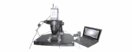
Fig.1 Optical plate rotating micro scanning thermal microscope
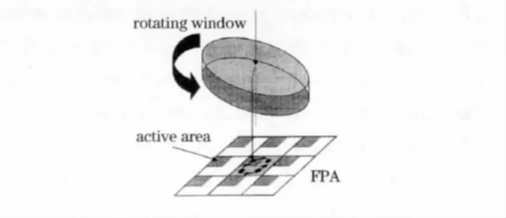
Fig.2 Sketch map of optical plate rotating
Optical plate has a leaning angle with the optical axis perpendicular direction.Mechanical device rotates it with 90°around the system optical axis.Then we can obtain four low resolution images of the same scene.Each image has the same displacement which is one-half of the detector photosensitive pixel size[8].
The 2×2 micro scanning location is shown in Fig.3.Dotted line circle is the trajectory of the optical plate.Right angle coordinate system xOy is established by the origin of the circle.A,B,C,D represent four standard location respectively,and they are located in the four quadrants of 45°,135°,225°,315°,formatting a standard 2 ×2 upright square that is shown as the continuous line in Fig.3.Though AB=L/2,(L is the detector photosensitive pixel size)
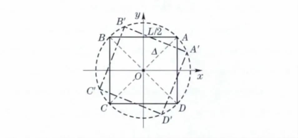
Fig.3 2 ×2 micro scanning location
The four images which are located on the standard location are undersampling and with low resolution.So we can use them to reconstruct high quality super resolution image.Furthermore the spatial resolution of the system is improved.This design has the advantages of simplicity,low cost,and the imaging uniformity does not change with the micro-scanning location.
However,after micro-scanning device is installed,its initial location may not coincide with arbitrary point of the standard upright square,and the rest of three points by rotating 90°are also wrong.So it is shown as the double-point-line square(A'B'C'D')rather than an upright square(Fig.3).As a result,if we use four images with their location not standardized,the quality of the reconstructed image will be reduced—even poorer than the image amplified by the original image with double linear interpolation method.Although the initial location is just one of the standard points such as A,the subsequent location will not be at the other standard points such as B,C,D.This is due to the vibration of the micro-scanning device rotation and influence of other environment effectors.So it is essential to calibrate the initial location and the following location of the micro-scanning device.
2 Micro scanning device location calibration
2.1 Initial location calibration
The initial location calibration of the microscanning device is to make the point of the device initial micro-scanning location coincide with any point of the 2×2 upright square.The calibration method is to utilize the displacement of two images at different locations to calculate the optical plate rotating angle which can coincide with the standard location.
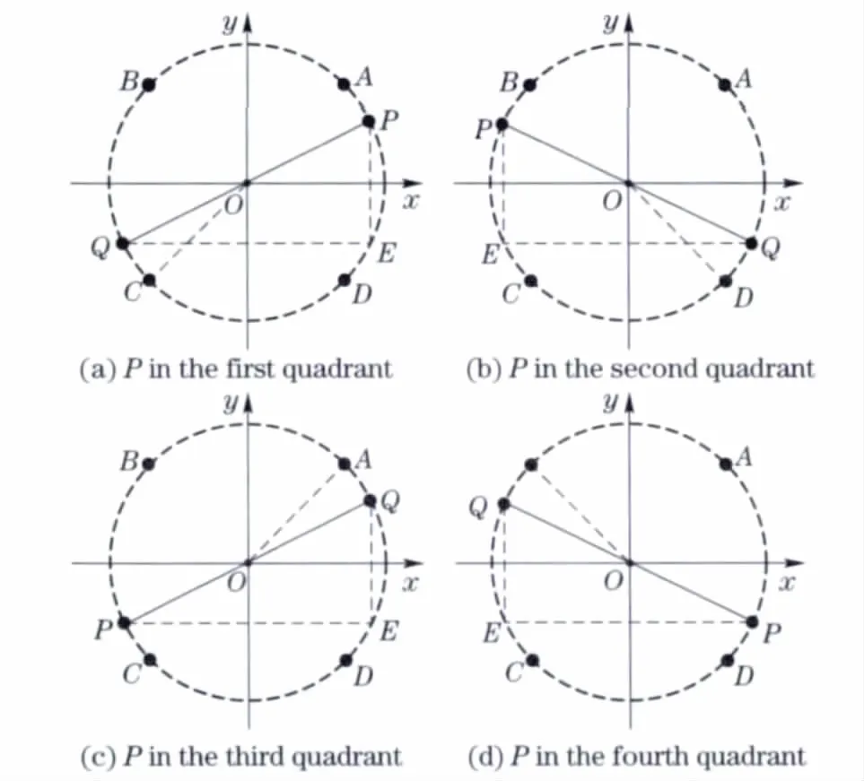
Fig.4 Micro-scanning initial location calibration
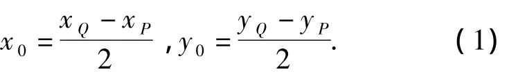
Micro-scanning initial location is shown in Fig.4.P(xP,yP)represents micro-scanning installation location,and Fig.4 shows its location in the four quadrants respectively.To find the rotating center,the optical plate is rotated 180°around the optical axis anticlockwise.Then P is rotated to Q(xQ,yQ)and the circle center coordinates of O(x0,y0)can be calculated as
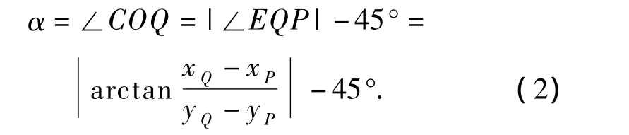
For the vibration of mechanical scanning in the rotating process,the location error will be increased with enlarging of the rotating angle.In order to reduce the effect of the mechanical vibration,the rotating angle should be as small as possible.So In Fig.4a we choose point C which is the closest point to Q as the initial location.We can see that the initial location calibration angle α equals∠QOC.Once∠QOC is calculated,the initial location calibration will be finished.
To calculate the size of∠QOC,a vertical line and a horizontal line through P and Q respectively are intersected as E,so α is
From Fig.4a,when α has the same sign as x0/y0,the optical plate should be rotated anticlockwise.
Similarly,as P is in other quadrant,we also can calculate the initial location calibration angle and determine the optical plate rotating direction as mentioned before.
2.2 Other location calibration
After the initial location calibration,the other location will be obtained by rotating the optical plate with step of 90°.Because of the uncertainty of outside environment conditions and the mechanical vibration of the micro-scanning device,the other location will be different.It may be point M near the standard location,as shown in Fig.5.
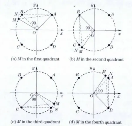
Fig.5 Other location calibration
If the optical plate is rotated continuously,the error of current location will be accumulated to the next location,which will decrease the quality of the reconstructed images with 2×2 micro scanning.To avoid the location error,it is necessary to calibrate each micro-scanning location with a method similar to the initial location calibration method.It also uses the displacement of two micro-scanning images to obtain calibration rotation angle and its rotating direction.
As shown in Fig.5a,the situation of point A is taken as the initial location for example.If the optical plate is rotated 90°anticlockwise,the micro-scanning location should be point B in theory.However,its actual position is landed on point M(xM,yM).So the location calibration angle βBis equal to∠BOM.To calculate∠BOM,a vertical line and a horizontal line through M and A respectively are intersected as point N,∠BOM and∠MAN are the central angle and round angle of the same arcMB,then βBis

when βB> 0,the optical plate should be rotated clockwise;when βB<0,it should be rotated anticlockwise.
Similarly,we can also calculate location calibration angle βiwhen the micro-scanning rotates at C,D and A:
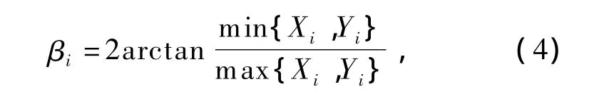
where βiis the other location calibration angle as the initial location has been calibrated,and i can be one of A,B,C and D.Yi,Xiare the ordinate and abscissa difference of the optical plate rotated after and before.
When βihas the same sign as|Yi| - |Xi|,the optical plate should be rotated anticlockwise;otherwise it should be rotated clockwise.
2.3 Adaptive location calibration
Although each location is calibrated,the error between calibrated location and the standard location is existent because of the uncertainty of outside environment conditions and system precision.So we established a new method called adaptive location calibration method (Fig.6)which uses a given offset to calibrate micro-scanning location repeatedly.First we got the image IPof the micro-scanning device assemble location.Then we rotated the optical plate 180°and got the image IQ.With the image registering and Eq.(2),the rotating angle α was calculated,and the rotating direction was determined.If α was bigger than the given offset,we rotated the optical plate and the image IQwas gotten to calculate α again.the initial location had been calibrated.And other location calibration is similarity to this repeatedly.
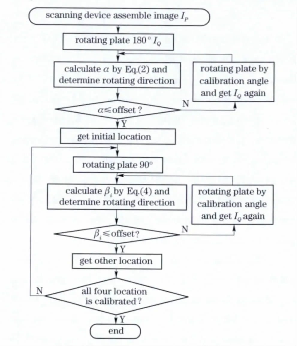
Fig.6 Adaptive location calibration flow chart
3 Location calibration and reconstructed experiment
With the micro-scanning location calibration method,the calibration experiments of optical plate rotating micro-scanning thermal microscopy imaging system were done as shown in Fig.7.
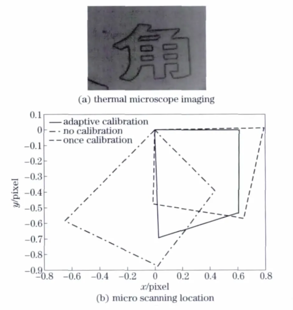
Fig.7 Location calibration experiment
Fig.7a shows a amplified part of a JIAO thermal microscopy imaging.Fig.7b is the scanning location before and afterthe calibration.In which,the coordinate unit is one pixel,the point line represents the scanning location without calibration,the dot dash line represents the scanning location with one time calibration,and the solid line represents the scanning location with adaptive calibration.These show that the location after adaptive calibration made the result most close to the standard upright square.
According to the three kinds of micro-displacement from Fig.7b,the four low resolution simulation Lena images had been created by original Lena(256×256)respectively.Then we directly embedded the four low resolution images to reconstruct the high resolution image.The adaptive location calibration results are shown in Fig.8,Fig.8a is the origin Lena image,and Fig.8b are the four low resolution simulated Lena(128×128)images.To appraise the reconstruct effects,the parameters of peak value signal-to-noise ratio(PSNR),general image quality factor(Q)and information entropy(SNT)[9-10]are shown in Tab.1.Q has the good measure ability at image degradation,the bigger the|Q|is,the higher the image quality is.SNT is the most important parameter to measure the image information without original image,and it is also hoped to be larger.
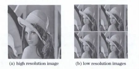
Fig.8 Simulation experiment results
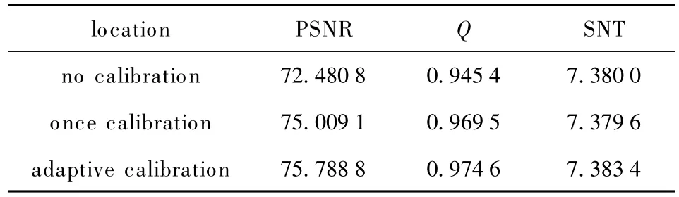
Tab.1 Lena reconstruction valuation parameters
From Tab.1,the reconstructed image with adaptive location calibration method has great reductive ability.And the gained image is clearer and has more distinguished details information.
The actual over sample reconstruction result is shown in Fig.9.And we can see that the reconstructed image after adaptive location calibration has better effect,and its SNT is larger.
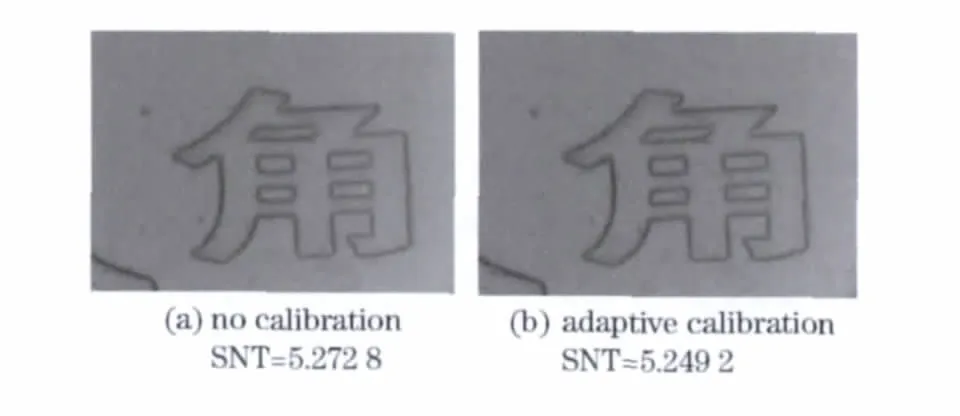
Fig.9 Result of thermal microscope imaging reconstruction
4 Conclusions
With optical plate rotating micro-scanning device,thermal microscope imaging system can get higher resolution under the condition of lower detector size.It is single construction,convenience control,fitting-in different imaging systems easily and could be applied in widespread scope.
Furthermore,the scanning location calibration is the crucial step to the device and needs special method.This paper had studied the optical plate rotating micro-scanning location calibration,and presented the adaptive location calibration method.Our experiments proved that the new method can improve the reconstructed image quality,and the space resolution is increased correspondingly.
[1] Wiltsc J M,Miller J L.Imagery improvements in staring infrared imagers by employing subpixel microscan[J].Optical Engineering,2005,44(5):056401- 056409.
[2] Lee S Y,Tung H W,Chen W C,et al.Thermal actuated solid tunable lens[J].IEEE Photonics Technology Letters,2006,18(21):2191- 2193.
[3] Gao Meijing,Jin Weiqi,Wang Xia,et al.Design and implementation of optical micro-scanning thermal microscope imaging system with high resolution[J]. Chinese Journal ofScientific Instrument,2009,30(5):1037-1041.(in Chinese)
[4] Joachimsthaler I,Zimmermann G,Heiderhoff R.SEM/STEM-hybrid-system:a new tool for advanced thermal analysis of electronic devices[C]∥Proceeding of 9th IPFA.Singapore:[s.n.],2002:196-200.
[5] Zhang Yi,Bai Lianfa,Chen Qian,et al.Performance analysis and computation for spatial resolving capability of IRFPA micro-scan[J].Infrared and Laser Engineering,2009,38(2):221-225.(in Chinese)
[6] Qu Huiming,Chen Qian.Comparison of microscanning schemes in infrared focal plane array imaging[J].Laser & Infrared,2006,36(3):161 -164.(in Chinese)
[7] Gao Meijing,Jin Weiqi,Wang Xia,et al.Zero calibration for the designed microscanning thermal microscope imaging system[J].Acta Opitca Sinica,2009,29(8):2175-2179.(in Chinese)
[8] Wang Lei,Shen Tingzhi.Two-dimensional entropy method based on genetic algorithm[J].Journal of Beijing Institute of Technology,2002,11(2):184-188.
[9] Xydeas C S,Petrovic V.Objective image fusion performance measure[J].Electronics Letters,2000,36(4):308-310.
[10] Petrovic V,Xydeas C S.Sensor noise effects on signal-level image fusion performance[J].Information Fusion,2003,4(3):167-183.
杂志排行

Journal of Beijing Institute of Technology的其它文章
- Temperature field simulation technology for thermostat electromechanical systems
- Weight distribution of sub-munitions fuze design
- Analysis of vehicle powertrain dynamic performance
- Roundness error evaluation by minimum zone circle via microscope inspection
- Strategy to control crawling vehicles with automated mechanical transmission
- Control strategy for hybrid tracked vehicles using fuzzy logic